示例:将第 2 层电路与第 2 层电路互连
此示例提供了用于配置和验证到第 2 层电路互连的第 2 层电路的分步过程和命令。其中包含以下部分:
要求
此示例使用以下硬件和软件组件:
Junos OS 9.3 或更高版本
2 台 MX 系列路由器
2 M 系列路由器
1 T 系列路由器
1 个 EX 系列路由器
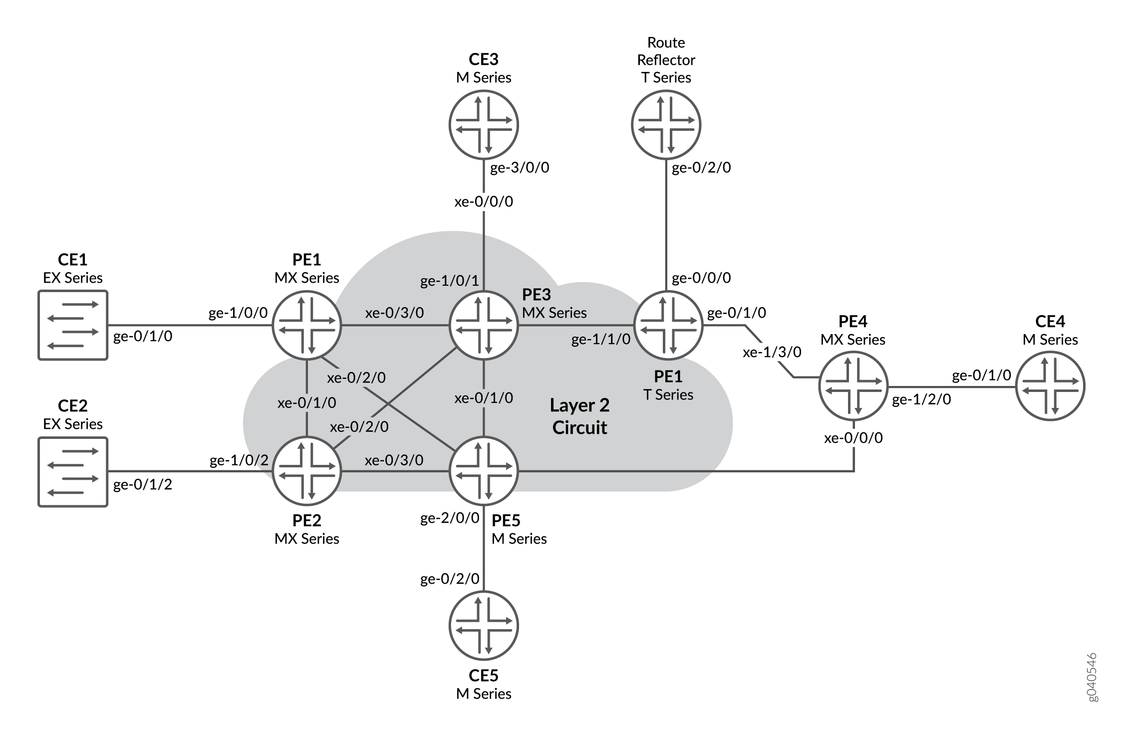
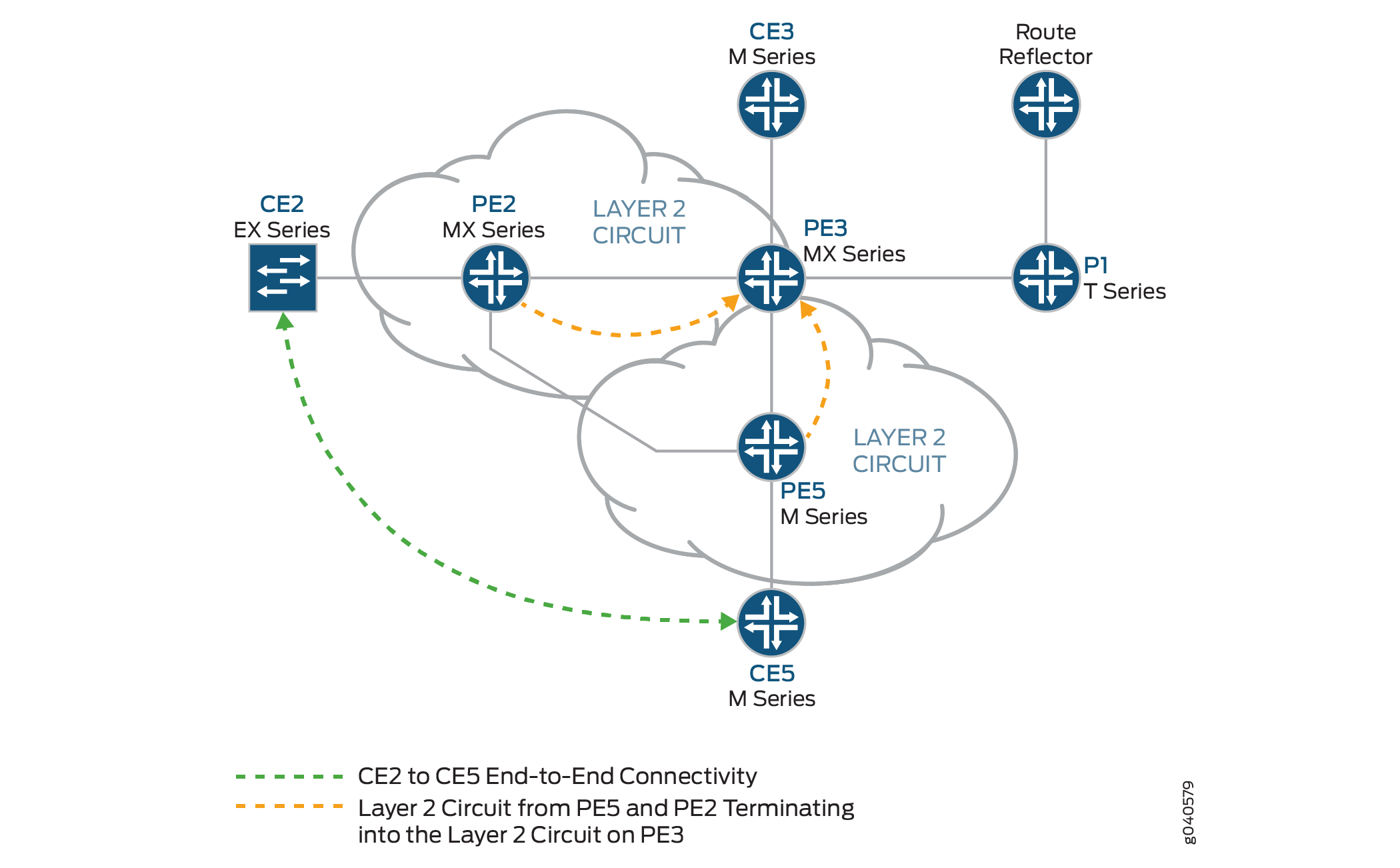
概述和拓扑
配置
在任何配置会话中,都最好定期验证可以使用命令提交 commit check 配置。
在此示例中,使用以下命令提示识别要配置的路由器:
CE2标识客户边缘 2 (CE2) 路由器PE1标识提供商边缘 1 (PE1) 路由器CE3标识客户边缘 3 (CE3) 路由器PE3标识提供商边缘 3 (PE3) 路由器CE5标识客户边缘 5 (CE5) 路由器PE5标识提供商边缘 5 (PE5) 路由器
此示例包含以下过程:
配置 PE 路由器面向客户的和环路接口
逐步过程
要开始构建互连,请在 PE 路由器上配置接口。如果您的网络包含提供商 (P) 路由器,请同时配置 P 路由器上的接口。此示例显示了路由器 PE1 和路由器 PE5 的配置。
在路由器 PE1 上
ge-1/0/0,配置接口封装。要配置接口封装,请包含语句encapsulation并指定ethernet-ccc选项(也支持 vlan-ccc 封装)。ge-1/0/0.0配置逻辑接口系列以实现电路交叉连接功能。要配置逻辑接口系列,请包括family语句并指定ccc选项。[edit interfaces] ge-1/0/0 { encapsulation ethernet-ccc; unit 0 { family ccc; } } lo0 { unit 0 { family inet { address 192.0.2.1/24; } } }在路由器 PE5 上
ge-2/0/0,配置接口封装。要配置接口封装,请包含语句encapsulation并指定ethernet-ccc选项。ge-2/0/0.0配置逻辑接口系列以实现电路交叉连接功能。要配置逻辑接口系列,请包括语句family并指定ccc选项[edit interfaces] ge-2/0/0 { encapsulation ethernet-ccc; unit 0 { family ccc; } } lo0 { unit 0 { family inet { address 192.0.2.5/24; } } }在路由器 PE3 上,配置逻辑环路接口。环路接口用于建立路由器 PE1 和 PE5 的目标 LDP 会话。
[edit interfaces]
lo0 {
    unit 0 {
        family inet {
            address 192.0.2.3/24;
        }
    }
}
配置面向核心的接口
逐步过程
此过程介绍如何在 PE 路由器上配置面向核心的接口。此示例不包括物理拓扑图中显示的所有面向核心的接口。在面向核心的 mpls 接口上启用和 inet 地址族。
在路由器 PE1 上
xe-0/3/0,配置接口。包括语句family并指定inet地址族。包括语句address并指定10.10.1.1/30为接口地址。包括语句family并指定mpls地址族。[edit interfaces] xe-0/3/0 { unit 0 { family inet { address 10.10.1.1/30; } family mpls; } }在路由器 PE3 上,配置面向核心的接口。包括语句
family并指定inet地址族。包括语句address并将示例中显示的 IPv4 地址指定为接口地址。包括语句family并指定mpls地址族。在示例中,xe-0/0/0接口连接到路由反射器,xe-0/1/0接口连接到路由器 PE5,xe-0/2/0接口连接到路由器 PE2,接口xe-0/3/0连接到路由器 PE1。[edit interfaces] xe-0/0/0 { unit 0 { family inet { address 10.10.20.2/30; } family mpls; } } xe-0/1/0 { unit 0 { family inet { address 10.10.6.1/30; } family mpls; } } xe-0/2/0 { unit 0 { family inet { address 10.10.5.2/30; } family mpls; } } xe-0/3/0 { unit 0 { family inet { address 10.10.1.2/30; } family mpls; } }在路由器 PE5 上
xe-0/1/0,配置接口。包括语句family并指定inet地址族。包括语句address并指定10.10.6.2/30为接口地址。包括语句family并指定mpls地址族。[edit interfaces] xe-0/1/0 { unit 0 { family inet { address 10.10.6.2/30; } family mpls; } }
配置协议
逐步过程
此过程介绍如何配置此示例中使用的协议。如果您的网络包含 P 路由器,请同时配置 P 路由器上的协议。
使用 OSPF 作为 IGP 协议来配置所有 PE 路由器和 P 路由器。在除之外 fxp.0的所有接口上启用 MPLS 和 LDP 协议。
在路由器 PE1 上,启用 OSPF 作为 IGP。在除之外
fxp.0的所有接口上启用 MPLS 和 LDP 协议。LDP 用作第 2 层电路的路由器 PE1 上的信令协议。以下配置片段显示了路由器 PE1 的协议配置:[edit] protocols { mpls { interface all; interface fxp0.0 { disable; } } ospf { traffic-engineering; area 0.0.0.0 { interface all; interface fxp0.0 { disable; } } } ldp { interface all; interface fxp0.0 { disable; } } }将 PE 和 P 路由器配置为 OSPF 作为 IGP。在除之外
fxp.0的所有接口上启用 MPLS 和 LDP 协议。以下配置片段显示了路由器 PE3 的协议配置:[edit] protocols { mpls { interface all; interface fxp0.0 { disable; } } ospf { traffic-engineering; area 0.0.0.0 { interface all; interface fxp0.0 { disable; } } } ldp { interface all; interface fxp0.0 { disable; } } }
配置第 2 层电路
逐步过程
此过程介绍如何配置第 2 层电路。
在此示例中, ignore-mtu-mismatch 电路需要语句。
在路由器 PE1 上,配置第 2 层电路。包括语句
l2circuit。包括该neighbor语句并将路由器 PE3 的环路 IPv4 地址指定为邻接方。包括接口语句并指定ge-1/0/0.0为参与第 2 层电路的逻辑接口。包括语句virtual-circuit-id并指定100为标识符。包括该ignore-mtu-mismatch语句以允许建立第 2 层电路,即使本地 PE 路由器上配置的最大传输单元 (MTU) 与远程 PE 路由器上配置的 MTU 不匹配。[edit] protocols { l2circuit { neighbor 192.0.2.3 { interface ge-1/0/0.0 { virtual-circuit-id 100; ignore-mtu-mismatch; } } } }在路由器 PE5 上,配置第 2 层电路。包括语句
l2circuit。包括该neighbor语句并将路由器 PE3 的环路 IPv4 地址指定为邻接方。包括接口语句并指定ge-2/0/0.0为参与第 2 层电路的逻辑接口。包括语句virtual-circuit-id并指定200为标识符。包括该ignore-mtu-mismatch语句以允许建立第 2 层电路,即使在本地 PE 路由器上配置的 MTU 与远程 PE 路由器上配置的 MTU 不匹配。[edit] protocols { l2circuit { neighbor 192.0.2.3 { interface ge-2/0/0.0 { virtual-circuit-id 200; ignore-mtu-mismatch; } } } }在路由器 PE3 上,将第 2 层电路配置为路由器 PE1。包括语句
l2circuit。包括该neighbor语句,并将路由器 PE1 的环路 IPv4 地址指定为邻接方。包括接口语句并指定iw0.0为参与第 2 层电路的逻辑互连接口。包括语句virtual-circuit-id并指定100为标识符。包括该ignore-mtu-mismatch语句以允许建立第 2 层电路,即使在本地 PE 路由器上配置的 MTU 与远程 PE 路由器上配置的 MTU 不匹配。在路由器 PE3 上,配置到路由器 PE5 的第 2 层电路。包括语句
l2circuit。包括该neighbor语句并将路由器 PE5 的环路 IPv4 地址指定为邻接方。包括接口语句并指定iw0.1为参与第 2 层电路的逻辑互连接口。包括语句virtual-circuit-id并指定200为标识符。包括语句ignore-mtu-mismatch。[edit protocols] l2circuit { neighbor 192.0.2.1 { interface iw0.0 { virtual-circuit-id 100; ignore-mtu-mismatch; } } neighbor 192.0.2.5 { interface iw0.1 { virtual-circuit-id 200; ignore-mtu-mismatch; } } }
第 2 层电路互连
逐步过程
路由器 PE3 是使用互连接口将第 2 层电路 拼接 在一起的路由器。对等单元接口的配置是互连的组成。
在路由器 PE3 上
iw0.0,配置接口。包括语句encapsulation并指定ethernet-ccc选项。包括语句peer-unit并将逻辑接口单元1指定为对等隧道接口。在路由器 PE3 上
iw0.1,配置接口。包括语句encapsulation并指定ethernet-ccc选项。包括语句peer-unit并将逻辑接口单元0指定为对等隧道接口。[edit interfaces] iw0 { unit 0 { encapsulation ethernet-ccc; peer-unit 1; } unit 1 { encapsulation ethernet-ccc; peer-unit 0; } }在路由器 PE3 上,配置第 2 层互连
l2iw协议。要配置第 2 层互连协议,请在l2iw层次结构级别包含语句[edit protocols]。[edit] protocols { l2iw; }在每台路由器上,提交配置。
user@host> commit check
configuration check succeeds
user@host> commit
验证第 2 层电路到第 2 层电路互连
逐步过程
验证路由器 PE1 上的第 2 层电路连接是否开启、LDP 邻接方是否正确以及 MPLS 标签操作是否正确。
在路由器 PE1 上,使用
show l2circuit connections命令验证从路由器 PE1 到路由器 PE3 的第 2 层电路是否为Up。user@PE1> show l2circuit connections Layer-2 Circuit Connections: Legend for connection status (St) EI -- encapsulation invalid NP -- interface h/w not present MM -- mtu mismatch Dn -- down EM -- encapsulation mismatch VC-Dn -- Virtual circuit Down CM -- control-word mismatch Up -- operational VM -- vlan id mismatch CF -- Call admission control failure OL -- no outgoing label IB -- TDM incompatible bitrate NC -- intf encaps not CCC/TCC TM -- TDM misconfiguration BK -- Backup Connection ST -- Standby Connection CB -- rcvd cell-bundle size bad XX -- unknown SP -- Static Pseudowire Legend for interface status Up -- operational Dn -- down Neighbor: 192.0.2.3 Interface Type St Time last up # Up trans ge-1/0/0.0(vc 100) rmtUpJan 5 22:00:49 2010 1 Remote PE: 192.0.2.3, Negotiated control-word: Yes (Null) Incoming label: 301328, Outgoing label: 314736 Local interface: ge-1/0/0.0, Status: Up, Encapsulation: ETHERNET在路由器 PE1 上,使用
show ldp neighbor命令验证路由器 PE3 的 IPv4 地址是否显示为 LDP 邻接方。user@PE1> show ldp neighbor Address Interface Label space ID Hold time 192.0.2.3 lo0.0 192.0.2.3:0 41
在路由器 PE 1 上,使用
show route table mpls.0命令验证第 2 层电路是否在两个方向(推送和弹出)上使用 LDP 标签到路由器 PE3。在以下示例中,第 2 层电路与 LDP 标签301328相关联。user@PE1> show route table mpls.0 mpls.0: 13 destinations, 13 routes (13 active, 0 holddown, 0 hidden) + = Active Route, - = Last Active, * = Both 0 *[MPLS/0] 1w1d 08:25:39, metric 1 Receive 1 *[MPLS/0] 1w1d 08:25:39, metric 1 Receive 2 *[MPLS/0] 1w1d 08:25:39, metric 1 Receive 300432 *[LDP/9] 3d 01:13:57, metric 1 > to 10.10.2.2 via xe-0/1/0.0, Pop 300432(S=0) *[LDP/9] 3d 01:13:57, metric 1 > to 10.10.2.2 via xe-0/1/0.0, Pop 300768 *[LDP/9] 3d 01:13:57, metric 1 > to 10.10.3.2 via xe-0/2/0.0, Pop 300768(S=0) *[LDP/9] 3d 01:13:57, metric 1 > to 10.10.3.2 via xe-0/2/0.0, Pop 300912 *[LDP/9] 3d 01:13:57, metric 1 > to 10.10.3.2 via xe-0/2/0.0, Swap 299856 301264 *[LDP/9] 3d 01:13:53, metric 1 > to 10.10.1.2 via xe-0/3/0.0, Swap 308224 301312 *[LDP/9] 3d 01:13:56, metric 1 > to 10.10.1.2 via xe-0/3/0.0, Pop 301312(S=0) *[LDP/9] 3d 01:13:56, metric 1 > to 10.10.1.2 via xe-0/3/0.0, Pop301328 *[L2CKT/7] 02:33:26 > via ge-1/0/0.0, Pop Offset: 4 ge-1/0/0.0 *[L2CKT/7] 02:33:26, metric2 1 > to 10.10.1.2 via xe-0/3/0.0, Push 314736 Offset: -4在路由器 PE3 上,使用
show l2circuit connections命令验证从路由器 PE3 到路由器 PE5 的第 2 层电路是否为Up、从路由器 PE3 到路由器 PE1 的第 2 层电路是否为Up,与路由器 PE1 和路由器 PE5 的连接使用 iw0 接口,以及本地 iw0 接口的状态是否为Up。user@PE3> show l2circuit connections Layer-2 Circuit Connections: Legend for connection status (St) EI -- encapsulation invalid NP -- interface h/w not present MM -- mtu mismatch Dn -- down EM -- encapsulation mismatch VC-Dn -- Virtual circuit Down CM -- control-word mismatch Up -- operational VM -- vlan id mismatch CF -- Call admission control failure OL -- no outgoing label IB -- TDM incompatible bitrate NC -- intf encaps not CCC/TCC TM -- TDM misconfiguration BK -- Backup Connection ST -- Standby Connection CB -- rcvd cell-bundle size bad XX -- unknown SP -- Static Pseudowire Legend for interface status Up -- operational Dn -- down Neighbor: 192.0.2.1 Interface Type St Time last up # Up trans iw0.0(vc 100) rmt Up Jan 5 13:50:14 2010 1 Remote PE: 192.0.2.1, Negotiated control-word: Yes (Null) Incoming label: 314736, Outgoing label: 301328 Local interface: iw0.0, Status: Up, Encapsulation: ETHERNET Neighbor: 192.0.2.5 Interface Type St Time last up # Up trans iw0.1(vc 200) rmt Up Jan 5 13:49:58 2010 1 Remote PE: 192.0.2.5, Negotiated control-word: Yes (Null) Incoming label: 314752, Outgoing label: 300208 Local interface: iw0.1, Status: Up, Encapsulation: ETHERNET在路由器 PE3 上,使用
show ldp neighbor命令验证是否将正确的 IPv4 地址显示为 LDP 邻接方。user@PE3> show ldp neighbor Address Interface Label space ID Hold time 192.0.2.1 lo0.0 192.0.2.1:0 44 192.0.2.2 lo0.0 192.0.2.2:0 42 192.0.2.4 lo0.0 192.0.2.4:0 31 192.0.2.5 lo0.0 192.0.2.5:0 44
在路由器 PE3 上,使用
show route table mpls.0命令验证路由表是否mpls.0填充了第 2 层互连路由。请注意,在此示例中,路由器将交换从路由器 PE1 收到的标签314736到标签301328。iw0.0user@PE3> show route table mpls.0 mpls.0: 16 destinations, 18 routes (16 active, 2 holddown, 0 hidden) + = Active Route, - = Last Active, * = Both 0 *[MPLS/0] 1w1d 08:28:24, metric 1 Receive 1 *[MPLS/0] 1w1d 08:28:24, metric 1 Receive 2 *[MPLS/0] 1w1d 08:28:24, metric 1 Receive 308160 *[LDP/9] 3d 01:16:55, metric 1 > to 10.10.1.1 via xe-0/3/0.0, Pop 308160(S=0) *[LDP/9] 3d 01:16:55, metric 1 > to 10.10.1.1 via xe-0/3/0.0, Pop 308176 *[LDP/9] 3d 01:16:54, metric 1 > to 10.10.6.2 via xe-0/1/0.0, Pop 308176(S=0) *[LDP/9] 3d 01:16:54, metric 1 > to 10.10.6.2 via xe-0/1/0.0, Pop 308192 *[LDP/9] 00:21:40, metric 1 > to 10.10.20.1 via xe-0/0/0.0, Swap 601649 to 10.10.6.2 via xe-0/1/0.0, Swap 299856 308208 *[LDP/9] 3d 01:16:54, metric 1 > to 10.10.5.1 via xe-0/2/0.0, Pop 308208(S=0) *[LDP/9] 3d 01:16:54, metric 1 > to 10.10.5.1 via xe-0/2/0.0, Pop 308224 *[LDP/9] 3d 01:16:52, metric 1 > to 10.10.20.1 via xe-0/0/0.0, Pop 308224(S=0) *[LDP/9] 3d 01:16:52, metric 1 > to 10.10.20.1 via xe-0/0/0.0, Pop 314736 *[L2IW/6] 02:35:31, metric2 1 > to 10.10.6.2 via xe-0/1/0.0, Swap 300208 [L2CKT/7] 02:35:31 > via iw0.0, Pop Offset: 4 314752 *[L2IW/6] 02:35:31, metric2 1 > to 10.10.1.1 via xe-0/3/0.0, Swap 301328 [L2CKT/7] 02:35:47 > via iw0.1, Pop Offset: 4 iw0.0 *[L2CKT/7] 02:35:31, metric2 1 > to 10.10.1.1 via xe-0/3/0.0, Push 301328 Offset: -4 iw0.1 *[L2CKT/7] 02:35:47, metric2 1 > to 10.10.6.2 via xe-0/1/0.0, Push 300208 Offset: -4使用命令,验证路由器 CE1 是否可以通过互连向路由器 CE5 发送流量以及接收来自路由器 CE5 的
ping流量。user@CE1>
ping 198.51.100.11PING 198.51.100.11 (198.51.100.11): 56 data bytes 64 bytes from 198.51.100.11: icmp_seq=1 ttl=64 time=22.425 ms 64 bytes from 198.51.100.11: icmp_seq=2 ttl=64 time=1.299 ms 64 bytes from 198.51.100.11: icmp_seq=3 ttl=64 time=1.032 ms 64 bytes from 198.51.100.11: icmp_seq=4 ttl=64 time=1.029 ms使用命令验证路由器 CE5 是否可以通过互连向路由器 CE1 发送流量以及接收来自路由器 CE1 的
ping流量。user@CE5>
ping 198.51.100.1PING 198.51.100.1 (198.51.100.1): 56 data bytes 64 bytes from 198.51.100.1: icmp_seq=0 ttl=64 time=1.077 ms 64 bytes from 198.51.100.1: icmp_seq=1 ttl=64 time=0.957 ms 64 bytes from 198.51.100.1: icmp_seq=2 ttl=64 time=1.057 ms 1.017 ms
结果
此示例的配置和验证已完成。以下部分可供参考。
路由器 PE1 的相关配置示例如下。
路由器 PE1
[edit]
interfaces {
    xe-0/1/0 {
        unit 0 {
            family inet {
                address 10.10.2.1/30;
            }
            family mpls;
        }
    }
    xe-0/2/0 {
        unit 0 {
            family inet {
                address 10.10.3..1/30;
            }
            family mpls;
        }
    }
    xe-0/3/0 {
        unit 0 {
            family inet {
                address 10.10.1.1/30;
            }
            family mpls;
        }
    }
    ge-1/0/0 {
        encapsulation ethernet-ccc;
        unit 0 {
            family ccc;
        }
    }
    lo0 {
        unit 0 {
            family inet {
                address 192.0.2.1/24;
            }
        }
    }
}
forwarding-options {
    hash-key {
        family inet {
            layer-3;
            layer-4;
        }
        family mpls {
            label-1;
            label-2;
        }
    }
}
routing-options {
    static {
        route 172.16.0.0/8 next-hop 172.19.59.1;
    }
    autonomous-system 65000;
}
protocols {
    mpls {
        interface all;
        interface fxp0.0 {
            disable;
        }
    }
    ospf {
        traffic-engineering;
        area 0.0.0.0 {
            interface all;
            interface fxp0.0 {
                disable;
            }
        }
    }
    ldp {
        interface all;
        interface fxp0.0 {
            disable;
        }
    }
    l2circuit {
        neighbor 192.0.2.3 {
            interface ge-1/0/0.0 {
                virtual-circuit-id 100;
                ignore-mtu-mismatch;
            }
        }
    }
}
路由器 PE3 的相关配置示例如下。
路由器 PE3
[edit]
interfaces {
    xe-0/0/0 {
        unit 0 {
            family inet {
                address 10.10.20.2/30;
            }
            family mpls;
        }
    }
    xe-0/1/0 {
        unit 0 {
            family inet {
                address 10.10.6.1/30;
            }
            family mpls;
        }
    }
    xe-0/2/0 {
        unit 0 {
            family inet {
                address 10.10.5.2/30;
            }
            family mpls;
        }
    }
    xe-0/3/0 {
        unit 0 {
            family inet {
                address 10.10.1.2/30;
            }
            family mpls;
        }
    }
    ge-1/0/1 {
        encapsulation ethernet-ccc;
        unit 0 {
            family ccc;
        }
    }
    iw0 {
        unit 0 {
            encapsulation ethernet-ccc;
            peer-unit 1;
        }
        unit 1 {
            encapsulation ethernet-ccc;
            peer-unit 0;
        }
    }
    lo0 {
        unit 0 {
            family inet {
                address 192.0.2.3/24;
            }
        }
    }
}
routing-options {
    static {
        route 172.16.0.0/8 next-hop 172.19.59.1;
    }
    autonomous-system 65000;
}
protocols {
    l2iw;
    mpls {
        interface all;
        interface fxp0.0 {
            disable;
        }
    }
    ospf {
        area 0.0.0.0 {
            interface all;
            interface fxp0.0 {
                disable;
            }
        }
    }
    ldp {
        interface all;
        interface fxp0.0 {
            disable;
        }
    }
    l2circuit {
        neighbor 192.0.2.1 {
            interface iw0.0 {
                virtual-circuit-id 100;
                ignore-mtu-mismatch;
            }
        }
        neighbor 192.0.2.5 {
            interface iw0.1 {
                virtual-circuit-id 200;
                ignore-mtu-mismatch;
            }
        }
    }
}


