本页内容
示例:为第 2 层电路配置出口保护 LSP
此示例说明如何配置出口保护 LSP。
要求
出口保护 LSP 仅在瞻博网络 MX 系列路由器上受支持。此要求适用于促进出口保护 LSP 的 PE 路由器。
出口保护 LSP 概述
如果核心网络中存在链路或节点故障,可以在 PE 路由器之间的传输 LSP 上触发 MPLS 快速重新路由等保护机制,从而在几十毫秒内修复连接。出口保护 LSP 解决了网络边缘发生链路故障时的问题(例如,PE 路由器和 CE 设备之间的链路故障)。出口保护 LSP 无法解决网络边缘的节点故障问题(例如,PE 路由器故障)。出口保护 LSP 是 RSVP 信号的终极跃点弹出 LSP。
此示例包含以下配置概念和语句,这些配置概念和语句是出口保护 LSP 配置所特有的:
context-identifier- 指定一个 IPV4 地址,用于定义参与出口保护 LSP 的 PE 路由器对。上下文标识符用于为保护或 PE 路由器分配标识符。该标识符传播到参与网络的其他 PE 路由器,从而使受保护的出口 PE 路由器能够向保护器 PE 路由器发出出口保护 LSP 信号。egress-protection—为受保护的第 2 层电路配置保护器信息,并在层次结构级别配置保护器第 2 层电路[edit protocols l2circuit]。将 LSP 配置为层级的[edit protocols mpls label-switched-path lsp-name]出口保护 LSP。它还在层次结构级别配置上下文标识符[edit protocols mpls]。protected-l2circuit- 指定哪个第 2 层电路受出口保护 LSP 保护。此语句包含以下子语句:ingress-pe、egress-pe和virtual-circuit-id。这些子语句分别指定 PE 路由器在第 2 层电路入口处的地址、第 2 层电路出口处的 PE 路由器地址,以及第 2 层电路的标识符。protector-interface- 指定出口保护 LSP 使用的接口。如果 CE 设备的本地链路故障,则出口保护 LSP 使用指定的接口与保护器 PE 路由器通信。protector-pe- 指定保护或 PE 路由器的 IPv4 地址。保护器 PE 路由器必须与受保护的 PE 路由器连接到同一 CE 设备,才能使出口保护 LSP 正常工作。此语句包含以下子语句:context-identifier和lsp。该lsp语句指定要用作实际出口保护 LSP 的 LSP。
拓扑
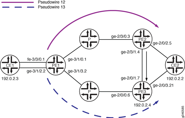 配置的出口保护 LSP
伪线配置沿两条路径进行配置:一条从路由器 PE1 到路由器 PE2(伪线 12),一条从路由器 PE1 到路由器 PE3(伪线 13)。如果路由器 PE2 和设备 CE2 之间的链路出现故障,流量将切换到路由器 PE2 和路由器 PE3(保护器 PE 路由器)之间配置的出口保护 LSP:
设备 CE1 — 流量来源
路由器 PE1 — 入口 PE 路由器
路由器 PE2 — 出口 PE 路由器
路由器 PE3 — 保护或 PE 路由器
设备 CE2 — 流量目的地
此示例说明如何配置路由器 PE1、PE2 和 PE3。
出口保护 LSP 配置
CLI 快速配置
要快速配置出口保护 LSP,请将以下命令复制到文本文件中,修改接口配置以匹配您的设备,删除所有换行符,然后将命令粘贴到 CLI 中。这组 set 命令适用于路由器 PE1。
set protocols rsvp interface ge-3/1/0.1
set protocols rsvp interface ge-3/1/3.2
set protocols mpls interface ge-3/1/0.1
set protocols mpls interface ge-3/1/3.2
set protocols ospf traffic-engineering
set protocols ospf area 0.0.0.0 interface ge-3/1/0.1
set protocols ospf area 0.0.0.0 interface ge-3/1/3.2
set protocols ospf area 0.0.0.0 interface lo0.0 passive
set protocols ldp interface ge-3/1/0.1
set protocols ldp interface ge-3/1/3.2
set protocols ldp interface lo0.0
set protocols l2circuit neighbor 192.0.2.3 interface fe-3/3/0.1 virtual-circuit-id 32
set protocols l2circuit neighbor 192.0.2.3 interface fe-3/3/0.1 egress-protection protector-interface ge-3/1/2.2
set protocols l2circuit neighbor 192.0.2.4 interface ge-3/1/2.2 virtual-circuit-id 33
set policy-options policy-statement load-balance-example then load-balance per-packet
set routing-options router-id 192.0.2.2
set routing-options forwarding-table export load-balance-example
要快速配置出口保护 LSP,请将以下命令复制到文本文件中,修改接口配置以匹配您的设备,删除所有换行符,然后将命令粘贴到 CLI 中。这组 set 命令适用于路由器 PE2。
[edit]
set protocols rsvp tunnel-services
set protocols rsvp interface ge-2/3/0.3
set protocols rsvp interface ge-2/3/1.4 link-protection
set protocols ldp interface ge-2/3/0.3
set protocols ldp interface ge-2/3/1.4
set protocols ldp interface lo0.0
set protocols ldp upstream-label-assignment
set protocols mpls label-switched-path protected-lsp to 192.0.2.5
set protocols mpls label-switched-path protected-lsp egress-protection
set protocols mpls interface ge-2/3/0.3
set protocols mpls interface ge-2/3/1.4
set protocols ospf traffic-engineering
set protocols ospf area 0.0.0.0 interface ge-2/3/0.3
set protocols ospf area 0.0.0.0 interface ge-2/3/1.4
set protocols ospf area 0.0.0.0 interface lo0.0 passive
set protocols l2circuit neighbor 192.0.2.2 interface ge-2/0/2.5 virtual-circuit-id 23
set protocols l2circuit neighbor 192.0.2.2 interface ge-2/0/2.5 egress-protection protector-pe 192.0.2.4
set protocols l2circuit neighbor 192.0.2.2 interface ge-2/0/2.5 egress-protection protector-pe context-identifier 192.0.2.5
set policy-options policy-statement load-balance-example then load-balance per-packet
set routing-options router-id 192.0.2.3
set routing-options forwarding-table export load-balance-example
要快速配置出口保护 LSP,请将以下命令复制到文本文件中,修改接口配置以匹配您的设备,删除所有换行符,然后将命令粘贴到 CLI 中。这组 set 命令适用于路由器 PE3。
set protocols rsvp tunnel-services
set protocols rsvp interface ge-2/0/0.6
set protocols rsvp interface ge-2/0/1.7
set protocols mpls interface ge-2/0/0.6
set protocols mpls interface ge-2/0/1.7
set protocols mpls egress-protection context-identifier 192.0.2.5 protector
set protocols ospf traffic-engineering
set protocols ospf area 0.0.0.0 interface ge-2/0/0.6
set protocols ospf area 0.0.0.0 interface ge-2/0/1.7
set protocols ospf area 0.0.0.0 interface lo0.0 passive
set protocols ldp interface ge-2/0/0.6
set protocols ldp interface ge-2/0/1.7
set protocols ldp interface lo0.0
set protocols ldp upstream-label-assignment
set protocols l2circuit neighbor 192.0.2.2 interface ge-2/0/3.21 virtual-circuit-id 42
set protocols l2circuit neighbor 192.0.2.2 interface ge-2/0/3.21 egress-protection protected-l2circuit PW1
set protocols l2circuit neighbor 192.0.2.2 interface ge-2/0/3.21 egress-protection protected-l2circuit ingress-pe 192.0.2.2
set protocols l2circuit neighbor 192.0.2.2 interface ge-2/0/3.21 egress-protection protected-l2circuit egress-pe 192.0.2.3
set protocols l2circuit neighbor 192.0.2.2 interface ge-2/0/3.21 egress-protection protected-l2circuit virtual-circuit-id 31
逐步过程
逐步过程
以下示例要求您在配置层次结构中的各个级别上导航。有关导航 CLI 的信息,请参阅 在配置模式下使用 CLI 编辑器。
要配置出口保护 LSP,请为路由器 PE1 完成以下步骤:
配置 RSVP。包括链接到路由器 PE2 的接口和链接到路由器 PE3 的接口。
[edit]
user@PE1# edit protocols rsvp
[edit protocols rsvp]
user@PE1# set interface ge-3/1/0.1
[edit protocols rsvp]
user@PE1# set interface ge-3/1/3.2
配置 LDP。包括链接到路由器 PE2 的接口、链接到路由器 PE3 的接口和环路接口。
[edit]
user@PE1# edit protocols ldp
[edit protocols ldp]
user@PE1# set interface ge-3/1/0.1
[edit protocols ldp]
user@PE1# set interface ge-3/1/3.2
[edit protocols ldp]
user@PE1# set interface lo0.0
配置 MPLS。包括链接到路由器 PE2 的接口和链接到路由器 PE3 的接口。
[edit]
user@PE1# edit protocols mpls
[edit protocols mpls]
user@PE1# set interface ge-3/1/0.1
[edit protocols mpls]
user@PE1# set interface ge-3/1/3.2
配置 OSPF。在 OSPF 区域的配置中包括链接到路由器 PE2 的接口、链接到路由器 PE3 的接口和环路接口。
[edit]
user@PE1# edit protocols ospf
[edit protocols ospf]
user@PE1# set interface traffic-engineering
[edit protocols ospf]
user@PE1# set area 0.0.0.0 interface ge-3/1/0.1
[edit protocols ospf]
user@PE1# set area 0.0.0.0 interface ge-3/1/3.2
[edit protocols ospf]
user@PE1# set area 0.0.0.0 interface lo0.0 passive
将第 2 层电路配置为使用出口保护 LSP 来防止设备 CE1 的链路故障。
[edit]
user@PE1# edit protocols l2circuit
[edit protocols l2circuit]
user@PE1# set neighbor 192.0.2.3 interface fe-3/3/0.1 virtual-circuit-id 32
[edit protocols l2circuit]
user@PE1# edit neighbor 192.0.2.3
[edit protocols l2circuit neighbor 192.0.2.3]
user@PE1# set interface fe-3/3/0.1 egress-protection protector-interface ge-3/1/2.2
[edit protocols l2circuit]
user@PE1# set neighbor 192.0.2.4 interface ge-3/1/2.2 virtual-circuit-id 33
配置负载平衡策略。
[edit]
user@PE1# set policy-options policy-statement load-balance-example then load-balance per-packet
配置路由选项以根据负载平衡策略导出路由。
[edit]
user@PE1# set routing-options router-id 192.0.2.2
[edit]
user@PE1# set routing-options forwarding-table export load-balance-example
完成设备配置后,提交配置。
逐步过程
以下示例要求您在配置层次结构中的各个级别上导航。有关导航 CLI 的信息,请参阅 在配置模式下使用 CLI 编辑器。
要配置出口保护 LSP,请为路由器 PE2 完成以下步骤:
配置 RSVP。包括链接到入口 PE 路由器的接口和链接到 CE 设备的接口。
[edit]
user@PE2# edit protocols rsvp
[edit protocols rsvp]
user@PE2# set tunnel-services
[edit protocols rsvp]
user@PE2# set interface ge-2/3/0.3
[edit protocols rsvp]
user@PE2# set interface ge-2/3/1.4 link-protection
配置 LDP。包括链接到入口 PE 路由器的接口和链接到 CE 设备的接口。
[edit]
user@PE2# edit protocols ldp
[edit protocols ldp]
user@PE2# set interface ge-2/3/0.3
[edit protocols ldp]
user@PE2# set interface ge-2/3/1.4
[edit protocols ldp]
user@PE2# set interface lo0.0
[edit protocols ldp]
user@PE2# set upstream-label-assignment
配置 MPLS 和用作出口保护 LSP 的 LSP。
[edit]
user@PE2# edit protocols mpls
[edit protocols mpls]
user@PE2# set interface ge-2/3/0.3
[edit protocols mpls]
user@PE2# set interface ge-2/3/1.4
[edit protocols mpls]
user@PE2# set label-switched-path protected-lsp to 192.0.2.5
[edit protocols mpls]
user@PE2# set label-switched-path protected-lsp egress-protection
配置 OSPF。
[edit]
user@PE2# edit protocols ospf
[edit protocols ospf]
user@PE2# set interface traffic-engineering
[edit protocols ospf]
user@PE2# set interface area 0.0.0.0 interface ge-2/3/0.3
[edit protocols ospf]
user@PE2# set interface area 0.0.0.0 interface ge-2/3/1.4
[edit protocols ospf]
user@PE2# set interface area 0.0.0.0 interface lo0.0 passive
将第 2 层电路配置为使用出口保护 LSP。
[edit]
user@PE2# edit protocols l2circuit
[edit protocols l2circuit]
user@PE2# set neighbor 192.0.2.2 interface ge-2/0/2.5 virtual-circuit-id 23
[edit protocols l2circuit]
user@PE2# edit neighbor 192.0.2.2
[edit protocols l2circuit neighbor 192.0.2.2]
user@PE2# set interface ge-2/0/2.5 egress-protectionprotector-pe 192.0.2.4
[edit protocols l2circuit neighbor 192.0.2.2]
user@PE2# set interface ge-2/0/2.5 egress-protection protector-pe context-identifier 192.0.2.5
配置负载平衡策略。
[edit]
user@PE1# set policy-options policy-statement load-balance-example then load-balance per-packet
配置路由选项以根据负载平衡策略导出路由。
[edit]
user@PE2# set routing-options router-id 192.0.2.3
[edit]
user@PE2# set routing-options forwarding-table export load-balance-example
完成设备配置后,提交配置。
逐步过程
要配置出口保护 LSP,请为路由器 PE3 完成以下步骤:
配置 RSVP。包括链接到入口 PE 路由器的接口和链接到 CE 设备的接口。
[edit]
user@PE3# edit protocols rsvp
[edit protocols rsvp]
user@PE3# set tunnel-services
[edit protocols rsvp]
user@PE3# set interface ge-2/0/0.6
[edit protocols rsvp]
user@PE3# set interface ge-2/0/1.7
配置 LDP。包括链接到入口 PE 路由器的接口和链接到 CE 设备的接口。
[edit]
user@PE3# edit protocols ldp
[edit protocols ldp]
user@PE3# set interface ge-2/0/0.6
[edit protocols ldp]
user@PE3# set interface ge-2/0/1.7
[edit protocols ldp]
user@PE3# set interface lo0.0
[edit protocols ldp]
user@PE3# set upstream-label-assignment
配置 MPLS 和用作出口保护 LSP 的 LSP。
[edit]
user@PE3# edit protocols mpls
[edit protocols mpls]
user@PE3# set interface ge-2/0/0.6
[edit protocols mpls]
user@PE3# set interface ge-2/0/1.7
[edit protocols mpls]
user@PE3# set egress-protection context-identifier 192.0.2.5 protector
配置 OSPF。
[edit]
user@PE3# edit protocols ospf
[edit protocols ospf]
user@PE3# set interface traffic-engineering
[edit protocols ospf]
user@PE3# set area 0.0.0.0 interface ge-2/0/0.6
[edit protocols ospf]
user@PE3# set area 0.0.0.0 interface ge-2/0/1.7
[edit protocols ospf]
user@PE3# set area 0.0.0.0 interface lo0.0 passive
将第 2 层电路配置为使用出口保护 LSP。
[edit]
user@PE3# edit protocols l2circuit
[edit protocols l2circuit]
user@PE3# set neighbor 192.0.2.2 interface ge-2/0/3.21 virtual-circuit-id 42
[edit protocols l2circuit]
user@PE3# edit neighbor 192.0.2.2
[edit protocols l2circuit neighbor 192.0.2.2]
user@PE3# set interface ge-2/0/3.21 egress-protection protected-l2circuit ingress-pe 192.0.2.2
[edit protocols l2circuit neighbor 192.0.2.2]
user@PE3# set interface ge-2/0/3.21 egress-protection protected-l2circuit egress-pe 192.0.2.3
[edit protocols l2circuit neighbor 192.0.2.2]
user@PE3# set interface ge-2/0/3.21 egress-protection protected-l2circuitvirtual-circuit-id 31
完成设备配置后,提交配置。
结果
在配置模式下,输入 、 show policy-options和show routing-options命令,show protocols以确认您在路由器 PE1 上的配置。如果输出未显示预期的配置,请重复此示例中的配置说明,以便进行更正。
[edit]
user@PE1# show protocols
rsvp {
    interface ge-3/1/0.1;
    interface ge-3/1/3.2;
}
mpls {
    interface ge-3/1/0.1;
    interface ge-3/1/3.2;
}
ospf {
    traffic-engineering;
    area 0.0.0.0 {
        interface ge-3/1/0.1;
        interface ge-3/1/3.2;
        interface lo0.0 {
            passive;
        }
    }
}
ldp {
    interface ge-3/1/0.1;
    interface ge-3/1/3.2;
    interface lo0.0;
}
l2circuit {
    neighbor 192.0.2.3 {
        interface fe-3/3/0.1 {
            virtual-circuit-id 32;
            egress-protection {
                protector-interface ge-3/1/2.2;
            }
        }
    }
    neighbor 192.0.2.4 {
        interface ge-3/1/2.2 {
            virtual-circuit-id 33;
        }
    }
}
[edit]
user@PE1# show policy-options
policy-statement load-balance-example {
    then {
        load-balance per-packet;
    }
}
[edit]
user@PE1# show routing-options
router-id 192.0.2.2;
forwarding-table {
    export load-balance-example;
}
在配置模式下,输入 、 show policy-options和show routing-options命令,show protocols以确认您在路由器 PE2 上的配置。如果输出未显示预期的配置,请重复此示例中的配置说明,以便进行更正。
[edit]
user@PE2# show protocols
rsvp {
    tunnel-services;
    interface ge-2/3/0.3;
    interface ge-2/3/1.4 {
        link-protection;
    }
}
mpls {
    label-switched-path protected-lsp {
        to 192.0.2.5;
        egress-protection;
    }
    interface ge-2/3/0.3;
    interface ge-2/3/1.4;
}
ospf {
    traffic-engineering;
    area 0.0.0.0 {
        interface ge-2/3/0.3;
        interface ge-2/3/1.4;
        interface lo0.0 {
            passive;
        }
    }
}
ldp {
    interface ge-2/3/0.3;
    interface ge-2/3/1.4;
    interface lo0.0;
    upstream-label-assignment;
}
l2circuit {
    neighbor 192.0.2.2{
        interface ge-2/0/2.5 {
            virtual-circuit-id 23;
            egress-protection {
                protector-pe 192.0.2.4 context-identifier 192.0.2.5;
            }
        }
    }
}
[edit]
user@PE2# show policy-options
policy-options {
    policy-statement load-balance-example {
        then {
            load-balance per-packet;
        }
    }
}
[edit]
user@PE2# show routing-options
routing-options {
    router-id 192.0.2.3;
    forwarding-table {
        export load-balance-example;
    }
}
在配置模式下,输入 show protocols 命令,确认您在路由器 PE3 上的配置。如果输出未显示预期的配置,请重复此示例中的配置说明,以便进行更正。
[edit]
user@PE3# show protocols
rsvp {
    tunnel-services;
    interface ge-2/0/0.6;
    interface ge-2/0/1.7;
}
mpls {
    interface ge-2/0/0.6;
    interface ge-2/0/1.7;
    egress-protection {
        context-identifier 192.0.2.5 {
            protector;
        }
    }
}
ospf {
    traffic-engineering;
    area 0.0.0.0 {
        interface ge-2/0/0.6;
        interface ge-2/0/1.7;
        interface lo0.0 {
            passive;
        }
    }
}
ldp {
    interface ge-2/0/0.6;
    interface ge-2/0/1.7;
    interface lo0.0;
    upstream-label-assignment;
}
l2circuit {
    neighbor 192.0.2.2 {
        interface ge-2/0/3.21 {
            virtual-circuit-id 42;
            egress-protection {
                protected-l2circuit PW1 ingress-pe 192.0.2.2 egress-pe 192.0.2.3 virtual-circuit-id 31;
            }
        }
    }
}