
示例:使用 VLAN 配置 H-VPLS
此示例说明了如何配置分层虚拟专用 LAN 服务 (H-VPLS)。此示例中配置了 VLAN。
要求
配置此示例之前,不需要除设备初始化之外的特殊配置。
概述
H-VPLS 使用基于 LDP 的 VPLS 发出信号并建立伪线。基于 LDP 的 VPLS 在 RFC 4762《 使用标签分发协议 (LDP) 信令的虚拟专用 LAN 服务 (VPLS)》中定义。RFC 4762 还定义了 LDP VPLS 的分层操作模式,称为 H-VPLS。
VPLS 和 H-VPLS 在扩展方面有所不同。VPLS 要求在参与 VPLS 服务的所有提供商边缘 (PE) 路由器之间建立全网状隧道标签交换路径 (LSP)。对于每个 VPLS 服务,必须在 PE 路由器之间设置 n*(n-1)/2 个伪线。相比之下,H-VPLS 将网络划分为多个边缘域,这些边缘域使用 MPLS 核心进行互连。每个边缘设备只需要学习一台本地 PE 设备,因此需要的路由表支持更少。这有可能使服务提供商能够在客户边缘使用成本相对较低的设备(如 EX 系列交换机)。
作为 H-VPLS 的替代方案,瞻博网络提供了其他方法来解决 VPLS 可扩展性问题。有关更多信息,请参阅 应用纪要:揭开 H-VPLS 的神秘面纱。
H-VPLS 定义了两个角色或功能:
PE-r — 与其他 PE-r 设备一起运行 VPLS 的 PE 设备,但也具有伪线(可以基于 QinQ 访问),另一台名为多租户单元 (MTU) 的设备提供接入层。
MTU — PE 设备,表示 H-VPLS 架构上的接入层,并建立到一个或多个 PE-r 设备之间的伪线,通过这些设备转发 VPLS 流量。
图 1 显示了此示例中使用的拓扑。
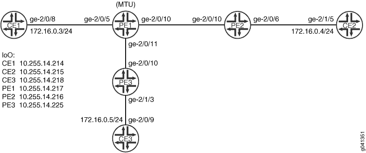 的基本 H-VPLS
示例显示了一个 MTU(设备 PE1)连接到两个 PE-r 设备(设备 PE2 和设备 PE3)。
设备 PE1 和设备 PE3 之间的伪线是主路径或工作路径。设备 PE1 和设备 PE2 之间的伪线是备用路径。
要支持带有 H-VPLS 的 VLAN,您必须在 MTU 设备的配置中包含该 output-vlan-map swap 语句,作为防止 VLAN ID 不匹配的变通方法。否则,PE-r 设备将报告 VLAN ID 不匹配,如下所示:
user@PE2> show vpls connections
Layer-2 VPN connections:

Legend for connection status (St)
EI -- encapsulation invalid      NC -- interface encapsulation not CCC/TCC/VPLS
EM -- encapsulation mismatch     WE -- interface and instance encaps not same
VC-Dn -- Virtual circuit down    NP -- interface hardware not present
CM -- control-word mismatch      -> -- only outbound connection is up
CN -- circuit not provisioned    <- -- only inbound connection is up
OR -- out of range               Up -- operational
OL -- no outgoing label          Dn -- down
LD -- local site signaled down   CF -- call admission control failure
RD -- remote site signaled down  SC -- local and remote site ID collision
LN -- local site not designated  LM -- local site ID not minimum designated
RN -- remote site not designated RM -- remote site ID not minimum designated
XX -- unknown connection status  IL -- no incoming label
MM -- MTU mismatch               MI -- Mesh-Group ID not available
BK -- Backup connection          ST -- Standby connection
PF -- Profile parse failure      PB -- Profile busy
RS -- remote site standby        SN -- Static Neighbor
LB -- Local site not best-site   RB -- Remote site not best-site
VM -- VLAN ID mismatch

Legend for interface status
Up -- operational
Dn -- down

Instance: customer
  VPLS-id: 601
    Neighbor                  Type  St     Time last up          # Up trans
    10.255.14.217(vpls-id 601) rmt  VM
配置
过程
CLI 快速配置
要快速配置此示例,请复制以下命令,将其粘贴到文本文件中,删除所有换行符,更改详细信息,以便与网络配置匹配,然后将命令复制并粘贴到层次结构级别的 [edit] CLI 中。
设备 PE1
set interfaces ge-2/0/5 vlan-tagging
set interfaces ge-2/0/5 encapsulation vlan-ccc
set interfaces ge-2/0/5 unit 601 encapsulation vlan-ccc
set interfaces ge-2/0/5 unit 601 vlan-id 601
set interfaces ge-2/0/5 unit 601 output-vlan-map swap
set interfaces ge-2/0/5 unit 601 family ccc
set interfaces ge-2/0/10 unit 0 family inet address 192.0.2.2/24
set interfaces ge-2/0/10 unit 0 family iso
set interfaces ge-2/0/10 unit 0 family mpls
set interfaces ge-2/0/11 unit 0 family inet address 192.0.2.3/24
set interfaces ge-2/0/11 unit 0 family iso
set interfaces ge-2/0/11 unit 0 family mpls
set interfaces lo0 unit 0 family inet address 10.255.14.217/32
set interfaces lo0 unit 0 family iso address 49.0001.0102.5501.4217.00
set protocols mpls interface ge-2/0/10.0
set protocols mpls interface ge-2/0/11.0
set protocols isis level 1 disable
set protocols isis interface ge-2/0/10.0
set protocols isis interface ge-2/0/11.0
set protocols isis interface lo0.0
set protocols ldp interface ge-2/0/10.0
set protocols ldp interface ge-2/0/11.0
set protocols ldp interface lo0.0
set protocols l2circuit neighbor 10.255.14.225 interface ge-2/0/5.601 virtual-circuit-id 601
set protocols l2circuit neighbor 10.255.14.225 interface ge-2/0/5.601 encapsulation-type ethernet-vlan
set protocols l2circuit neighbor 10.255.14.225 interface ge-2/0/5.601 backup-neighbor 10.255.14.216 standby
set routing-options router-id 10.255.14.217
设备 PE2
set interfaces ge-2/0/6 vlan-tagging
set interfaces ge-2/0/6 encapsulation vlan-vpls
set interfaces ge-2/0/6 unit 601 encapsulation vlan-vpls
set interfaces ge-2/0/6 unit 601 vlan-id 601
set interfaces ge-2/0/6 unit 601 family vpls
set interfaces ge-2/0/10 unit 0 family inet address 192.0.2.4/24
set interfaces ge-2/0/10 unit 0 family iso
set interfaces ge-2/0/10 unit 0 family mpls
set interfaces lo0 unit 0 family inet address 10.255.14.216/32
set interfaces lo0 unit 0 family iso address 49.0001.0102.5501.4216.00
set protocols mpls interface ge-2/0/10.0
set protocols isis level 1 disable
set protocols isis interface ge-2/0/10.0
set protocols isis interface lo0.0
set protocols ldp interface ge-2/0/10.0
set protocols ldp interface lo0.0
set routing-instances customer instance-type vpls
set routing-instances customer interface ge-2/0/6.601
set routing-instances customer protocols vpls vpls-id 601
set routing-instances customer protocols vpls neighbor 10.255.14.217 encapsulation-type ethernet-vlan
set routing-options router-id 10.255.14.216
设备 PE3
set interfaces ge-2/0/10 unit 0 family inet address 192.0.2.5/24
set interfaces ge-2/0/10 unit 0 family iso
set interfaces ge-2/0/10 unit 0 family mpls
set interfaces ge-2/1/3 vlan-tagging
set interfaces ge-2/1/3 encapsulation vlan-vpls
set interfaces ge-2/1/3 unit 601 encapsulation vlan-vpls
set interfaces ge-2/1/3 unit 601 vlan-id 601
set interfaces ge-2/1/3 unit 601 family vpls
set interfaces lo0 unit 0 family inet address 10.255.14.225/32
set interfaces lo0 unit 0 family iso address 49.0001.0102.5501.4225.00
set protocols mpls interface ge-2/0/10.0
set protocols isis level 1 disable
set protocols isis interface ge-2/0/10.0
set protocols isis interface lo0.0
set protocols ldp interface ge-2/0/10.0
set protocols ldp interface lo0.0
set routing-instances customer instance-type vpls
set routing-instances customer interface ge-2/1/3.601
set routing-instances customer protocols vpls vpls-id 601
set routing-instances customer protocols vpls neighbor 10.255.14.217 encapsulation-type ethernet-vlan
set routing-options router-id 10.255.14.225
设备 CE1
set interfaces ge-2/0/8 vlan-tagging
set interfaces ge-2/0/8 unit 601 vlan-id 601
set interfaces ge-2/0/8 unit 601 family inet address 172.16.0.3/24
set interfaces lo0 unit 0 family inet address 10.255.14.214/32
set protocols ospf area 0.0.0.0 interface lo0.0 passive
set protocols ospf area 0.0.0.0 interface ge-2/0/8.601
设备 CE2
set interfaces ge-2/1/5 vlan-tagging
set interfaces ge-2/1/5 unit 601 vlan-id 601
set interfaces ge-2/1/5 unit 601 family inet address 172.16.0.4/24
set interfaces lo0 unit 0 family inet address 10.255.14.215/32
set protocols ospf area 0.0.0.0 interface lo0.0 passive
set protocols ospf area 0.0.0.0 interface ge-2/1/5.601
设备 CE3
set interfaces ge-2/0/9 vlan-tagging
set interfaces ge-2/0/9 unit 601 vlan-id 601
set interfaces ge-2/0/9 unit 601 family inet address 172.16.0.5/24
set interfaces lo0 unit 0 family inet address 10.255.14.218/32
set protocols ospf area 0.0.0.0 interface lo0.0 passive
set protocols ospf area 0.0.0.0 interface ge-2/0/9.601
分步程序
下面的示例要求您在各个配置层级中进行导航。有关导航 CLI 的信息,请参阅 《CLI 用户指南》中的在配置模式下使用 CLI 编辑器。
要在 MTU 设备上配置 H-VPLS,请执行以下操作:
-
配置接口。
在连接到客户边缘的 MTU 设备接口上,配置其中一种电路交叉连接 (CCC) 封装类型和 CCC 地址族。这将启用第 2 层电路。
在面向核心的接口上,启用 MPLS 标签。面向核心的接口上也需要 ISO 地址,因为核心中使用了 IS-IS。
[edit interfaces]
user@PE1# set ge-2/0/5 vlan-tagging
user@PE1# set ge-2/0/5 encapsulation vlan-ccc
user@PE1# set ge-2/0/5 unit 601 family ccc
user@PE1# set ge-2/0/5 unit 601 encapsulation vlan-ccc
user@PE1# set ge-2/0/5 unit 601 vlan-id 601
user@PE1# set ge-2/0/5 unit 601 output-vlan-map swap
user@PE1# set ge-2/0/10 unit 0 family inet address 192.0.2.2/24
user@PE1# set ge-2/0/10 unit 0 family iso
user@PE1# set ge-2/0/10 unit 0 family mpls
user@PE1# set ge-2/0/11 unit 0 family inet address 192.0.2.3/24
user@PE1# set ge-2/0/11 unit 0 family iso
user@PE1# set ge-2/0/11 unit 0 family mpls
user@PE1# set lo0 unit 0 family inet address 10.255.14.217/32
user@PE1# set lo0 unit 0 family iso address 49.0001.0102.5501.4217.00
-
在接口上启用 MPLS 和 LDP。
在连接到其他 PE 设备的 MTU 设备接口上,配置 MPLS 和 LDP。
[edit protocols mpls]
user@PE1# set interface ge-2/0/10.0
user@PE1# set interface ge-2/0/11.0
[edit protocols ldp ]
user@PE1# set interface ge-2/0/10.0
user@PE1# set interface ge-2/0/11.0
user@PE1# set interface lo0.0
-
在接口上启用路由。
在连接到其他 PE 设备的 MTU 设备接口上,配置内部网关协议 (IGP),如 OSPF 或 IS-IS。
[edit protocols isis]
user@PE1# set level 1 disable
user@PE1# set interface ge-2/0/10.0
user@PE1# set interface ge-2/0/11.0
user@PE1# set interface lo0.0
-
配置第 2 层电路。
邻接方 10.255.14.225 是设备 PE3 的环路接口地址。这将设置工作路径。
邻接方 10.255.14.216 是设备 PE2 的环路接口地址。这将设置备份路径。
虚拟电路 ID 必须与设备 PE2 和设备 PE3 上配置的 VPLS ID 匹配。
[edit protocols l2circuit neighbor 10.255.14.225 interface ge-2/0/5.601]
user@PE1# set virtual-circuit-id 601
user@PE1# set encapsulation-type ethernet-vlan
user@PE1# set backup-neighbor 10.255.14.216 standby
-
配置路由器 ID。
[edit routing-options]
user@PE1# set router-id 10.255.14.217
分步程序
下面的示例要求您在各个配置层级中进行导航。有关导航 CLI 的信息,请参阅 《CLI 用户指南》中的在配置模式下使用 CLI 编辑器。
要在 MTU 设备上配置 H-VPLS,请执行以下操作:
配置接口。
在连接到客户边缘的 PE-r 设备接口上,配置其中一种 VPLS 封装类型和 VPLS 地址族。这样就能启用 VPLS。
在面向核心的接口上,启用 MPLS 标签。面向核心的接口上也需要 ISO 地址,因为核心中使用了 IS-IS。
[edit interfaces]
user@PE2# set ge-2/0/6 vlan-tagging
user@PE2# set ge-2/0/6 encapsulation vlan-vpls
user@PE2# set ge-2/0/6 unit 601 encapsulation vlan-vpls
user@PE2# set ge-2/0/6 unit 601 vlan-id 601
user@PE2# set ge-2/0/6 unit 601 family vpls
user@PE2# set ge-2/0/10 unit 0 family inet address 192.0.2.4/24
user@PE2# set ge-2/0/10 unit 0 family iso
user@PE2# set ge-2/0/10 unit 0 family mpls
user@PE2# set lo0 unit 0 family inet address 10.255.14.216/32
user@PE2# set lo0 unit 0 family iso address 49.0001.0102.5501.4216.00
在接口上启用 MPLS 和 LDP。
在连接到其他 PE 设备的 MTU 设备接口上,配置 MPLS 和 LDP。
[edit protocols mpls]
user@PE2# set interface ge-2/0/10.0
[edit protocols ldp ]
user@PE2# set interface ge-2/0/10.0
user@PE2# set interface lo0.0
在接口上启用路由。
在连接到其他 PE 设备的 MTU 设备接口上,配置内部网关协议 (IGP),如 OSPF 或 IS-IS。
[edit protocols isis]
user@PE2# set level 1 disable
user@PE2# set interface ge-2/0/10.0
user@PE2# set interface lo0.0
配置 VPLS。
该
neighbor 10.255.14.217语句指向设备 PE1 的环路接口地址。VPLS ID 必须与在 MTU(设备 PE1)上配置的虚拟电路 ID 匹配。
[edit routing-instances customer]
user@PE2# set instance-type vpls
user@PE2# set interface ge-2/0/6.601
user@PE2# set protocols vpls vpls-id 601
user@PE2# set protocols vpls neighbor 10.255.14.217 encapsulation-type ethernet-vlan
配置路由器 ID。
[edit routing-options]
user@PE2# set router-id 10.255.14.216
结果
在配置模式下,输入 show interfaces、 show protocols、 show routing-instances和 show routing-options 命令以确认您的配置。如果输出未显示预期的配置,请重复此示例中的说明以更正配置。
设备 PE1
user@PE1# show interfaces
ge-2/0/5 {
    vlan-tagging;
    encapsulation vlan-ccc;
    unit 601 {
        encapsulation vlan-ccc;
        vlan-id 601;
        output-vlan-map swap;
        family ccc;
    }
}
ge-2/0/10 {
    unit 0 {
        family inet {
            address 192.0.2.2/24;
        }
        family iso;
        family mpls;
    }
}
ge-2/0/11 {
    unit 0 {
        family inet {
            address 192.0.2.3/24;
        }
        family iso;
        family mpls;
    }
}
lo0 {
    unit 0 {
        family inet {
            address 10.255.14.217/32;
        }
        family iso {
            address 49.0001.0102.5501.4217.00;
        }
    }
}
user@PE1# show protocols
mpls {
    interface ge-2/0/10.0;
    interface ge-2/0/11.0;
}
isis {
    level 1 disable;
    interface ge-2/0/10.0;
    interface ge-2/0/11.0;
    interface lo0.0;
}
ldp {
    interface ge-2/0/10.0;
    interface ge-2/0/11.0;
    interface lo0.0;
}
l2circuit {
    neighbor 10.255.14.225 {
        interface ge-2/0/5.601 {
            virtual-circuit-id 601;
            encapsulation-type ethernet-vlan;
            backup-neighbor 10.255.14.216 {
                standby;
            }
        }
    }
}
user@PE1# show routing-options
router-id 10.255.14.217;
设备 PE2
user@PE2# show interfaces
ge-2/0/6 {
    vlan-tagging;
    encapsulation vlan-vpls;
    unit 601 {
        encapsulation vlan-vpls;
        vlan-id 601;
        family vpls;
    }
}
ge-2/0/10 {
    unit 0 {
        family inet {
            address 192.0.2.4/24;
        }
        family iso;
        family mpls;
    }
}
lo0 {
    unit 0 {
        family inet {
            address 10.255.14.216/32;
        }
        family iso {
            address 49.0001.0102.5501.4216.00;
        }
    }
}
user@PE2# show protocols
mpls {
    interface ge-2/0/10.0;
}
isis {
    level 1 disable;
    interface ge-2/0/10.0;
    interface lo0.0;
}
ldp {
    interface ge-2/0/10.0;
    interface lo0.0;
}
user@PE2# show routing-instances
customer {
    instance-type vpls;
    interface ge-2/0/6.601;
    protocols {
        vpls {
            vpls-id 601;
            neighbor 10.255.14.217 {
                encapsulation-type ethernet-vlan;
            }
        }
    }
}
user@PE2# show routing-options
router-id 10.255.14.216;
如果完成设备配置,请从配置模式进入。commit
验证
确认配置工作正常。
验证第 2 层电路
目的
验证第 2 层电路在 MTU 设备上是否正常运行。
行动
在操作模式下,输入命令 show l2circuit connections 。
user@PE1> show l2circuit connections
Layer-2 Circuit Connections:

Legend for connection status (St)
EI -- encapsulation invalid      NP -- interface h/w not present
MM -- mtu mismatch               Dn -- down
EM -- encapsulation mismatch     VC-Dn -- Virtual circuit Down
CM -- control-word mismatch      Up -- operational
VM -- vlan id mismatch           CF -- Call admission control failure
OL -- no outgoing label          IB -- TDM incompatible bitrate
NC -- intf encaps not CCC/TCC    TM -- TDM misconfiguration
BK -- Backup Connection          ST -- Standby Connection
CB -- rcvd cell-bundle size bad  SP -- Static Pseudowire
LD -- local site signaled down   RS -- remote site standby
RD -- remote site signaled down  XX -- unknown

Legend for interface status
Up -- operational
Dn -- down
Neighbor: 10.255.14.216
    Interface                 Type  St     Time last up          # Up trans
    ge-2/0/5.601(vc 601)      rmt   Up     Oct  9 16:28:58 2012           1
      Remote PE: 10.255.14.216, Negotiated control-word: No
      Incoming label: 299904, Outgoing label: 800001
      Negotiated PW status TLV: No
      Local interface: ge-2/0/5.601, Status: Up, Encapsulation: VLAN
Neighbor: 10.255.14.225
    Interface                 Type  St     Time last up          # Up trans
    ge-2/0/5.601(vc 601)      rmt   ST
意义
正如预期一样,与设备 PE3 的第 2 层电路连接可以运行,并且与设备 PE2 的连接处于待机模式。
检查 VPLS 连接
目的
验证 VPLS 连接在 PE-r 设备上是否正常工作。
行动
在操作模式下,输入命令 show vpls connections 。
user@PE2> show vpls connections

Layer-2 VPN connections:

Legend for connection status (St)
EI -- encapsulation invalid      NC -- interface encapsulation not CCC/TCC/VPLS
EM -- encapsulation mismatch     WE -- interface and instance encaps not same
VC-Dn -- Virtual circuit down    NP -- interface hardware not present
CM -- control-word mismatch      -> -- only outbound connection is up
CN -- circuit not provisioned    <- -- only inbound connection is up
OR -- out of range               Up -- operational
OL -- no outgoing label          Dn -- down
LD -- local site signaled down   CF -- call admission control failure
RD -- remote site signaled down  SC -- local and remote site ID collision
LN -- local site not designated  LM -- local site ID not minimum designated
RN -- remote site not designated RM -- remote site ID not minimum designated
XX -- unknown connection status  IL -- no incoming label
MM -- MTU mismatch               MI -- Mesh-Group ID not available
BK -- Backup connection          ST -- Standby connection
PF -- Profile parse failure      PB -- Profile busy
RS -- remote site standby        SN -- Static Neighbor
LB -- Local site not best-site   RB -- Remote site not best-site
VM -- VLAN ID mismatch

Legend for interface status
Up -- operational
Dn -- down

Instance: customer
  VPLS-id: 601
    Neighbor                  Type  St     Time last up          # Up trans
    10.255.14.217(vpls-id 601) rmt  Up     Oct  9 16:29:02 2012           1
      Remote PE: 10.255.14.217, Negotiated control-word: No
      Incoming label: 800001, Outgoing label: 299904
      Negotiated PW status TLV: No
      Local interface: vt-2/0/10.84934914, Status: Up, Encapsulation: VLAN
        Description: Intf - vpls customer neighbor 10.255.14.217 vpls-id 601
user@PE3> show vpls connections
Layer-2 VPN connections:

Legend for connection status (St)
EI -- encapsulation invalid      NC -- interface encapsulation not CCC/TCC/VPLS
EM -- encapsulation mismatch     WE -- interface and instance encaps not same
VC-Dn -- Virtual circuit down    NP -- interface hardware not present
CM -- control-word mismatch      -> -- only outbound connection is up
CN -- circuit not provisioned    <- -- only inbound connection is up
OR -- out of range               Up -- operational
OL -- no outgoing label          Dn -- down
LD -- local site signaled down   CF -- call admission control failure
RD -- remote site signaled down  SC -- local and remote site ID collision
LN -- local site not designated  LM -- local site ID not minimum designated
RN -- remote site not designated RM -- remote site ID not minimum designated
XX -- unknown connection status  IL -- no incoming label
MM -- MTU mismatch               MI -- Mesh-Group ID not available
BK -- Backup connection          ST -- Standby connection
PF -- Profile parse failure      PB -- Profile busy
RS -- remote site standby        SN -- Static Neighbor
LB -- Local site not best-site   RB -- Remote site not best-site
VM -- VLAN ID mismatch

Legend for interface status
Up -- operational
Dn -- down

Instance: customer
  VPLS-id: 601
    Neighbor                  Type  St     Time last up          # Up trans
    10.255.14.217(vpls-id 601) rmt  Up     Oct  9 16:29:02 2012           1
      Remote PE: 10.255.14.217, Negotiated control-word: No
      Incoming label: 800001, Outgoing label: 299920
      Negotiated PW status TLV: No
      Local interface: vt-2/0/10.68157698, Status: Up, Encapsulation: VLAN
        Description: Intf - vpls customer neighbor 10.255.14.217 vpls-id 601
意义
正如预期一样,VPLS 连接在两个 PE-r 设备上均正常运行。
检查连接
目的
验证设备 CE1 是否可以 ping 设备 CE3。
行动
user@CE1> ping 10.255.14.218
PING 10.255.14.218 (10.255.14.218): 56 data bytes
64 bytes from 10.255.14.218: icmp_seq=0 ttl=64 time=0.858 ms
64 bytes from 10.255.14.218: icmp_seq=1 ttl=64 time=0.527 ms
64 bytes from 10.255.14.218: icmp_seq=2 ttl=64 time=0.670 ms
^C
--- 10.255.14.218 ping statistics ---
3 packets transmitted, 3 packets received, 0% packet loss
round-trip min/avg/max/stddev = 0.527/0.685/0.858/0.136 ms
意义
输出显示 H-VPLS 已正常运行。
手动触发从有源伪线到冗余伪线的切换
目的
确保设备 PE1 与设备 PE2 之间的伪线已正常运行。
行动
user@CE1> request l2circuit-switchover virtual-circuit-id 601 neighbor 10.255.14.225
user@CE1> ping 10.255.14.215
PING 10.255.14.215 (10.255.14.215): 56 data bytes
64 bytes from 10.255.14.215: icmp_seq=0 ttl=64 time=0.738 ms
64 bytes from 10.255.14.215: icmp_seq=1 ttl=64 time=0.627 ms
64 bytes from 10.255.14.215: icmp_seq=2 ttl=64 time=0.629 ms
^C
--- 10.255.14.215 ping statistics ---
3 packets transmitted, 3 packets received, 0% packet loss
round-trip min/avg/max/stddev = 0.627/0.665/0.738/0.052 ms
意义
从设备 CE1 到设备 CE2 的成功 ping 表示设备 PE1 和 PE2 之间的伪线正常运行。现在,如果从设备 CE1 对设备 CE3 使用 Ping 命令,则 ping 应会失败。