本页内容
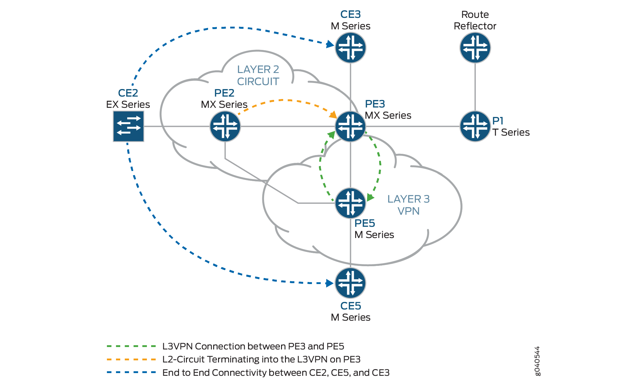
示例:将第 2 层电路与第 3 层 VPN 互连
此示例提供配置和验证第 2 层电路到第 3 层 VPN 互连的分步过程和命令。它包含以下部分:
要求
此示例使用以下硬件和软件组件:
Junos OS 9.3 或更高版本
3 个 MX 系列 5G 通用路由平台
1 M Series 多服务边缘路由器
1 T Series 核心路由器
1 EX 系列以太网交换机
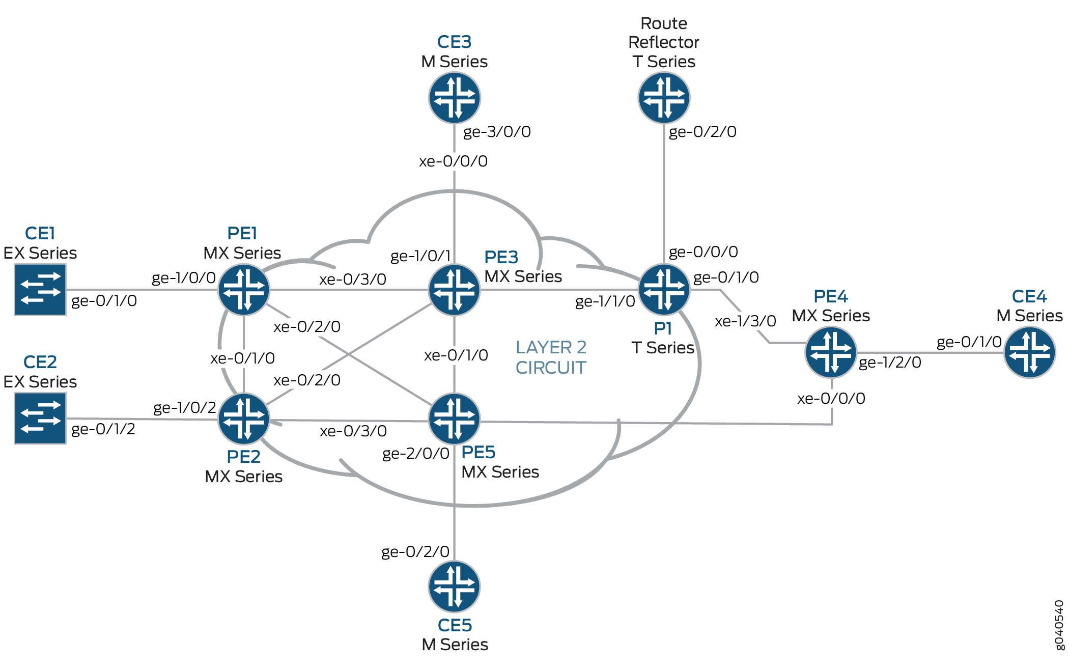
概述和拓扑
配置
在任何配置会话中,最好定期验证是否可以使用命令提交 commit check 配置。
在此示例中,使用以下命令提示符标识要配置的路由器:
CE2标识客户边缘 2 (CE2) 路由器PE1标识提供商边缘 1 (PE1) 路由器CE3标识客户边缘 3 (CE3) 路由器PE3标识提供商边缘 3 (PE3) 路由器CE5标识客户边缘 5 (CE5) 路由器PE5标识提供商边缘 5 (PE5) 路由器
此示例包含以下过程:
配置面向客户的环路接口 PE 路由器
分步程序
要开始构建互连,请在 PE 路由器上配置接口。如果您的网络包含提供商 (P) 路由器,请同时配置 P 路由器上的接口。此示例显示了路由器 PE2、路由器 PE3 和路由器 PE5 的配置。
在路由器 PE2 上,配置
ge-1/0/2接口封装。要配置接口封装,请包含encapsulation该语句并指定ethernet-ccc选项(vlan-ccc还支持封装)。为电路交叉连接功能配置ge-1/0/2.0逻辑接口家族。要配置逻辑接口家族,请包含family该语句并指定该ccc选项。对于第 2 层电路域中的所有路由器,封装配置方法应相同。[edit interfaces] ge-1/0/2 { encapsulation ethernet-ccc; unit 0 { family ccc; } }在路由器 PE2 上,配置
lo0.0接口。包括family该语句并指定该inet选项。包括该address语句并指定192.0.2.2/24为环路 IPv4 地址。[edit interfaces] lo0 { unit 0 { family inet { address 192.0.2.2/24; } } }在路由器 PE3 上,配置
ge-1/0/1接口。包括family该语句并指定该inet选项。包括该address语句并指定198.51.100.1/24为此设备的接口地址。[edit interfaces] ge-1/0/1 { unit 0 { family inet { address 198.51.100.1/24; } } }在路由器 PE3 上,配置
lo0.0环路接口。包括family该语句并指定该inet选项。包括该address语句并指定192.0.2.3/24为此路由器的环路 IPv4 地址。[edit interfaces] lo0 { unit 0 { family inet { address 192.0.2.3/24; } } }在路由器 PE5 上,配置
ge-2/0/0接口。包括family该语句并指定该inet选项。包括该address语句并指定198.51.100.8/24为接口地址。[edit interfaces] ge-2/0/0 { unit 0 { family inet { address 198.51.100.8/24; } } }在路由器 PE5 上,配置
lo0.0接口。包括family该语句并指定该inet选项。包括该address语句并指定192.0.2.5/24为此路由器的环路 IPv4 地址。[edit interfaces] lo0 { unit 0 { family inet { address 192.0.2.5/24; } } }
配置面向核心的接口
分步程序
此过程介绍如何在 PE 路由器上配置面向核心的接口。此示例不包括物理拓扑图中显示的所有面向核心的接口。在面向核心的接口上启用和mplsinet地址族。
在路由器 PE2 上,配置
xe-0/2/0接口。包括family该语句并指定inet地址族。包括该address语句并指定10.10.5.1/30为接口地址。包括family该语句并指定mpls地址族。[edit interfaces] xe-0/2/0 { unit 0 { family inet { address 10.10.5.1/30; } family mpls; } }在路由器 PE3 上,配置面向核心的接口。包括
family该语句并指定inet地址族。包括address该语句,并将示例中显示的 IPv4 地址指定为接口地址。包括family该语句并指定mpls地址族。在此示例中,xe-2/1/0接口连接到路由器 PE5,接口xe-2/2/0连接到路由器 PE2。[edit interfaces] xe-2/0/0 { unit 0 { family inet { address 10.10.20.2/30; } family mpls; } } xe-2/1/0 { unit 0 { family inet { address 10.10.6.1/30; } family mpls; } } xe-2/2/0 { unit 0 { family inet { address 10.10.5.2/30; } family mpls; } } xe-2/3/0 { unit 0 { family inet { address 10.10.1.2/30; } family mpls; } }在路由器 PE5 上,配置
xe-0/1/0接口。包括family该语句并指定inet地址族。包括该address语句并指定10.10.6.2/30为接口地址。包括family该语句并指定mpls地址族。[edit interfaces] xe-0/1/0 { unit 0 { family inet { address 10.10.6.2/30; } family mpls; } }
配置协议
分步程序
此过程介绍如何配置此示例中使用的协议。如果您的网络包含 P 路由器,也请配置 P 路由器上的接口。
在路由器 PE3 上,启用 OSPF 作为 IGP。在除 以外的所有接口
fxp.0上启用 MPLS、LDP 和 BGP 协议。LDP 用作路由器 PE2 的第 2 层电路的信令协议。以下配置片段显示路由器 PE3 的协议配置:[edit] protocols { rsvp { interface all; interface fxp0.0 { disable; } } mpls { label-switched-path to-RR { to 192.0.2.7; } label-switched-path to-PE2 { to 192.0.2.2; } label-switched-path to-PE5 { to 192.0.2.5; } label-switched-path to-PE4 { to 192.0.2.4; } label-switched-path to-PE1 { to 192.0.2.1; } interface all; interface fxp0.0 { disable; } } bgp { group RR { type internal; local-address 192.0.2.3; family inet-vpn { unicast; } family l2vpn { signaling; } neighbor 192.0.2.7; } } ospf { traffic-engineering; area 0.0.0.0 { interface all; interface fxp0.0 { disable; } } } ldp { interface all; interface fxp0.0 { disable; } } }在路由器 PE2 上,配置 MPLS、OSPF 和 LDP 协议。
[edit ]
protocols {
    mpls {
        interface all;
        interface fxp0.0 {
            disable;
        }
    }
    ospf {
        traffic-engineering;
        area 0.0.0.0 {
            interface all;
            interface fxp0.0 {
                disable;
            }
        }
    }
    ldp {
        interface all;
        interface fxp0.0 {
            disable;
        }
    }
}
在路由器 PE5 上,启用 OSPF 作为 IGP。在除 之外的所有接口
fxp.0上启用 MPLS、RSVP 和 BGP 协议。通过 和inet地址家族启用mpls面向核心的接口。[edit] protocols { rsvp { interface all { link-protection; } interface fxp0.0 { disable; } } mpls { label-switched-path to-RR { to 192.0.2.7; } label-switched-path to-PE2 { to 192.0.2.2; } label-switched-path to-PE3 { to 192.0.2.3; } label-switched-path to-PE4 { to 192.0.2.4; } label-switched-path to-PE1 { to 192.0.2.1; } interface all; interface fxp0.0 { disable; } } bgp { group to-rr { type internal; local-address 192.0.2.5; family inet-vpn { unicast; } family l2vpn { signaling; } neighbor 192.0.2.7; } } ospf { traffic-engineering; area 0.0.0.0 { interface all; interface fxp0.0 { disable; } } } }
配置路由实例和第 2 层电路
分步程序
此过程介绍如何配置第 2 层电路和第 3 层 VPN。
在路由器 PE2 上,配置第 2 层电路。包括该
l2circuit语句。包含该neighbor语句,并将路由器 PE3 的环路 IPv4 地址指定为邻接方。包括 interface 语句并指定ge-1/0/2.0为参与第 2 层电路的逻辑接口。包括该virtual-circuit-id语句并指定100作为标识符。包括no-control-word不支持控制字的设备的语句。[edit ] protocols { l2circuit { neighbor 192.0.2.3 { interface ge-1/0/2.0 { virtual-circuit-id 100; no-control-word; } } } }在路由器 PE3 上,将第 2 层电路配置为路由器 PE2。包括该
l2circuit语句。包括该neighbor语句,并将路由器 PE2 的环路 IPv4 地址指定为邻接方。包括 interface 语句,并指定lt-1/1/10.0为参与第 2 层电路的逻辑隧道接口。包括该virtual-circuit-id语句并指定100作为标识符。包括该no-control-word语句。[edit ] protocols { l2circuit { neighbor 192.0.2.2 { interface lt-1/1/10.0 { virtual-circuit-id 100; no-control-word; } } } }在路由器 PE3 上,在层次结构级别将
[edit routing-instances]第 3 层 VPN (L3VPN) 路由实例配置为路由器 PE5。此外,还要在层次结构级别配置[edit routing-instances L3VPN protocols]BGP 对等体组。[edit ] routing-instances { L3VPN { instance-type vrf; interface ge-1/0/1.0; interface lt-1/1/10.1; route-distinguisher 65000:33; vrf-target target:65000:2; vrf-table-label; protocols { bgp { export direct; group ce3 { neighbor 198.51.100.6{ peer-as 100; } } } } } }在路由器 PE5 上,在层次结构级别配置
[edit routing-instances]第 3 层 VPN 路由实例 (L3VPN)。此外,还要在层次结构级别配置[edit routing-instances L3VPN protocols]BGP 对等体组。[edit ] routing-instances { L3VPN { instance-type vrf; interface ge-2/0/0.0; route-distinguisher 65000:5; vrf-target target:65000:2; vrf-table-label; protocols { bgp { group ce5 { neighbor 198.51.100.10 { peer-as 200; } } } } } }
配置路由反射器
分步程序
虽然第 2 层电路与第 3 层 VPN 互连不需要路由反射器,但此示例使用路由反射器。此过程显示路由反射器配置的相关部分。
使用 RSVP、MPLS、BGP 和 OSPF 配置路由反射器。路由反射器是与 PE 路由器的 BGP 对等体。请注意,BGP 对等体组配置包含该
family语句,并指定inet-vpn选项 该inet-vpn选项使 BGP 能够通告第 3 层 VPN 路由的网络层可达性信息 (NLRI)。该配置还包括语family句并指定选项l2vpn。该l2vpn选项使 BGP 能够为第 2 层电路播发 NLRI。第 2 层电路使用与第 2 层 VPN 相同的内部 BGP 基础架构。[edit ] protocols { rsvp { interface all; interface fxp0.0 { disable; } } mpls { label-switched-path to-pe3 { to 192.0.2.3; } label-switched-path to-pe5 { to 192.0.2.5; } interface all; interface fxp0.0 { disable; } } bgp { group RR { type internal; local-address 192.0.2.7; family inet { unicast; } family inet-vpn { unicast; } family l2vpn { signaling; } cluster 192.0.2.7; neighbor 192.0.2.1; neighbor 192.0.2.2; neighbor 192.0.2.4; neighbor 192.0.2.5; neighbor 192.0.2.3; } } ospf { traffic-engineering; area 0.0.0.0 { interface all; interface fxp0.0 { disable; } } } }
将第 2 层电路与第 3 层 VPN 互连
分步程序
在MX 系列路由器中配置逻辑隧道接口之前,必须先创建用于隧道服务的隧道服务接口。
在路由器 PE3 上创建隧道服务接口。在层次结构级别包含
[edit chassis fpc slot-number pic slot-number tunnel-services]该bandwidth语句,并指定要为隧道服务预留的带宽量(以千兆位/秒为单位)。[edit chassis] fpc 1 { pic 1 { tunnel-services { bandwidth 1g; } } }在路由器 PE3 上,配置
lt-1/1/10逻辑隧道接口单元 0。路由器 PE3 是使用逻辑隧道接口将第 2 层电路拼 接 到第 3 层 VPN 的路由器。对等单元接口的配置是进行互连的要素。
包括
encapsulation该语句并指定该ethernet-ccc选项。包括该peer-unit语句,并将逻辑接口单元1指定为对等隧道接口。包括family该语句并指定该ccc选项。lt-1/1/10使用封装配置逻辑接口单元1ethernet。包括该peer-unit语句,并将逻辑接口单元0指定为对等隧道接口。包括family该语句并指定该inet选项。还要包含该address语句,并指定198.51.100.11/24接口的 IPv4 地址。注意:对等逻辑接口必须属于从隧道服务 PIC 派生的同一逻辑隧道接口。
[edit interfaces]
lt-1/1/10 {
    unit 0 {
        encapsulation ethernet-ccc;
        peer-unit 1;
        family ccc;
    }
    unit 1 {
        encapsulation ethernet;
        peer-unit 0;
        family inet {
            address 198.51.100.11/24;
        }
    }
}
在每个路由器上,提交配置。
user@host> commit check
configuration check succeeds
user@host> commit
验证第 2 层电路到第 3 层 VPN 互连
要验证互连是否正常工作,请执行以下任务:
- 验证与路由器 PE3 的第 2 层电路连接是否已开启
- 验证路由器 PE2 上的 LDP 邻接方和目标 LDP LSP
- 验证路由器 PE2 上的第 2 层电路路由
- 验证与路由器 PE2 的第 2 层电路连接是否已开启
- 验证路由器 PE3 上的 LDP 邻接方和目标 LDP LSP
- 通过路由器 PE3 上的路由反射器验证 BGP 对等会话
- 验证路由器 PE3 上的第 3 层 VPN 路由
- 验证路由器 PE3 上的第 2 层电路路由
- 验证路由器 PE3 上的 MPLS 路由
- 验证路由器 CE2 和路由器 CE3 之间的流量
- 验证路由器 CE2 和路由器 CE5 之间的流量
验证与路由器 PE3 的第 2 层电路连接是否已开启
目的
要验证从路由器 PE2 到路由器 PE3 的第 2 层电路连接是否为 Up。还要记录传入和传出 LDP 标签以及此第 2 层电路连接使用的电路 ID。
行动
使用 show l2circuit connections 命令验证第 2 层电路连接是否已开启。
user@PE2> show l2circuit connections
Legend for connection status (St)
EI -- encapsulation invalid      NP -- interface h/w not present
MM -- mtu mismatch               Dn -- down
EM -- encapsulation mismatch     VC-Dn -- Virtual circuit Down
CM -- control-word mismatch      Up -- operational
VM -- vlan id mismatch           CF -- Call admission control failure
OL -- no outgoing label          IB -- TDM incompatible bitrate
NC -- intf encaps not CCC/TCC    TM -- TDM misconfiguration
BK -- Backup Connection          ST -- Standby Connection
CB -- rcvd cell-bundle size bad  SP -- Static Pseudowire
LD -- local site signaled down   RS -- remote site standby
RD -- remote site signaled down  XX -- unknown

Legend for interface status
Up -- operational
Dn -- down
Neighbor: 192.0.2.3
    Interface                 Type  St     Time last up          # Up trans
    ge-1/0/2.0(vc 100)        rmt   Up     Jan  7 02:14:13 2010           1
      Remote PE: 192.0.2.3, Negotiated control-word: No
      Incoming label: 301488, Outgoing label: 315264
      Negotiated PW status TLV: No
      Local interface: ge-1/0/2.0, Status: Up, Encapsulation: ETHERNET
意义
输出显示,从路由器 PE2 到路由器 PE3 的第 2 层电路连接是 Up ,并且连接正在使用该 ge-1/0/2.0 接口。请注意,传出标签是 315264 ,传入标签是 301488,虚拟电路 (VC) 标识符是 100 ,封装为 ETHERNET。
验证路由器 PE2 上的 LDP 邻接方和目标 LDP LSP
目的
要验证路由器 PE2 是否具有到路由器 PE3 的目标 LDP LSP,以及路由器 PE2 和路由器 PE3 是否为 LDP 邻接方。
行动
使用 show ldp neighbor 命令验证路由器 PE2 是否具有到路由器 PE3 的目标 LDP LSP,以及路由器 PE2 和路由器 PE3 是否为 LDP 邻接方。
user@PE2> show ldp neighbor
Address            Interface          Label space ID         Hold time
192.0.2.3            lo0.0              192.0.2.3:0                38
意义
输出显示路由器 PE2 有一个 IPv4 地址 192.0.2.3为 的 LDP 邻接方。地址 192.0.2.3 是路由器 PE3 的 lo0.0 接口地址。请注意,路由器 PE2 使用 LSP 的本地 lo0.0 接口。
验证路由器是否为 LDP 邻接方还将验证目标 LSP 是否已建立。
验证路由器 PE2 上的第 2 层电路路由
目的
验证路由器 PE2 是否具有第 2 层电路的路由,以及路由是否使用到路由器 PE3 的 LDP MPLS 标签。
行动
验证路由器 PE2 是否具有第 2 层电路的路由,以及路由是否使用到路由器 PE3 show route table mpls.0 的 LDP MPLS 标签。
user@PE2> show route table mpls.0
mpls.0: 13 destinations, 13 routes (13 active, 0 holddown, 0 hidden)
+ = Active Route, - = Last Active, * = Both

0                  *[MPLS/0] 1w3d 05:24:11, metric 1
                      Receive
1                  *[MPLS/0] 1w3d 05:24:11, metric 1
                      Receive
2                  *[MPLS/0] 1w3d 05:24:11, metric 1
                      Receive
300560             *[LDP/9] 16:12:23, metric 1
                    > to 10.10.2.1 via xe-0/1/0.0, Pop
300560(S=0)        *[LDP/9] 16:12:23, metric 1
                    > to 10.10.2.1 via xe-0/1/0.0, Pop
301008             *[LDP/9] 16:12:23, metric 1
                    > to 10.10.4.2 via xe-0/3/0.0, Swap 299856
301488             *[L2CKT/7] 11:07:28
                    > via ge-1/0/2.0, Pop
301536             *[LDP/9] 16:12:23, metric 1
                    > to 10.10.4.2 via xe-0/3/0.0, Pop
301536(S=0)        *[LDP/9] 16:12:23, metric 1
                    > to 10.10.4.2 via xe-0/3/0.0, Pop
301712             *[LDP/9] 12:41:22, metric 1
                    > to 10.10.5.2 via xe-0/2/0.0, Swap 315184
301728             *[LDP/9] 12:41:22, metric 1
                    > to 10.10.5.2 via xe-0/2/0.0, Pop
301728(S=0)        *[LDP/9] 12:41:22, metric 1
                    > to 10.10.5.2 via xe-0/2/0.0, Pop
ge-1/0/2.0         *[L2CKT/7] 11:07:28, metric2 1
                    > to 10.10.5.2 via xe-0/2/0.0, Push 315264
意义
输出显示路由器 PE2 在路由出接口ge-1/0/2.0上L2CKT推315264送出标签。输出还显示路由器 PE2 在传入方接口上L2CKT弹出301488传入标签ge-1/0/2.0
验证与路由器 PE2 的第 2 层电路连接是否已开启
目的
要验证从路由器 PE3 到路由器 PE2 的第 2 层电路连接是否为 Up,还记录传入和传出 LDP 标签以及此第 2 层电路连接使用的电路 ID。
行动
使用 show l2circuit connections 命令验证第 2 层电路连接是否已开启。
user@PE3> show l2circuit connections
Layer-2 Circuit Connections:
Legend for connection status (St)
EI -- encapsulation invalid      NP -- interface h/w not present
MM -- mtu mismatch               Dn -- down
EM -- encapsulation mismatch     VC-Dn -- Virtual circuit Down
CM -- control-word mismatch      Up -- operational
VM -- vlan id mismatch           CF -- Call admission control failure
OL -- no outgoing label          IB -- TDM incompatible bitrate
NC -- intf encaps not CCC/TCC    TM -- TDM misconfiguration
BK -- Backup Connection          ST -- Standby Connection
CB -- rcvd cell-bundle size bad  XX -- unknown

Legend for interface status
Up -- operational
Dn -- down
Neighbor: 192.0.2.2
    Interface                 Type  St     Time last up          # Up trans
    lt-1/1/10.0(vc 100)       rmt   Up     Jan  7 02:15:03 2010           1
      Remote PE: 192.0.2.2, Negotiated control-word: No
      Incoming label: 315264, Outgoing label: 301488
      Local interface: lt-1/1/10.0, Status: Up, Encapsulation: ETHERNET
意义
输出显示,从路由器 PE3 到路由器 PE2 的第 2 层电路连接是 Up ,并且该连接正在使用逻辑隧道 (lt) 接口。请注意,传入标签为 315264 ,传出标签为 301488,虚拟电路 (VC) 标识符为 100,封装为 ETHERNET。
验证路由器 PE3 上的 LDP 邻接方和目标 LDP LSP
目的
要验证路由器 PE3 是否具有到路由器 PE2 的目标 LDP LSP,以及路由器 PE3 和路由器 PE2 是否为 LDP 邻接方。
行动
使用 show ldp neighbor 命令验证路由器 PE2 是否具有到路由器 PE3 的目标 LDP LSP,以及路由器 PE2 和路由器 PE3 是否为 LDP 邻接方。
user@PE2> show ldp neighbor
Address            Interface          Label space ID         Hold time
192.0.2.2            lo0.0              192.0.2.2:0                43
192.0.2.4            lo0.0              192.0.2.4:0                33
意义
输出显示路由器 PE3 有一个 IPv4 地址 192.0.2.2为 的 LDP 邻接方。地址 192.0.2.2 是路由器 PE2 的 lo0.0 接口地址。输出还显示路由器 PE3 上用于 LSP 的接口为 lo0.0。验证路由器是否为 LDP 邻接方还将验证目标 LSP 是否已建立。
通过路由器 PE3 上的路由反射器验证 BGP 对等会话
目的
验证路由器 PE3 是否具有与路由反射器建立的对等会话。
行动
使用命令 show bgp summary 验证路由器 PE3 是否已与路由反射器建立对等会话。
user@PE2> show bgp summary
Groups: 2 Peers: 2 Down peers: 0
Table          Tot Paths  Act Paths Suppressed    History Damp State    Pending
bgp.l3vpn.0            1          1          0          0          0          0
Peer                     AS      InPkt     OutPkt    OutQ   Flaps Last Up/Dwn State|#Active/Received/Accepted/Damped...
192.0.2.7               65000       1597       1612       0       1    12:03:21 Establ
  bgp.l2vpn.0: 0/0/0/0
  bgp.l3vpn.0: 1/1/1/0
  L3VPN.inet.0: 1/1/1/0
意义
输出显示路由器 PE3 与 IPv4 地址 192.0.2.7为 的路由器存在对等会话。地址 192.0.2.7 是路由反射器的 lo0.0 接口地址。输出还显示对等会话状态为 Establ,表示会话已建立。
验证路由器 PE3 上的第 3 层 VPN 路由
目的
验证路由器 PE3 是否具有到路由器 CE2、路由器 CE3 和路由器 CE5 的第 3 层 VPN 路由。
行动
使用命令 show route table L3VPN.inet.0 验证路由器 PE3 是否具有到第 3 层 VPN 路由表中的路由器 CE2、路由器 CE3 和路由器 CE5 的路由。在此示例中, L3VPN 是为路由实例配置的名称。
user@PE3> show route table L3VPN.inet.0
L3VPN.inet.0: 5 destinations, 5 routes (5 active, 0 holddown, 0 hidden)
+ = Active Route, - = Last Active, * = Both

198.51.100.10/24      *[Direct/0] 11:13:59
                    > via lt-1/1/10.1
198.51.100.11/24      *[Local/0] 11:13:59
                      Local via lt-1/1/10.1
198.51.100.12/24      *[BGP/170] 11:00:41, localpref 100, from 192.0.2.7
                      AS path: I
                    > to 10.10.6.2 via xe-2/1/0.0, Push 16
198.51.100.13/24      *[Direct/0] 11:54:41
                    > via ge-1/0/1.0
198.51.100.1/24      *[Local/0] 11:54:41
                      Local via ge-1/0/1.0
意义
输出显示路由器 PE3 的路由到 IPv4 子网地址 198.51.100.10。地址 198.51.100.15 是路由器 CE2 的接口地址。输出显示路由器 PE3 的路由到 IPv4 子网地址 198.51.100.12。地址 198.51.100.10 是路由器 CE5 的接口地址。输出显示路由器 PE3 的路由到 IPv4 子网地址 198.51.100.13。地址 198.51.100.6 是路由器 CE3 的接口地址。
验证路由器 PE3 上的第 2 层电路路由
目的
验证路由器 PE3 在第 2 层电路路由表中是否有到路由器 PE2 的路由。
行动
使用命令 show route table l2circuit.0 验证路由器 PE3 在第 2 层电路路由表中是否有到路由器 PE2 的路由。
user@PE3> show route table l2circuit.0
192.0.2.2:NoCtrlWord:5:100:Local/96 (1 entry, 1 announced)
        *L2CKT  Preference: 7
                Next hop type: Indirect
                Next-hop reference count: 1
                Next hop type: Router
                Next hop: 10.10.5.1 via xe-2/2/0.0, selected
                Protocol next hop: 192.0.2.2
                Indirect next hop: 8cae0a0 -
                State: <Active Int>
                Local AS: 65000
                Age: 11:16:50   Metric2: 1
                Task: l2 circuit
                Announcement bits (1): 0-LDP
                AS path: I
                VC Label 315264, MTU 1500
意义
输出显示路由器 PE3 的路由到 IPv4 地址 192.0.2.2。地址 192.0.2.2 是路由器 PE2 的 lo0.0 接口地址。请注意,VC 标签为 315264。此标签与使用命令显示 show l2circuit connections 的传入 MPLS 标签相同。
验证路由器 PE3 上的 MPLS 路由
目的
验证路由器 PE3 是否具有到 MPLS 路由表中的路由器 PE2 的路由。
行动
使用命令 show route table mpls.0 验证路由器 PE3 是否有到 MPLS 路由表中路由器 PE2 的路由。
user@PE3> show route table mpls.0
mpls.0: 21 destinations, 21 routes (21 active, 0 holddown, 0 hidden)
+ = Active Route, - = Last Active, * = Both

0                  *[MPLS/0] 1w3d 05:29:02, metric 1
                      Receive
1                  *[MPLS/0] 1w3d 05:29:02, metric 1
                      Receive
2                  *[MPLS/0] 1w3d 05:29:02, metric 1
                      Receive
16                 *[VPN/0] 12:22:45
                      to table L3VPN.inet.0, Pop
315184             *[LDP/9] 12:45:14, metric 1
                    > to 10.10.20.1 via xe-2/0/0.0, Pop
315184(S=0)        *[LDP/9] 12:45:14, metric 1
                    > to 10.10.20.1 via xe-2/0/0.0, Pop
315200             *[LDP/9] 00:03:53, metric 1
                    > to 10.10.20.1 via xe-2/0/0.0, Swap 625297
                      to 10.10.6.2 via xe-2/1/0.0, Swap 299856
315216             *[LDP/9] 12:45:14, metric 1
                    > to 10.10.6.2 via xe-2/1/0.0, Pop
315216(S=0)        *[LDP/9] 12:45:14, metric 1
                    > to 10.10.6.2 via xe-2/1/0.0, Pop
315232             *[LDP/9] 12:45:06, metric 1
                    > to 10.10.1.1 via xe-2/3/0.0, Pop
315232(S=0)        *[LDP/9] 12:45:06, metric 1
                    > to 10.10.1.1 via xe-2/3/0.0, Pop
315248             *[LDP/9] 12:45:14, metric 1
                    > to 10.10.5.1 via xe-2/2/0.0, Pop
315248(S=0)        *[LDP/9] 12:45:14, metric 1
                    > to 10.10.5.1 via xe-2/2/0.0, Pop
315264             *[L2CKT/7] 11:11:20
                    > via lt-1/1/10.0, Pop
315312             *[RSVP/7] 11:26:01, metric 1
                    > to 10.10.6.2 via xe-2/1/0.0, label-switched-path to-pe5
315312(S=0)        *[RSVP/7] 11:26:01, metric 1
                    > to 10.10.6.2 via xe-2/1/0.0, label-switched-path to-pe5
315328             *[RSVP/7] 11:26:01, metric 1
                    > to 10.10.20.1 via xe-2/0/0.0, label-switched-path to-RR
315360             *[RSVP/7] 11:26:01, metric 1
                    > to 10.10.20.1 via xe-2/0/0.0, label-switched-path to-RR
316208             *[RSVP/7] 00:03:32, metric 1
                    > to 10.10.6.2 via xe-2/1/0.0, label-switched-path Bypass->10.10.9.1
316208(S=0)        *[RSVP/7] 00:03:32, metric 1
                    > to 10.10.6.2 via xe-2/1/0.0, label-switched-path Bypass->10.10.9.1
lt-1/1/10.0        *[L2CKT/7] 11:11:20, metric2 1
                    > to 10.10.5.1 via xe-2/2/0.0, Push 301488
意义
输出显示路由器 PE3 具有第 2 层电路的路由,并且路由使用路由器 PE2 的 LDP MPLS 标签。请注意,标签 301488 与使用命令在 show l2circuit connections 路由器 PE2 上显示的传出标签相同。
验证路由器 CE2 和路由器 CE3 之间的流量
目的
验证客户边缘路由器是否可以通过互连发送和接收流量。
行动
使用命令 ping 验证路由器 CE2 是否可以通过互连向路由器 CE3 发送流量,以及从路由器 CE3 接收流量。
user@CE2>ping 198.51.100.6
PING 198.51.100.6 (198.51.100.6): 56 data bytes
64 bytes from 198.51.100.6: icmp_seq=0 ttl=63 time=0.708 ms
64 bytes from 198.51.100.6: icmp_seq=1 ttl=63 time=0.610 ms
意义
输出显示,路由器 CE2 可以通过互连向路由器 CE3 发送 ICMP 请求,并从路由器 CE3 接收响应。
验证路由器 CE2 和路由器 CE5 之间的流量
目的
验证客户边缘路由器是否可以通过互连发送和接收流量。
行动
使用命令 ping 验证路由器 CE2 是否可以通过互连向路由器 CE5 发送流量,以及从路由器 CE5 接收流量。
user@CE2>ping 198.51.100.10
PING 198.51.100.10 (198.51.100.10): 56 data bytes
64 bytes from 198.51.100.10: icmp_seq=0 ttl=62 time=0.995 ms
64 bytes from 198.51.100.10: icmp_seq=1 ttl=62 time=1.005 ms
意义
输出显示,路由器 CE2 可以通过互连向路由器 CE5 发送 ICMP 请求,并从路由器 CE5 接收响应。