示例:在 PTX 路由器上配置远程端口镜像
此示例说明如何在运行 Junos Evolved 的 PTX 平台上配置和验证远程端口镜像。PTX 平台包括 PTX10004、PTX10008 和 PTX10016 机箱中的 PTX10001-36MR、LC1201 和 PTX10016。
开始之前
功能概述
远程端口镜像功能概述简要总结了此示例中部署的协议和技术。
| 路由和信令协议 |
|
| OSPF 和 OSPF3 |
所有路由器都将 OSPF 和 OSPF3 作为 IGP 运行。所有提供商路由器都属于区域 0(也称为主干区域)。OSPF/OSPF3 路由域提供对拓扑中所有网络和接口的内部可达性。客户边缘路由器使用 OSPF 和 OSPF3 与 PE 交换路由。 |
| MPLS 和回复 | 提供商路由器使用 RSVP 协议向 MPLS LSP 发出信号。启用 IPv6 隧道以支持基于 MPLS 的 IPv6。MPLS 用于支持第 3 层 VPN。 |
| MP-BGP | PE 路由器之间使用多协议 BGP 来播发客户 VPN 路由。 |
| 3 层 VPN | PE 路由器使用 VRF 路由实例来支持第 3 层 VPN 为客户边缘路由器提供服务。客户流量通过 RSVP 信号 LSP 内部的核心进行传输。有关基于 MPLS 的 L3 VPN作的更多详细信息,请参阅示例: 配置基于 MPLS 的基本第 3 层 VPN。 |
| 路由协议 |
|
| IPv4 和 IPv6 |
所有路由器均配置为支持 IPv4 和 IPv6 路由。 |
| 分析仪(监测站) |
|
| Centos 和 Wireshark |
该分析器运行 Centos 7.x 和 Wireshark 的 GUI 版本。 |
拓扑概述
此示例使用基于 MPLS 的 L3 VPN 上下文来演示 PTX 路由器上的远程端口镜像功能。L3 VPN 配置为支持客户边缘 (客户边缘) 和提供商边缘 (PE) 路由器之间的 IPv4 和 IPv6 流量。
| 路由器名称 | 角色 |
功能 |
| 客户边缘 | 客户边缘 (客户边缘) 路由器,用于发送测试流量以确认端口镜像是否正常工作。 | 这些路由器被指定为 客户边缘路由器。客户边缘路由器从提供商网络获取 L3 VPN 服务。CE 不会与提供商路由器共享相同的 OSPF 路由域。 |
| PE | 连接到客户边缘的提供商边缘 (PE) 路由器。 | PE 位于提供商网络的边缘。我们的 PE 通过使用路由实例、MP-BGP、RSVP 和 MPLS 数据平面来支持第 3 层 VPN。 PE1 路由器用作远程端口镜像 DUT。 |
| P | 提供商 (P) 核心路由器。 | P 路由器表示无 BGP 的提供商核心路由器。它支持 OSPF、OSPF3 和 MPLS 传输。它不运行 BGP,也不携带 VPN 状态。 P 路由器用作远程端口镜像 DUT 之一。 |
| 分析器 | 分析器设备接收镜像流量以进行存储和分析。 | 分析器的细节不在本文档的讨论范围内。有许多开源和商业选项可用。我们的分析器恰好运行 Centos 7.x,并带有支持 Wireshark GUI 版本的 Gnome 桌面。 |
拓扑图示
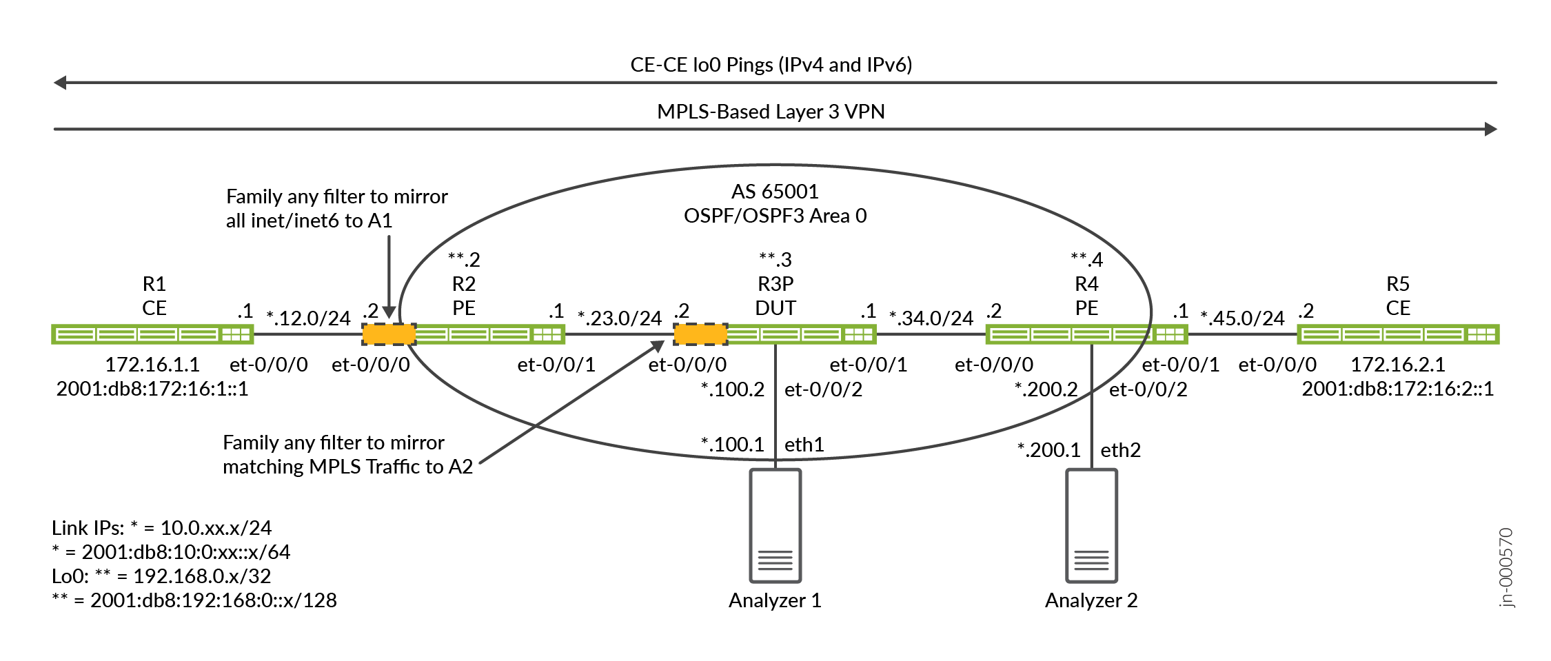
此示例演示了镜像通过提供商网络发送的客户边缘流量的两种方法:
-
第一种方法在 PE-客户边缘 VRF 接口上使用全匹配过滤器。
-
第二种方法演示了应用于提供商 (P) 路由器上的 MPLS 标签匹配过滤器。
PE1 路由器 (R2) 和 P 路由器 (R3) 是配置了远程端口镜像并充当我们的 DUT 的路由器。这些路由器使用家族 any 防火墙过滤器来匹配所选流量,以进行端口镜像。入口过滤器和出口过滤器的组合用于镜像在客户边缘路由器(R1 和 R5)之间流动的请求和响应流量。
远程端口镜像使用隧道进行 GRE 封装,以将镜像流量发送到远程分析器设备。我们的拓扑有两个分析仪。一个连接到 R2/PE1 路由器,另一个连接到 R3/P 路由器。这使我们能够演示两种镜像客户边缘流量的方法,一种在 PE 上,另一种在核心 P 路由器上。我们使用 Centos 主机和 Wireshark 进行数据包捕获和分析。
PTX 平台使用灵活隧道接口 (fti) 基础架构来支持各种隧道应用。对于远程端口镜像,在 FTI 接口上配置 GRE 隧道,以便将镜像流量传输到远程分析器设备。在此示例中,您将配置基于 FTI 的 GRE 隧道、镜像实例和用于选择要镜像的流量的防火墙过滤器。
R2/PE1 配置步骤
有关导航 CLI 的信息,请参阅在 配置模式下使用 CLI 编辑器
有关所有路由器的完整配置,请参阅: 附录 2:在所有路由器上设置命令
本部分重点介绍在此示例中配置 PE1/R2 路由器所需的配置任务。附录中提供了所有路由器的完整配置。步骤 1 总结了示例的基线。此基准包括 IPv4 和 IPv6 连接、MPLS 和第 3 层 VPN。我们的示例将重点放在配置和验证远程端口镜像上。
有关 L3 VPN作和基准配置的详细信息,请参阅 示例:配置基于 MPLS 的基本第 3 层 VPN。
-
在 PE1 路由器上配置 IP 路由和 L3 VPN 基准。这涉及以下内容:
-
为 IPv4 和 IPv6 对接口进行编号,包括
family mpls对面向核心接口的支持。 -
配置 OSPF 和 OSPFv3 路由协议以在所有网络接口之间提供可达性。
-
RSVP 和 MPLS 标签交换路径 (LSP),支持 L3 VPN 流量。
-
使用 PE 路由器的地址族配置
inet-vpnandinet6-vpn[edit] set interfaces et-0/0/0 unit 0 family inet address 10.0.12.2/24 set interfaces et-0/0/0 unit 0 family inet6 address 2001:db8:10:0:12::2/64 set interfaces et-0/0/1 unit 0 family inet address 10.0.23.1/24 set interfaces et-0/0/1 unit 0 family inet6 address 2001:db8:10:0:23::1/64 set interfaces et-0/0/1 unit 0 family mpls set interfaces lo0 unit 0 family inet address 192.168.0.2/32 set interfaces lo0 unit 0 family inet6 address 2001:db8:192:168:0::2/128 set policy-options policy-statement ospf-export term 1 from protocol bgp set policy-options policy-statement ospf-export term 1 then accept set routing-instances ce1 instance-type vrf set routing-instances ce1 protocols ospf area 0.0.0.0 interface all set routing-instances ce1 protocols ospf export ospf-export set routing-instances ce1 protocols ospf3 area 0.0.0.0 interface all set routing-instances ce1 protocols ospf3 export ospf-export set routing-instances ce1 interface et-0/0/0.0 set routing-instances ce1 route-distinguisher 65001:1 set routing-instances ce1 vrf-target target:65001:100 set routing-instances ce1 vrf-table-label set routing-options router-id 192.168.0.2 set routing-options autonomous-system 65001 set protocols bgp group ibgp type internal set protocols bgp group ibgp local-address 192.168.0.2 set protocols bgp group ibgp family inet unicast set protocols bgp group ibgp family inet-vpn unicast set protocols bgp group ibgp family inet6-vpn unicast set protocols bgp group ibgp neighbor 192.168.0.4 set protocols mpls label-switched-path pe2 to 192.168.0.4 set protocols mpls label-switched-path pe2 no-cspf set protocols mpls ipv6-tunneling set protocols mpls interface all set protocols mpls interface fxp0.0 disable set protocols ospf area 0.0.0.0 interface all set protocols ospf area 0.0.0.0 interface fxp0.0 disable set protocols ospf3 area 0.0.0.0 interface all set protocols ospf3 area 0.0.0.0 interface fxp0.0 disable set protocols rsvp interface all set protocols rsvp interface fxp0 disable
介绍了基线之后,剩下的步骤将侧重于配置 R2/PE1 路由器,以端口镜像在其面向 CE1 的 VRF 接口上发送和接收的所有流量。
-
- 首先配置 GRE 隧道。在 PTX 路由器上,隧道通过 FTI 接口实现。GRE隧道的源地址不必是可路由的,除非您希望执行源自GRE隧道源或发往GRE隧道源的诊断ping测试。PE1 镜像的流量的 GRE 目标是分析器 1 路由器。此目标必须可访问,才能将镜像流量发送到分析器。我们使用无源 IGP 实例来确保 IGP 可访问到分析器网络。
目标地址映射到 P/R3 路由器上连接到 et-0/0/2 接口的分析器 1 设备。您必须配置 FTI 逻辑接口,
family ccc以支持 PTX 上的远程端口镜像。这是因为镜像作发生在第 2 层。set interfaces fti0 unit 1 description "GRE tunnel for remote port mirror" set interfaces fti0 unit 1 tunnel encapsulation gre source address 10.100.0.1 set interfaces fti0 unit 1 tunnel encapsulation gre destination address 10.0.100.1 set interfaces fti0 unit 1 family ccc
注意:系统会为连接到分析器的接口调配无源 IGP 实例。这为GRE封装的镜像流量提供了对分析器端口的IGP可访问性。被动设置可防止生成向分析器的hello数据包,因为这只会使捕获变得混乱。
此外,我们在分析器设备上配置了一个静态路由,使其能够响应 ping,以辅助进行诊断测试。严格来说,DUT 和分析器之间只需要单工连接或路由,远程端口镜像即可发挥作用。
- 配置采样实例。我们使用 1 的速率对所有匹配的数据包进行采样。鉴于所有匹配的流量都已采样,默认值
run-length1 将保持不变。您必须在 FTI 路由器上指定用于传输镜像流量的逻辑接口。您在上一步中在 GRE 隧道的 fti0 接口上进行了配置unit 1,以便将同一接口和单元指定为镜像实例中的输出接口。[edit] set forwarding-options port-mirroring instance pe-mirror input rate 1 set forwarding-options port-mirroring instance pe-mirror family any output interface fti0.1
注意:您可以使用该
maximum-packet-length选项在层次结构中[edit forwarding-options port-mirroring instance instance-name input]指定镜像流量的最大数据包长度。默认情况下,数据包长度为 0,这意味着整个数据包都会镜像。 -
定义两个系列
any防火墙过滤器以匹配和镜像客户边缘流量。定义了两个过滤器,一个用于将 CE1 镜像到 CE2 流量,另一个用于将 CE2 镜像到 CE1。过滤器包括一个计数功能以帮助验证。端口镜像作会将匹配流量定向到您之前配置的端口镜像实例。族
any滤波器支持第 2 层和第 3 层匹配。对于前者,您可以根据 VLAN ID、接口、MAC 地址或 MPLS 标签进行匹配。对于后者,您可以在标准 IPv4 或 IPv6 报头字段上进行匹配。鉴于我们的拓扑结构,我们使用“全部匹配”术语来捕获 CE 发送或接收 的所有 流量。这包括 IPv4、IPv6、ARP、LLDP 和任何路由协议,例如 OSPF。
[edit]
set firewall family any filter ce1-ce2 term mirror-ce1-ce2 then count ce1-ce2-mirror
set firewall family any filter ce1-ce2 term mirror-ce1-ce2 then port-mirror-instance pe-mirror
set firewall family any filter ce1-ce2 term mirror-ce1-ce2 then accept
set firewall family any filter ce1-ce2 term else then accept

set firewall family any filter ce2-ce1 term mirror-ce2-ce1 then count ce2-ce1-mirror
set firewall family any filter ce2-ce1 term mirror-ce2-ce1 then port-mirror-instance pe-mirror
set firewall family any filter ce2-ce1 term mirror-ce2-ce1 then accept
set firewall family any filter ce2-ce1 term else then accept
两个过滤器都以匹配全部接受术语结尾,以覆盖 Junos 过滤器末尾的默认拒绝所有作。这样,就可以接受在第一个术语中未匹配的流量。如果稍后将特定匹配条件添加到第一个术语中,则添加此术语作为保护措施。
如果需要,您可以在过滤器中调用监管器作,以限制通过 GRE 隧道发送的镜像数据包数。监管器定义有带宽和突发限制,以及对于超过监管器的流量的丢弃作。
您不能在出口方向上应用带有监管器作的 PM 过滤器。注意:如果只想匹配在客户边缘设备的 IPv4 环路地址之间发送的 ICMP 流量,请将第 3 层匹配标准添加到过滤器中。
set firewall family any filter ce1-ce2 term mirror-ce1-ce2 from ip-version ipv4 ip-protocol icmp
set firewall family any filter ce1-ce2 term mirror-ce1-ce2 from ip-version ipv4 ip-source-address 172.16.1.1/32
set firewall family any filter ce1-ce2 term mirror-ce1-ce2 from ip-version ipv4 ip-destination-address 172.16.2.1/32
set firewall family any filter ce1-ce2 term mirror-ce1-ce2 then count ce1-ce2-mirror
set firewall family any filter ce1-ce2 term mirror-ce1-ce2 then port-mirror-instance pe-mirror
set firewall family any filter ce1-ce2 term mirror-ce1-ce2 then accept
set firewall family any filter ce1-ce2 term else then accept
-
将过滤器应用于 R2/PE1 上面向客户边缘的接口。对于我们的示例,这意味着将过滤器应用于 PE1 上的 et-0/0/0 接口。请注意过滤器应用的方向性。需要入口和出口过滤器来镜像客户边缘流量的两个方向。
[edit]
set interfaces et-0/0/0 unit 0 filter input ce1-ce2
set interfaces et-0/0/0 unit 0 filter output ce2-ce1
为完整起见,我们以大括号格式显示 R2/PE1 的配置。
system {
    host-name r2-ptx;
}
interfaces {
    et-0/0/0 {
        unit 0 {
            filter {
                input ce1-ce2;
                output ce2-ce1;
            }
            family inet {
                address 10.0.12.2/24;
            }
            family inet6 {
                address 2001:db8:10:0:12::2/64;
            }
        }
    }
    et-0/0/1 {
        unit 0 {
            family inet {
                address 10.0.23.1/24;
            }
            family inet6 {
                address 2001:db8:10:0:23::1/64;
            }
            family mpls;
        }
    }
    fti0 {
        unit 1 {
            description "GRE tunnel for remote port mirror";
            tunnel {
                encapsulation gre {
                    source {
                        address 10.100.0.1;
                    }
                    destination {
                        address 10.0.100.1;
                    }
                }
            }
            family ccc;
        }
    }
    lo0 {
        unit 0 {
            family inet {
                address 192.168.0.2/32;
            }
            family inet6 {
                address 2001:db8:192:168:0::2/128;
            }
        }
    }
}
forwarding-options {
    port-mirroring {
        instance {
            pe-mirror {
                input {
                    rate 1;
                }
                family any {
                    output {
                        interface fti0.1;
                    }
                }
            }
        }
    }
}
policy-options {
    policy-statement ospf-export {
        term 1 {
            from protocol bgp;
            then accept;
        }
    }
}
firewall {
    family any {
        filter ce1-ce2 {
            term mirror-ce1-ce2 {
                then {
                    count ce1-ce2-mirror;
                    port-mirror-instance pe-mirror;
                    accept;
                }
            }
        }
        filter ce2-ce1 {
            term mirror-ce2-ce1 {
                then {
                    count ce2-ce1-mirror;
                    port-mirror-instance pe-mirror;
                    accept;
                }
            }
        }
    }
}
routing-instances {
    ce1 {
        instance-type vrf;
        protocols {
            ospf {
                area 0.0.0.0 {
                    interface all;
                }
                export ospf-export;
            }
            ospf3 {
                area 0.0.0.0 {
                    interface all;
                }
                export ospf-export;
            }
        }
        interface et-0/0/0.0;
        route-distinguisher 65001:1;
        vrf-target target:65001:100;
        vrf-table-label;
    }
}
routing-options {
    router-id 192.168.0.2;
    autonomous-system 65001;
}
protocols {
    bgp {
        group ibgp {
            type internal;
            local-address 192.168.0.2;
            family inet {
                unicast;
            }
            family inet-vpn {
                unicast;
            }
            family inet6-vpn {
                unicast;
            }
            neighbor 192.168.0.4;
        }
    }
    mpls {
        label-switched-path pe2 {
            to 192.168.0.4;
            no-cspf;
        }
        ipv6-tunneling;
        interface all;
        interface fxp0.0 {
            disable;
        }
    }
    ospf {
        area 0.0.0.0 {
            interface all;
            interface fxp0.0 {
                disable;
            }
        }
    }

    ospf3 {
        area 0.0.0.0 {
            interface all;
            interface fxp0.0 {
                disable;
            }
            interface et-0/0/2.0 {
                passive;
            }
        }
    }
    rsvp {
        interface all;
    }
}
R3 配置步骤
有关导航 CLI 的信息,请参阅在 配置模式下使用 CLI 编辑器
有关所有路由器的完整配置,请参阅: 附录 2:在所有路由器上设置命令
本节重点介绍在此示例中配置 P/R3 路由器所需的主要配置任务。我们从基于 MPLS 的 L3 VPN 基准开始。然后,我们将展示在 P 路由器上配置远程端口镜像以匹配和镜像 MPLS 流量所需的步骤。
-
在 P/R3 路由器上配置 IPv4 和 IPv6 路由以及 MPLS 基准。这涉及几个方面:
-
为 IPv4 和 IPv6 对接口进行编号,包括
family mpls对面向核心接口的支持。 -
配置 OSPF 和 OSPFv3 路由协议,以便在所有网络接口之间提供可达性。
-
RSVP 和 MPLS 来支持 L3 VPN 数据平面。作为 P 路由器,不存在 BGP 对等和 VRF 定义。
[edit]
set interfaces et-0/0/0 description "R3-R2 P-PE"
set interfaces et-0/0/0 unit 0 family inet address 10.0.23.2/24
set interfaces et-0/0/0 unit 0 family inet6 address 2001:db8:10:0:23::2/64
set interfaces et-0/0/0 unit 0 family mpls
set interfaces et-0/0/1 unit 0 family inet address 10.0.34.1/24
set interfaces et-0/0/1 unit 0 family inet6 address 2001:db8:10:0:34::1/64
set interfaces et-0/0/1 unit 0 family mpls
set interfaces et-0/0/2 unit 0 family inet address 10.0.100.2/24
set interfaces lo0 unit 0 family inet address 192.168.0.3/32
set interfaces lo0 unit 0 family inet6 address 2001:db8:192:168:0::3/128

set routing-options router-id 192.168.0.3

set protocols mpls interface all
set protocols mpls interface fxp0.0 disable
set protocols mpls interface et-0/0/2.0 disable

set protocols ospf area 0.0.0.0 interface all
set protocols ospf area 0.0.0.0 interface fxp0.0 disable
set protocols ospf area 0.0.0.0 interface et-0/0/2.0 passive

set protocols ospf3 area 0.0.0.0 interface all
set protocols ospf3 area 0.0.0.0 interface fxp0.0 disable
set protocols ospf3 area 0.0.0.0 interface et-0/0/2.0 passive

set protocols rsvp interface all
set protocols rsvp interface fxp0 disable
set protocols rsvp interface et-0/02.0 disable
P1/R3 路由器通过 et-0/0/2 接口连接到分析器 1。当镜像流量使用 GRE 封装以 IPv4 的形式到达时,我们将在此接口上禁用 RSVP 协议和 MPLS 支持。LSP 不会扩展到分析器。
注意:此处使用的 et-0/0/2 接口配置假定分析器会回复 DUT 发送的 ARP 和 ND 请求,以便进行 MAC 地址解析。如果不是这种情况,或者您希望 ARP 流量不属于数据包捕获的一部分,则应配置静态 ARP 条目。请务必为连接到 DUT 的分析器设备上的接口指定正确的 MAC 地址。
了解基线后,以下步骤重点介绍为 P 路由器上的 MPLS 流量配置远程端口镜像。
-
- 您从定义 GRE 隧道开始。在 PTX 平台上,隧道是在 FTI 接口上实施的。GRE隧道的源地址不必是可路由的,除非您希望执行源自GRE隧道源或发往GRE隧道源的诊断ping测试。镜像流量的 GRE 目的是连接到 PE2/R4 的分析器 2 设备。此目标必须可访问,才能将镜像流量发送到分析器。我们使用无源 IGP 实例来确保 IGP 可访问到分析器网络。
您必须配置 FTI 逻辑接口,
family ccc以支持 PTX 上的远程端口镜像。这是因为镜像作发生在第 2 层。[edit] set interfaces fti0 unit 1 tunnel encapsulation gre source address 10.100.0.3 set interfaces fti0 unit 1 tunnel encapsulation gre destination address 10.0.200.1 set interfaces fti0 unit 1 family ccc
注意:系统会为连接到分析器的接口调配无源 IGP 实例。这为GRE封装的镜像流量提供了对分析器端口的IGP可访问性。被动设置可防止生成向分析器的 hello 数据包,因为这只会使数据包捕获变得混乱。
此外,我们在分析器设备上配置了一个静态路由,以便它可以响应 ping,以帮助进行诊断测试。严格来说,DUT 和分析器之间只需要单工连接或路由,远程端口镜像即可发挥作用。
- 配置采样实例。我们使用 1 的速率来选择并采样所有匹配的数据包。默认情况下,为
run-length1。鉴于所有匹配流量都以 1 的速率进行采样,这很好。您必须在 FTI 路由器上指定用于发送镜像流量的逻辑接口。您在上一步中为 fti 接口配置了单元 1,以便将同一单元指定为镜像实例的输出接口。[edit] set forwarding-options port-mirroring instance p-router-mirror input rate 1 set forwarding-options port-mirroring instance p-router-mirror family any output interface fti0.1
-
定义防火墙过滤器以镜像在客户边缘路由器之间传输的流量。
族
any过滤器仅允许第 2 层匹配类型。例如,VLAN ID、接口、MAC 地址或 MPLS 标签。因此,您无法使用 IPv4 或 IPv4 特定的匹配条件。定义了两个过滤器,CE 之间的每个流量流向一个。
鉴于我们在 P 路由器上镜像 VPN 流量,因此编写过滤器的目的是与标识两个 PE 路由器之间的 MPLS 流量流的特定标签进行匹配。
对于 CE1 到 CE2 方向,过滤器与 PE1 用于到达 PE2 的 RSVP 传输标签匹配。由于 PHP 和出口应用程序的原因,CE2 到 CE1 方向中使用的过滤器与 PE1 到 PE2 播发的 VRF 标签上匹配。匹配流量会将端口镜像作唤起到之前定义的镜像实例。过滤器包括计数功能,以帮助确认正确作。
我们使用以下命令确定了正确的标签:
-
对于 CE1 向 CE2 发送的流量,将通过命令
show rsvp session ingress detail显示当前 RSVP 传输标签。这是 PE1 使用 MPLS 到达 PE2 的 RSVP 分配标签。应注意的是,此 PE 对之间发送的所有 VPN 流量都使用相同的 RSVP 传输。生成的过滤器并不特定于 PE 路由器上的 CE1 VRF。user@r2-ptx> show rsvp session ingress detail Ingress RSVP: 1 sessions 192.168.0.4 From: 192.168.0.2, LSPstate: Up, ActiveRoute: 0 LSPname: pe2, LSPpath: Primary LSPtype: Static Configured Suggested label received: -, Suggested label sent: - Recovery label received: -, Recovery label sent: 22 Resv style: 1 FF, Label in: -, Label out: 22 Time left: -, Since: Tue Apr 18 12:58:47 2023 Tspec: rate 0bps size 0bps peak Infbps m 20 M 1500 Port number: sender 2 receiver 65196 protocol 0 PATH rcvfrom: localclient Adspec: sent MTU 1500 Path MTU: received 1500 PATH sentto: 10.0.23.2 (et-0/0/1.0) 1 pkts RESV rcvfrom: 10.0.23.2 (et-0/0/1.0) 1 pkts, Entropy label: Yes Record route: <self> 10.0.23.2 10.0.34.2 Total 1 displayed, Up 1, Down 0
在这种情况下,输出显示 RSVP 标签 22 已分配给 PE1/R2 路由器,以到达 PE2/R4 路由器的 LSP 出口。
-
对于由 CE2 发送到 CE1 的流量,必须在 VRF 标签上匹配。这是因为 P 路由器是倒数第二个跃点节点,在出口接口上,它会弹出 RSVP 传输标签。这会在 VRF 标签上作为堆栈的底部。您可使用
show route advertising-protocol bgp remote-peer-address detail命令确认 PE1 向 PE2 播发的 VRF 标签。此命令显示本地 PE 播发的路由以及绑定到路由实例的 VRF 标签。user@r2-ptx> show route advertising-protocol bgp 192.168.0.4 detail ce1.inet.0: 7 destinations, 8 routes (7 active, 0 holddown, 0 hidden) * 10.0.12.0/24 (1 entry, 1 announced) BGP group ibgp type Internal Route Distinguisher: 65001:1 VPN Label: 16 Nexthop: Self Flags: Nexthop Change Localpref: 100 AS path: [65001] I Communities: target:65001:100 * 172.16.1.1/32 (1 entry, 1 announced) BGP group ibgp type Internal Route Distinguisher: 65001:1 VPN Label: 16 Nexthop: Self Flags: Nexthop Change MED: 1 Localpref: 100 AS path: [65001] I Communities: target:65001:100 rte-type:0.0.0.0:1:0 . . .输出显示,PE1 向 PE2 路由器发出了与 CE1 路由实例关联的路由的 VRF 标签 16 信号。
根据前面命令中的信息,我们知道要在防火墙过滤器中匹配哪些 RSVP/VRF 标签。
[edit]
set firewall family any filter ce1-ce2 term ce1-ce2-mirror from mpls-label 22
set firewall family any filter ce1-ce2 term ce1-ce2-mirror then count ce1-ce2-traffic
set firewall family any filter ce1-ce2 term ce1-ce2-mirror then port-mirror-instance p-router-mirror
set firewall family any filter ce1-ce2 term else then accept

set firewall family any filter ce2-ce1 term ce2-ce1-mirror from mpls-label 16
set firewall family any filter ce2-ce1 term ce2-ce1-mirror then count ce2-ce1-traffic
set firewall family any filter ce2-ce1 term ce2-ce1-mirror then port-mirror-instance p-router-mirror
set firewall family any filter ce2-ce1 term else then accept
过滤器以匹配全部接受条款结尾,以覆盖 Junos 过滤器末尾的默认拒绝全部。这样,就可以接受在第一个术语中未匹配的流量。这对于避免中断使用此接口的所有其他流量至关重要!
注意:由于链路中断或其他配置更改引起的 LSP 重新信号,RSVP 标签可能会发生变化。我们演示了如何使用过滤器来匹配特定标签,以帮助限制镜像流量。您始终可以应用全部匹配过滤器,以确保 MPLS 标签更改不会影响镜像。全部匹配方法的缺点是,您将镜像 P 路由器接口上接收的所有流量,以包括核心协议和非 VPN 流量。
-
-
将过滤器应用于 P/R3 路由器上面向 PE1 的接口。过滤器应用的方向性很重要。我们的滤波器设计用于在 CE1 到 CE2 流量的输入方向上运行,在 CE2 到 CE1 流量的出口方向上运行。由于这些是系列 Any 过滤器,因此它们在单元级别应用,与 IPv4 或 IPv6 无关。系列 任何过滤器都可以在独立于任何协议家族的第 2 层运行。
[edit]
set interfaces et-0/0/0 unit 0 filter input ce1-ce2
set interfaces et-0/0/0 unit 0 filter output ce2-ce1
为完整起见,我们以大括号格式显示 R2/PE1 的配置。
system {
    host-name r3-ptx;
}
interfaces {
    et-0/0/0 {
        description "R3-R2 P-PE";
        unit 0 {
            filter {
                input ce1-ce2;
                output ce2-ce1;
            }
            family inet {
                address 10.0.23.2/24;
            }
            family inet6 {
                address 2001:db8:10:0:23::2/64;
            }
            family mpls;
        }
    }
    et-0/0/1 {
        unit 0 {
            family inet {
                address 10.0.34.1/24;
            }
            family inet6 {
                address 2001:db8:10:0:34::1/64;
            }
            family mpls;
        }
    }
    et-0/0/2 {
        unit 0 {
            family inet {
                address 10.0.100.2/24;
            }
        }
    }
    fti0 {
        unit 1 {
            tunnel {
                encapsulation gre {
                    source {
                        address 10.100.0.3;
                    }
                    destination {
                        address 10.0.200.1;
                    }
                }
            }
            family ccc;
        }
    }
    lo0 {
        unit 0 {
            family inet {
                address 192.168.0.3/32;
            }
            family inet6 {
                address 2001:db8:192:168:0::3/128;
            }
        }
    }
}
forwarding-options {
    port-mirroring {
        instance {
            p-router-mirror {
                input {
                    rate 1;
                }
                family any {
                    output {
                        interface fti0.1;
                    }
                }
            }
        }
    }
}
firewall {
    family any {
        filter ce1-ce2 {
            term ce1-ce2-mirror {
                from {
                    mpls-label 22;
                }
                then {
                    count ce1-ce2-traffic;
                    port-mirror-instance p-router-mirror;
                }
            }
            term else {
                then accept;
            }
        }
        filter ce2-ce1 {
            term ce2-ce1-mirror {
                from {
                    mpls-label 16;
                }
                then {
                    count ce2-ce1-traffic;
                    port-mirror-instance p-router-mirror;
                }
            }
            term else {
                then accept;
            }
        }
    }
}
routing-options {
    router-id 192.168.0.3;
}
protocols {
    mpls {
        interface all;
        interface fxp0.0 {
            disable;
        }
        interface et-0/0/2.0 {
            disable;
        }
    }
    ospf {
        area 0.0.0.0 {
            interface all;
            interface fxp0.0 {
                disable;
            }
            interface et-0/0/2.0 {
                passive;
            }
        }
    }
    ospf3 {
        area 0.0.0.0 {
            interface all;
            interface fxp0.0 {
                disable;
            }
            interface et-0/0/2.0 {
                passive;
            }
        }
    }
    rsvp {
        interface all;
        interface et-0/0/2.0 {
            disable;
        }
    }
}
验证
在此示例中,有两个配置了端口镜像的 DUT。验证机制是相同的。在这两种情况下,您都需要确认过滤器与预期流量匹配,并且镜像数据包已发送到关联的分析器。
通过我们的配置,PE 镜像流量被发送到分析器 1,而 P 路由器镜像流量被发送到分析器 2。如果需要,所有镜像流量都可以发送到同一目标,但是,如果端口镜像同时在多个位置发生,这会导致流量穿插。
根据需要,可以在其中一个或两个 DUT 路由器上执行这些步骤。R2/PE1 是第一个 DUT,P 路由器/R3 是第二个 DUT。
-
确认 OSPF 和 OSPF3 邻接方和路由到所有环路地址。此外,验证到远程分析器 IP 地址的路由。您必须能够将 IPv4 数据包发送到远程分析器。或者,分析器可以配置静态路由,以便它可以回复。
user@r2-ptx> show ospf neighbor

Address          Interface              State           ID               Pri  Dead
10.0.23.2        et-0/0/1.0             Full            192.168.0.3      128    36

user@r2-ptx> show ospf3 neighbor

ID               Interface              State     Pri   Dead
192.168.0.3      et-0/0/1.0             Full      128     36
  Neighbor-address fe80::569e:18ff:fe45:ffff


user@r2-ptx> show route protocol ospf | match /32
192.168.0.3/32     *[OSPF/10] 2d 22:41:49, metric 1
192.168.0.4/32     *[OSPF/10] 2d 22:41:49, metric 2
224.0.0.5/32       *[OSPF/10] 2d 22:43:37, metric 1
172.16.1.1/32      *[OSPF/10] 2d 22:41:45, metric 1
224.0.0.5/32       *[OSPF/10] 2d 22:43:37, metric 1

user@r2-ptx> show route protocol ospf3 | match /128
2001:db8:192:168::3/128
2001:db8:192:168::4/128
ff02::5/128        *[OSPF3/10] 2d 22:47:10, metric 1
2001:db8:172:16:1::1/128
ff02::5/128        *[OSPF3/10] 2d 21:38:06, metric 1
注意:在上述输出中,172.16.1.1/32路由是在路由实例中
ce1获知的。因此,使用此命令,您已确认核心和客户边缘中的 OSPF作正确!仅列出本地 CE1 环路,因为远程客户边缘环路作为 BGP 路由学习。在连接到分析仪的接口上配置的无源 IGP 实例提供了所需的 IP 连接。同样,我们向分析器添加静态路由,以允许返回流量进行诊断测试。
user@r2-ptx> show route 10.0.100.1 inet.0: 15 destinations, 15 routes (15 active, 0 holddown, 0 hidden) + = Active Route, - = Last Active, * = Both 10.0.100.0/24 *[OSPF/10] 2d 22:49:10, metric 2 > to 10.0.23.2 via et-0/0/1.0 user@r2-ptx> show route 10.0.200.1 inet.0: 15 destinations, 15 routes (15 active, 0 holddown, 0 hidden) + = Active Route, - = Last Active, * = Both 10.0.200.0/24 *[OSPF/10] 1d 20:36:13, metric 3 > to 10.0.23.2 via et-0/0/1.0 user@r2-ptx> ping 10.0.100.1 count 2 PING 10.0.100.1 (10.0.100.1) 56(84) bytes of data. 64 bytes from 10.0.100.1: icmp_seq=1 ttl=63 time=5.48 ms 64 bytes from 10.0.100.1: icmp_seq=2 ttl=63 time=4.91 ms --- 10.0.100.1 ping statistics --- 2 packets transmitted, 2 received, 0% packet loss, time 1002ms rtt min/avg/max/mdev = 4.908/5.196/5.484/0.288 ms -
确认 FTI 接口和 GRE 隧道状态。
user@r2-ptx> show interfaces fti0.1 detail
  Logical interface fti0.1 (Index 1000) (SNMP ifIndex 543) (Generation 609885357005)
    Description: GRE tunnel for remote port mirror
    Flags: Up Point-To-Point Encapsulation: GRE DF
          , Source address: 10.100.0.1/32, Destination address: 10.0.100.1
  Traffic statistics:
   Input  bytes  :                    0
   Output bytes  :             12887342
   Input  packets:                    0
   Output packets:                99020
    Local statistics:
     Input  bytes  :                    0
     Output bytes  :                    0
     Input  packets:                    0
     Output packets:                    0
    Transit statistics:
     Input  bytes  :                    0                    0 bps
     Output bytes  :             12887342                    0 bps
     Input  packets:                    0                    0 pps
     Output packets:                99020                    0 pps
    Protocol ccc, MTU: 1476, Generation: 609885357006, Route table: 0
      Flags: Is-Primary
输出中的突出显示表示隧道接口和 GRE 隧道已正常运行。非 0 输出数据包计数器表示流量正在镜像。我们不需要任何输入数据包,因为此 GRE 隧道仅用于将镜像流量发送到远程分析器。
-
确认端口镜像实例。端口镜像状态应为
up,并且目标下方应列出正确的镜像接口。该系列any指示为与协议家族无关的第 2 层端口镜像实例。镜像流量包括原始第 2 层帧及其内容。user@r2-ptx> show forwarding-options port-mirroring Instance Name: pe-mirror Instance Id: 1 Input parameters: Rate : 1 Run-length : 1 Maximum-packet-length : 0 Output parameters: Family State Destination Next-hop any up fti0.1 NA -
清除 DUT 上的防火墙计数器和接口统计信息。然后,在客户边缘路由器环路地址之间生成已知数量的 IPv4 和 IPv6 测试数据包。
user@r2-ptx> clear firewall all
user@r2-ptx> clear interfaces statistics all
user@r1-ptx> ping 172.16.2.1 source 172.16.1.1 count 4
PING 172.16.2.1 (172.16.2.1) from 172.16.1.1 : 56(84) bytes of data.
64 bytes from 172.16.2.1: icmp_seq=1 ttl=61 time=1237 ms
64 bytes from 172.16.2.1: icmp_seq=2 ttl=61 time=178 ms
64 bytes from 172.16.2.1: icmp_seq=3 ttl=61 time=507 ms
64 bytes from 172.16.2.1: icmp_seq=4 ttl=61 time=417 ms

--- 172.16.2.1 ping statistics ---
4 packets transmitted, 4 received, 0% packet loss, time 3066ms
rtt min/avg/max/mdev = 177.830/584.676/1237.435/395.575 ms, pipe 2

user@r1-ptx> ping 2001:db8:172:16:2::1 source 2001:db8:172:16:1::1 count 4
64 bytes from 2001:db8:172:16:2::1: icmp_seq=1 ttl=62 time=978 ms
64 bytes from 2001:db8:172:16:2::1: icmp_seq=2 ttl=62 time=621 ms
64 bytes from 2001:db8:172:16:2::1: icmp_seq=3 ttl=62 time=782 ms
64 bytes from 2001:db8:172:16:2::1: icmp_seq=4 ttl=62 time=920 ms

--- 2001:db8:172:16:2::1 ping statistics ---
4 packets transmitted, 4 received, 0% packet loss, time 2999ms
rtt min/avg/max/mdev = 621.122/825.114/978.021/137.715 ms
-
返回 R2/PE1,显示防火墙计数器和接口统计信息,以确认其反映了测试流量。您可能会看到,在 CE1 到 客户边缘 2 方向上计算了一些额外的数据包,这些数据包反映了 CE12 和 PE1 路由器之间的 OSPF、OSPF3 或 ARP 交换。请注意,在 CE12 到 CE1 方向上,出口方向上的过滤器应用仅捕获端到端流量。因此,CE2-CE1 计数器确实反映了生成的测试流量。
user@r2-ptx> show firewall

Filter: ce1-ce2
Counters:
Name                                                                            Bytes              Packets
ce1-ce2-mirror                                                                   1353                   13

Filter: ce2-ce1
Counters:
Name                                                                            Bytes              Packets
ce2-ce1-mirror                                                                   752                    8
显示用于将流量镜像到远程分析器的 fti0./1 接口的接口统计信息。
user@r3-ptx> show interfaces fti0.1 detail
  Logical interface fti0.1 (Index 1000) (SNMP ifIndex 543) (Generation 609885357005)
    Description: GRE tunnel for remote port mirror
    Flags: Up Point-To-Point Encapsulation: GRE DF
          , Source address: 10.100.0.1/32, Destination address: 10.0.100.1
  Traffic statistics:
   Input  bytes  :                    0
   Output bytes  :                 2424
   Input  packets:                    0
   Output packets:                   20
    Local statistics:
     Input  bytes  :                    0
     Output bytes  :                    0
     Input  packets:                    0
     Output packets:                    0
    Transit statistics:
     Input  bytes  :                    0                    0 bps
     Output bytes  :                 2424                 2096 bps
     Input  packets:                    0                    0 pps
     Output packets:                   20                    2 pps
    Protocol ccc, MTU: 1476, Generation: 609885357006, Route table: 0
      Flags: Is-Primary
生成了 8 个测试数据包后,您可能会惊讶地发现 fti0.1 接口出口上的数据包计数为 20。首先,回想一下,CE1 路由器发送的 OSPF 和 OSPF3 hellos 数据包正在镜像中。其次,考虑到 ping 请求和回复都在 PE1/R2 上镜像。这意味着总共有 8 个 ping 请求和 8 个回复,总共有 16 个 ICMP 测试数据包。
-
在监控站上运行 tcpdump 或您选择的分析应用程序,以确认镜像测试流量的接收和处理。我们的设置有两个分析仪设备,或者准确地说,是一个具有两个接口的分析仪主机。如果需要,可以同时在两个分析器接口上执行此步骤。回想一下,镜像到分析器 2 上的 eth2 接口的流量会镜像到 P 路由器/R3,因此包含 MPLS 封装。从 R1/PE1 镜像的流量不包含 MPLS 封装。
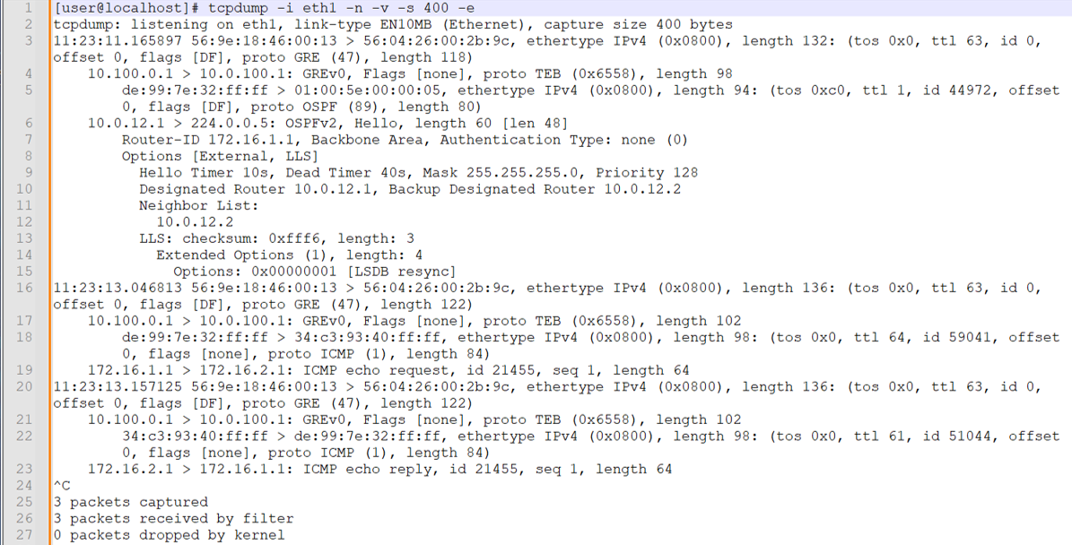
我们首先对从 R2/PE1 接收镜像流量的 eth1 接口进行捕获。开始捕获后,我们将在客户边缘路由器之间执行一次 IPv4 ping。
注意:捕获后,我们将基于文本的 tcpdump 输出粘贴到显示行号的文本应用程序中。这使得调用捕获的关键部分变得更加容易。我们还启用了换行功能来提高可见性。
捕获中需要注意的方面包括:
-
我们在 eth1 接口上调用 tcpdump,并包含用于阻止名称解析、提供详细信息、捕获多达 400 字节以及包含第 2 层标头的标志。
-
第 3 行是第一个第 2 层帧和 IP 数据包的起点。以太网帧是 R3/P1 路由器用来将流量发送到本地连接的分析器设备的封装。目标 MAC 地址由分析器 1 上的 eth1 接口所有。100.0.100.1 IP 到 MAC 地址解析通过 ARP 执行。以太网帧表示它携带 IP 协议。在 IP 层,我们看到数据包设置了“不分段”位,并标识有效负载为 GRE。
-
第 4 行显示外部 IP 数据包及其 GRE 有效负载的解码。源和目标 IP 地址反映了在 R2/PE1 的 fti0.1 接口上配置的 GRE 隧道。GRE 报头通过透明以太网桥接 (TEB) 协议 ID 标识其有效负载为第 2 层帧。这证实了在使用家族
any过滤器的 PTX 平台上进行远程端口镜像会导致第 2 层帧的镜像。 -
第 5 行是 GRE 数据包有效负载的解码。源和目标 MAC 地址(分别为 de:99:7e:32:ff:ff 和 01:00:5e:00:00:05)反映了用于在链路层进行 OSPF hello 组播的地址。第 5 行还显示 GRE 封装第 2 层帧的有效负载为 IP,IP 数据包的有效负载为 OSPF。
注意:客户边缘与 PE 之间的 OSPF hello 交换在第 3 层 VPN 中是本地的。我们看到本地客户边缘发送的 OSPF 数据包,因为入口处的端口镜像作捕获了所有流量。远程客户边缘生成的 OSPF hello 数据包不会通过核心传输,因此在捕获中不会被视为出口。
-
第 6 行解码 CE1 路由器发送的 OSPF hello。源 IP 地址将分配给 CE1 的 et-0/0/0.0 接口。目标 IP 地址用于 OSPF 组播。
-
我们跳过 OSPF 解码并降落在第 16 行。这是捕获中的第二帧,反映 IPv4 ICMP 回显请求。第 2 层帧同样反映 P1/R3 和分析器 1 设备的 MAC 地址。我们看到外帧携带一个带有 GRE 有效负载的 IP 数据包。外部 IP 数据包的源和目标 IP 地址反映了在 R2/PE2 上配置的 GRE 隧道。
-
第 18 行开始解码 GRE 有效负载。我们再次看到 CE1 和 PE1 路由器的 MAC 地址。在 IP 层,我们看到数据包是从 CE1 路由器的环路地址发送的。目标 IP 是 CE2 的环路地址。内部 IP 数据包的有效负载是从 CE1 发送到 CE2 的 ICMP 回显请求。
-
第 20 行解码 CE2 发送的 ICMP 回显回复。这可以确认端口镜像在 CE1 传输和接收方向上都正常工作。
-
接下来,我们在 Analyzer 2 的 eth2 接口上进行捕获时,在客户边缘路由器之间生成单个 IPv6 ping。这可以确认 R3/P 路由器上的端口镜像配置以及 IPv6 端口镜像支持。
注意:捕获后,我们将基于文本的 tcpdump 输出粘贴到显示行号的文本应用程序中。这使得调用捕获的关键部分变得更加容易。我们还启用了换行功能来提高可见性。
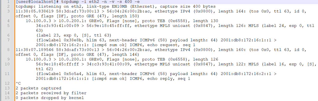
请注意,会同时显示请求和响应流量。鉴于此端口镜像发生在 P 路由器上,客户边缘路由器之间的 OSPF 数据包不会镜像,因为它们不会通过提供商核心发送。此捕获需要注意的事项包括:
-
在第 3 行,对外部以太网帧进行解码。源和目标 MAC 地址现在分别反映 R4/PE2 和分析器设备。
-
在第 4 行,内部 IP 数据包被解码。帧指示 GRE 封装,源 IP 和目标 IP 确认此流量已通过 R3/P1 路由器上配置的 fti0.1 GRE 隧道进行镜像。GRE 封装显示 TEB 协议,表示已封装第 2 层以太网帧。
-
第 5 行开始对内部以太网帧及其 MPLS 有效负载进行解码。源 MAC 地址将分配给 R2/PE1 路由器上的 et-0/0/1 接口。目标 MAC 与 R3/P1 路由器上的 et-0/0/0 接口相关联。
内部以太网帧标识 MPLS 的有效负载。这与在 MPLS 标签上的过滤器项匹配的 P 路由器上执行的第 2 层端口镜像一致。
请注意,在 CE1 到 CE2 方向上,镜像流量会显示两个 MPLS 标签。RSVP 传输标签为 24(这可能会由于 LSP 重新信令而更改),内部 VRF 标签设置为 23,这是与 R2/PE1 路由器上的 CE1 路由实例关联的 VRF 标签。
注意:捕获时,PE1 用来到达 PE2 的 MPLS 传输标签已更改。我们更新了 R3/P1 处的过滤器定义,以反映本节中捕获的当前 RSVP 传输标签值 24。
-
第 7 行解码 MPLS 帧的 IPv6 有效负载。这是 CE1 向 CE2 发送的 IPv6 数据包。IPv6 数据包将其有效负载标识为 ICMP6,并表明这是一个回显请求。
-
第 8 行开始解码来自 CE2 的回复流量。在 CE2 到 CE1 的方向上,镜像流量中仅存在一个标签。这是 R3/PE1 路由器在将流量发送到 R2/PE1 路由器之前执行倒数第二个跃点弹出 (PHP) 后保留的 VRF 标签。在 P1 到 PE2 方向的出口处镜像的流量。
在两个分析器设备上的捕获都确认远程端口镜像正在按预期工作。
-
-
最后,我们将对分析器 2 设备上捕获的相同客户边缘到客户边缘测试流量进行 GUI 解码。再次请注意,在基于 MPLS 的 PE 路由器上,存在反映端口镜像作的 MPLS 标签。
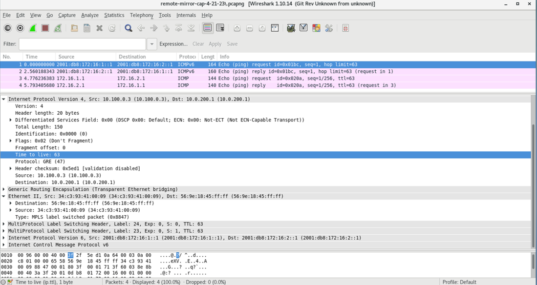 捕获显示正在镜像的 IPv4 和 IPv6 测试流量。此捕获反映了由 P 路由器镜像的流量。因此,存在 MPLS 封装。
附录:在所有路由器上设置命令
要快速配置此示例,请复制以下命令,将其粘贴到文本文件中,移除所有换行符,更改任何必要的详细信息以匹配您的网络配置,然后将命令复制粘贴到 [edit] 层级的 CLI 中。
R1 (CE1)
del interfaces et-0/0/0
set interfaces et-0/0/0 unit 0 family inet address 10.0.12.1/24
set interfaces et-0/0/0 unit 0 family inet6 address 2001:db8:10:0:12::1/64
set interfaces lo0 unit 0 family inet address 172.16.1.1/32
set interfaces lo0 unit 0 family inet6 address 2001:db8:172:16:1::1/128
set routing-options router-id 172.16.1.1
set protocols ospf area 0.0.0.0 interface all
set protocols ospf area 0.0.0.0 interface fxp0.0 disable
set protocols ospf3 area 0.0.0.0 interface all
set protocols ospf3 area 0.0.0.0 interface fxp0.0 disable
R2 (PE1) DUT1
set interfaces et-0/0/0 unit 0 filter input ce1-ce2
set interfaces et-0/0/0 unit 0 filter output ce2-ce1
set interfaces et-0/0/0 unit 0 family inet address 10.0.12.2/24
set interfaces et-0/0/0 unit 0 family inet6 address 2001:db8:10:0:12::2/64
set interfaces et-0/0/1 unit 0 family inet address 10.0.23.1/24
set interfaces et-0/0/1 unit 0 family inet6 address 2001:db8:10:0:23::1/64
set interfaces et-0/0/1 unit 0 family mpls
set interfaces fti0 unit 1 description "GRE tunnel for remote port mirror"
set interfaces fti0 unit 1 tunnel encapsulation gre source address 10.100.0.1
set interfaces fti0 unit 1 tunnel encapsulation gre destination address 10.0.100.1
set interfaces fti0 unit 1 family ccc
set interfaces lo0 unit 0 family inet address 192.168.0.2/32
set interfaces lo0 unit 0 family inet6 address 2001:db8:192:168:0::2/128
set forwarding-options port-mirroring instance pe-mirror input rate 1
set forwarding-options port-mirroring instance pe-mirror input run-length 1
set forwarding-options port-mirroring instance pe-mirror family any output interface fti0.1
set policy-options policy-statement ospf-export term 1 from protocol bgp
set policy-options policy-statement ospf-export term 1 then accept
set firewall family any filter ce1-ce2 term mirror-ce1-ce2 then count ce1-ce2-mirror
set firewall family any filter ce1-ce2 term mirror-ce1-ce2 then port-mirror-instance pe-mirror
set firewall family any filter ce1-ce2 term mirror-ce1-ce2 then accept
set firewall family any filter ce2-ce1 term mirror-ce2-ce1 then count ce2-ce1-mirror
set firewall family any filter ce2-ce1 term mirror-ce2-ce1 then port-mirror-instance pe-mirror
set firewall family any filter ce2-ce1 term mirror-ce2-ce1 then accept
set routing-instances ce1 instance-type vrf
set routing-instances ce1 protocols ospf area 0.0.0.0 interface all
set routing-instances ce1 protocols ospf export ospf-export
set routing-instances ce1 protocols ospf3 area 0.0.0.0 interface all
set routing-instances ce1 protocols ospf3 export ospf-export
set routing-instances ce1 interface et-0/0/0.0
set routing-instances ce1 route-distinguisher 65001:1
set routing-instances ce1 vrf-target target:65001:100
set routing-instances ce1 vrf-table-label
set routing-options router-id 192.168.0.2
set routing-options autonomous-system 65001
set protocols bgp group ibgp type internal
set protocols bgp group ibgp local-address 192.168.0.2
set protocols bgp group ibgp family inet unicast
set protocols bgp group ibgp family inet-vpn unicast
set protocols bgp group ibgp family inet6-vpn unicast
set protocols bgp group ibgp neighbor 192.168.0.4
set protocols mpls label-switched-path pe2 to 192.168.0.4
set protocols mpls label-switched-path pe2 no-cspf
set protocols mpls interface all
set protocols mpls interface fxp0.0 disable
set protocols ospf area 0.0.0.0 interface all
set protocols ospf area 0.0.0.0 interface fxp0.0 disable
set protocols ospf3 area 0.0.0.0 interface all
set protocols ospf3 area 0.0.0.0 interface fxp0.0 disable
set protocols ospf3 area 0.0.0.0 interface et-0/0/2.0 passive
set protocols rsvp interface all
set protocols rsvp interface fxp0 disable
R3(P 路由器)DUT 2
set interfaces et-0/0/0 description "R3-R2 P-PE"
set interfaces et-0/0/0 unit 0 filter input ce1-ce2
set interfaces et-0/0/0 unit 0 filter output ce2-ce1
set interfaces et-0/0/0 unit 0 family inet address 10.0.23.2/24
set interfaces et-0/0/0 unit 0 family inet6 address 2001:db8:10:0:23::2/64
set interfaces et-0/0/0 unit 0 family mpls
set interfaces et-0/0/1 unit 0 family inet address 10.0.34.1/24
set interfaces et-0/0/1 unit 0 family inet6 address 2001:db8:10:0:34::1/64
set interfaces et-0/0/1 unit 0 family mpls
set interfaces et-0/0/2 unit 0 family inet address 10.0.100.2/24
set interfaces fti0 unit 1 tunnel encapsulation gre source address 10.100.0.3
set interfaces fti0 unit 1 tunnel encapsulation gre destination address 10.0.200.1
set interfaces fti0 unit 1 family ccc
set interfaces lo0 unit 0 family inet address 192.168.0.3/32
set interfaces lo0 unit 0 family inet6 address 2001:db8:192:168:0::3/128
set forwarding-options port-mirroring instance p-router-mirror input rate 1
set forwarding-options port-mirroring instance p-router-mirror input run-length 0
set forwarding-options port-mirroring instance p-router-mirror family any output interface fti0.1
set firewall family any filter ce1-ce2 term ce1-ce2-mirror from mpls-label 22
set firewall family any filter ce1-ce2 term ce1-ce2-mirror then count ce1-ce2-traffic
set firewall family any filter ce1-ce2 term ce1-ce2-mirror then port-mirror-instance p-router-mirror
set firewall family any filter ce1-ce2 term else then accept
set firewall family any filter ce2-ce1 term ce2-ce1-mirror from mpls-label 16
set firewall family any filter ce2-ce1 term ce2-ce1-mirror then count ce2-ce1-traffic
set firewall family any filter ce2-ce1 term ce2-ce1-mirror then port-mirror-instance p-router-mirror
set firewall family any filter ce2-ce1 term else then accept
set routing-options router-id 192.168.0.3
set protocols mpls interface all
set protocols mpls interface fxp0.0 disable
set protocols mpls interface et-0/0/2.0 disable
set protocols ospf area 0.0.0.0 interface all
set protocols ospf area 0.0.0.0 interface fxp0.0 disable
set protocols ospf area 0.0.0.0 interface et-0/0/2.0 passive
set protocols ospf3 area 0.0.0.0 interface all
set protocols ospf3 area 0.0.0.0 interface fxp0.0 disable
set protocols ospf3 area 0.0.0.0 interface et-0/0/2.0 passive
set protocols rsvp interface all
set protocols rsvp interface fxp0 disable
R4 (PE2)
set interfaces et-0/0/0 unit 0 family inet address 10.0.34.2/24
set interfaces et-0/0/0 unit 0 family inet6 address 2001:db8:10:0:34::2/64
set interfaces et-0/0/0 unit 0 family mpls
set interfaces et-0/0/1 unit 0 family inet address 10.0.45.1/24
set interfaces et-0/0/1 unit 0 family inet6 address 2001:db8:10:0:45::1/64
set interfaces et-0/0/2 unit 0 family inet address 10.0.200.2/24
set interfaces lo0 unit 0 family inet address 192.168.0.4/32
set interfaces lo0 unit 0 family inet6 address 2001:db8:192:168:0::4/128
set policy-options policy-statement ospf-export term 1 from protocol bgp
set policy-options policy-statement ospf-export term 1 then accept
set routing-instances ce2 instance-type vrf
set routing-instances ce2 protocols ospf area 0.0.0.0 interface all
set routing-instances ce2 protocols ospf export ospf-export
set routing-instances ce2 protocols ospf3 area 0.0.0.0 interface all
set routing-instances ce2 protocols ospf3 export ospf-export
set routing-instances ce2 interface et-0/0/1.0
set routing-instances ce2 route-distinguisher 65001:2
set routing-instances ce2 vrf-target target:65001:100
set routing-options router-id 192.168.0.4
set routing-options autonomous-system 65001
set protocols bgp group ibgp type internal
set protocols bgp group ibgp local-address 192.168.0.4
set protocols bgp group ibgp family inet unicast
set protocols bgp group ibgp family inet-vpn unicast
set protocols bgp group ibgp family inet6-vpn unicast
set protocols bgp group ibgp neighbor 192.168.0.2
set protocols mpls label-switched-path pe1 to 192.168.0.2
set protocols mpls label-switched-path pe1 no-cspf
set protocols mpls ipv6-tunneling
set protocols mpls interface all
set protocols mpls interface fxp0.0 disable
set protocols ospf area 0.0.0.0 interface all
set protocols ospf area 0.0.0.0 interface fxp0.0 disable
set protocols ospf area 0.0.0.0 interface et-0/0/2.0 passive
set protocols ospf3 area 0.0.0.0 interface all
set protocols ospf3 area 0.0.0.0 interface fxp0.0 disable
set protocols ospf3 area 0.0.0.0 interface et-0/0/2.0 passive
set protocols rsvp interface all
R5 (CE2)
set interfaces et-0/0/0 unit 0 family inet address 10.0.45.2/24
set interfaces et-0/0/0 unit 0 family inet6 address 2001:db8:10:0:45::2/64
set interfaces lo0 unit 0 family inet address 172.16.2.1/32
set interfaces lo0 unit 0 family inet6 address 2001:db8:172:16:2::1/128
set routing-options router-id 172.16.2.1
set protocols ospf area 0.0.0.0 interface all
set protocols ospf area 0.0.0.0 interface fxp0.0 disable
set protocols ospf3 area 0.0.0.0 interface all
set protocols ospf3 area 0.0.0.0 interface fxp0.0 disable
注意事项和限制
本节列出了 PTX 平台上远程端口镜像的注意事项和限制。
-
如果必须更改端口镜像实例配置的输出部分,则应先删除现有输出配置并提交更改,然后再添加新配置。
-
共支持15个镜像实例。如果远程端口镜像实例的数量超过 15,则不会出现提交错误。
-
给定的镜像数据包只能发送到一个远程分析器。
-
最大数据包长度可配置为 128 字节的倍数。导出的数据包将比配置的值小 22 个字节。
-
给定的镜像实例中不支持多个输出接口。如果配置了多个输出接口,则不会出现提交错误。
-
采样过程不受 GRES 支持。如果发生 GRES 事件或进程重新启动
mirrord,镜像流量将会丢失。 -
在本地路由器上终止的隧道流量不能在出口方向上镜像。
-
您不能将端口镜像与在出口方向上唤起监管器作的过滤器一起使用。
-
必须通过防火墙计数器或 FTI 接口统计信息来验证与镜像数据包相关的统计信息。