示例:在 PTX 路由器上配置本地端口镜像
此示例说明如何在运行 Junos Evolved 的 PTX 平台上配置和验证本地端口镜像。PTX 平台包括 PTX10004、PTX10008 和 PTX10016 机箱中的 PTX10001-36MR、LC1201 和 PTX10016 机箱
开始之前
功能概述
表 1 简要总结了此示例中部署的协议和技术。
| 路由和信令协议 |
|
| OSPF 和 OSPF3 |
所有路由器都将 OSPF 和 OSPF3 作为 IGP 运行。所有路由器都属于区域 0(也称为主干区域)。OSPF/OSPF3 路由域提供对拓扑中所有网络和接口的内部可达性。 在此示例中,客户边缘和 PE/P 设备属于同一个 IGP 路由域。因此,PE 设备之间不需要隧道即可通过核心传输客户边缘流量。此外,由于这是本地镜像用例,因此在向监控站发送镜像流量时不需要 GRE 封装。 |
| 路由协议 |
|
| IPv4 和 IPv6 |
所有设备均配置为支持 IPv4 和 IPv6 路由。 |
| 分析仪(监测站) |
|
| Centos 和 Wireshark |
该分析器运行 Centos 7.x 和 Wireshark 的 GUI 版本。 |
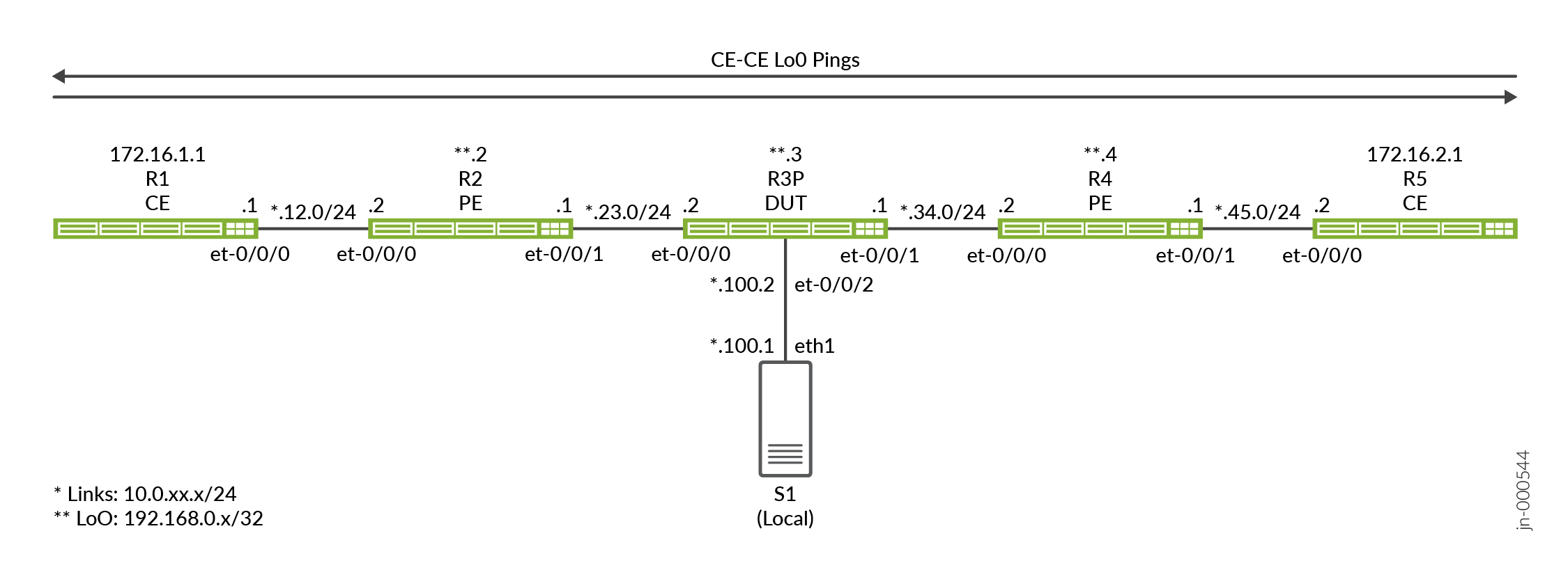
拓扑概述
在此示例中,R3 设备充当被测设备 (DUT),因为这是配置端口镜像的位置。设备使用防火墙过滤器来匹配与客户边缘设备关联的 IP 地址,以触发端口镜像作。入口和出口过滤器的组合用于镜像客户边缘设备(R1 和 R5)之间的请求和响应流量。
调用数据包采样的防火墙过滤器应用于 R3 设备上的一个或多个中转接口。
| 设备名称 | 角色 |
功能 |
| 客户边缘 | 客户边缘 (客户边缘) 设备,用于发送测试流量以确认采样是否正常工作。 | 这些设备被指定为客户边缘设备。大多数情况下,客户边缘设备是 VPN 服务的一部分。在这里,我们让客户边缘与提供商设备共享相同的 OSPF 区域 0,以提供主实例 IP 连接。 |
| PE | 连接到客户边缘的提供商边缘 (PE) 设备。 | 提供商网络边缘的设备。我们的 PE 仅运行 OSPF。未部署 BGP 和 VPN。 |
| P | 提供商 (P) 核心路由器。 | 我们选择在 P 路由器上演示端口镜像。您可以根据需要在任何提供商设备上配置端口镜像。 |
| 分析器 | 分析器设备接收镜像流量以进行存储和分析。 | 分析器的细节不在本文档的讨论范围内。有许多开源和商业选项可用。我们的分析器恰好运行的是 Centos 7.x,上面有一个支持 GUIO 版本的 Wireshark 的 Gnome 桌面。 |
拓扑图示
R3 配置步骤
有关导航 CLI 的信息,请参阅在 配置模式下使用 CLI 编辑器
有关所有设备上的完整配置,请参阅: 附录 2:在所有设备上设置命令
本节重点介绍配置 DUT(本例中的 P 设备 (R3))所需的主要配置任务。不包括用于采样的细节,所有设备都有类似的基准配置,支持主实例 IPv6 和 IPv4 连接。
-
配置 IPv4 和 IPv6 路由基准。这包括对 IPv4 和 IPv6 的环路接口和面向核心的接口进行编号。您还可以定义 OSPF 和 OSPFv3 路由协议,以便在所有网络接口之间提供可达性。
系统会为连接到分析器的接口配置被动 IGP 实例。这提供了用于诊断目的的可访问性,而无需在接口上生成 hello 数据包。分析器设备不需要也不需要 OSPF 邻接
[edit]
set interfaces et-0/0/0 unit 0 family inet address 10.0.23.2/24
set interfaces et-0/0/0 unit 0 family inet6 address 2001:db8:10:0:23::2/64
set interfaces et-0/0/1 unit 0 family inet address 10.0.34.1/24
set interfaces et-0/0/1 unit 0 family inet6 address 2001:db8:10:0:34::1/64
set interfaces et-0/0/2 unit 0 family inet address 10.0.100.2/24
set interfaces et-0/0/2 unit 0 family inet6 address 2001:db8:10:0:100::2/64
set interfaces lo0 unit 0 family inet address 192.168.0.3/32
set interfaces lo0 unit 0 family inet6 address 2001:db8:192:168:0::3/128

set routing-options router-id 192.168.0.3
set protocols ospf area 0.0.0.0 interface all
set protocols ospf area 0.0.0.0 interface fxp0.0 disable
set protocols ospf area 0 interface et-0/0/2.0 passive

set protocols ospf3 area 0.0.0.0 interface all
set protocols ospf3 area 0.0.0.0 interface fxp0.0 disable
set protocols ospf3 area 0 interface et-0/0/2.0 passive
注意:对于本地镜像用例,分析器和执行端口镜像的设备之间只需要 IP 连接。在此示例中,我们在连接到分析器的接口上运行无源 IGP。我们还在分析仪上配置一个默认路由,以便在分析仪和其他设备之间提供 IP 连接。这提供了测试分析仪与所有其他设备之间连接的能力。在拓扑中。在采样设备和分析器之间需要第 3 层可达性的远程端口镜像情况下,此功能最有用。
- 配置采样率。我们使用 1 的速率来选择并采样所有匹配的数据包。鉴于所有匹配的流量都已采样,默认值
run-length0 将保留不变。还必须指定将镜像流量发送到的出口接口和下一跃点地址。在此本地端口镜像示例中,应注意指定的接口和下一跳地址直接连接到 DUT。因此,在将镜像流量发送到分析器时,不需要也不需要隧道。[edit] set forwarding-options port-mirroring input rate 1 set forwarding-options port-mirroring family inet output interface et-0/0/2.0 next-hop 10.0.100.1 set forwarding-options port-mirroring family inet6 output interface et-0/0/2.0 next-hop 2001:db8:10:0:100::1
注意:此配置假定分析器回复 DUT 发送的 ARP 和 ND 请求,以进行 MAC 地址解析。如果不是这种情况,或者您希望 ARP 流量不属于数据包捕获的一部分,则应配置静态 ARP 条目。请务必为连接到 DUT 的分析器设备上的接口指定正确的 MAC 地址。
-
定义要匹配然后镜像 IPv4 数据包的防火墙过滤器。请注意,过滤器的作指定端口镜像作。此作会将匹配流量定向到之前配置的端口镜像实例。定义了两个过滤器,CE1 和 CE2 的源地址和目标地址各一个。过滤器包括计数功能,以帮助确认正确作。
不要忽略覆盖 Junos 防火墙过滤器默认作的
deny-all最后一个accept-all术语![edit] set firewall filter mirror_ce1 term term1 from source-address 172.16.1.1/32 set firewall filter mirror_ce1 term term1 from destination-address 172.16.2.1/32 set firewall filter mirror_ce1 term term1 then count mirror_ce1 set firewall filter mirror_ce1 term term1 then port-mirror set firewall filter mirror_ce1 term term1 then accept set firewall filter mirror_ce1 term accept-all then accept set firewall filter mirror_ce2 term term1 from source-address 172.16.2.1/32 set firewall filter mirror_ce2 term term1 from destination-address 172.16.1.1/32 set firewall filter mirror_ce2 term term1 then count mirror_ce2 set firewall filter mirror_ce2 term term1 then port-mirror set firewall filter mirror_ce2 term term1 then accept set firewall filter mirror_ce2 term accept-all then accept
-
定义防火墙过滤器以匹配和镜像 IPv6 数据包。
[edit]
set firewall family inet6 filter ce1_v6 term 1 from source-address 2001:db8:172:16:1::1/128
set firewall family inet6 filter ce1_v6 term 1 from destination-address 2001:db8:172:16:2::1/128
set firewall family inet6 filter ce1_v6 term 1 then count ce1_v6
set firewall family inet6 filter ce1_v6 term 1 then port-mirror
set firewall family inet6 filter ce1_v6 term 1 then accept
set firewall family inet6 filter ce1_v6 term accept-all then accept
set firewall family inet6 filter ce2_v6 term 1 from source-address 2001:db8:172:16:2::1/128
set firewall family inet6 filter ce2_v6 term 1 from destination-address 2001:db8:172:16:1::1/128
set firewall family inet6 filter ce2_v6 term 1 then count ce2_v6
set firewall family inet6 filter ce2_v6 term 1 then port-mirror
set firewall family inet6 filter ce2_v6 term 1 then accept
set firewall family inet6 filter ce2_v6 term accept-all then accept
-
将 IPv4 和 IPv6 过滤器应用于所需接口。在本例中,我们将这两个过滤器均应用于 et-0/0/0 接口。请注意过滤器应用的方向性。对于每个客户边缘流量(IPv4 或 IPv6),我们将一个过滤器应用为入口过滤器,另一个过滤器作为出口过滤器。这种应用方法与给定流量的地址分配和方向性的过滤器的编写方式兼容。
[edit]
set interfaces et-0/0/0 unit 0 family inet filter input mirror_ce1
set interfaces et-0/0/0 unit 0 family inet filter output mirror_ce2

set interfaces et-0/0/0 unit 0 family inet6 filter input ce1_v6
set interfaces et-0/0/0 unit 0 family inet6 filter output ce2_v6
验证
-
确认 OSPF 和 OSPF3 邻接方和路由到所有环路地址。
user@r3-ptx> show ospf neighbor

Address          Interface              State           ID               Pri  Dead
10.0.23.1        et-0/0/0.0             Full            192.168.0.2      128    31
10.0.34.2        et-0/0/1.0             Full            192.168.0.4      128    38

user@r3-ptx> show ospf3 neighbor

ID               Interface              State     Pri   Dead
192.168.0.2      et-0/0/0.0             Full      128     30
  Neighbor-address fe80::c6ba:25ff:fe48:9
192.168.0.4      et-0/0/1.0             Full      128     32
  Neighbor-address fe80::6204:30ff:fe6e:ffff

regress@r3-ptx> show route protocol ospf | match /32
172.16.1.1/32      *[OSPF/10] 01:04:02, metric 2
172.16.2.1/32      *[OSPF/10] 6d 00:47:07, metric 2
192.168.0.2/32     *[OSPF/10] 01:04:02, metric 1
192.168.0.4/32     *[OSPF/10] 6d 00:47:12, metric 1
224.0.0.5/32       *[OSPF/10] 6d 00:48:28, metric 1
224.0.0.6/32       *[OSPF/10] 6d 00:48:28, metric 1

regress@r3-ptx> show route protocol ospf3 | match /128
2001:db8:172:16:1::1/128
2001:db8:172:16:2::1/128
2001:db8:192:168::2/128*[OSPF3/10] 01:04:09, metric 1
2001:db8:192:168::4/128*[OSPF3/10] 6d 00:47:15, metric 1
ff02::5/128        *[OSPF3/10] 6d 00:48:35, metric 1
ff02::6/128        *[OSPF3/10] 6d 00:48:35, metric 1
-
确认 R3 上的端口镜像实例。验证镜像接口的端口镜像状态是否为
up。请务必确认upIPv4 和 IPv6 系列的状态。在此时,最好确认 DUT 和分析器之间的 IP 连接。在我们的设置中,分析器上配置了一个默认路由,以允许从网络的所有点进行 ping 测试。从技术上讲,分析器只需可通过 DUT (R3) 访问,因为这是本地端口镜像的一个示例。user@r3-ptx> show forwarding-options port-mirroring Instance Name: &global_instance Instance Id: 1 Input parameters: Rate : 1 Run-length : 0 Maximum-packet-length : 0 Output parameters: Family State Destination Next-hop inet up et-0/0/2.0 10.0.100.1 inet6 up et-0/0/2.0 2001:db8:10:0:100::1 -
清除 R3 上的防火墙计数器和接口统计信息。接下来,在客户边缘设备之间生成 IPv4 和 IPv6 测试流量,并在 R3 上显示防火墙计数器。验证应用于 R3 的过滤器是否正确反映测试流量。
user@r3-ptx> clear firewall all
user@r3-ptx> clear interfaces statistics all
user@r1-ptx> ping 172.16.2.1 source 172.16.1.1 count 10 rapid
PING 172.16.2.1 (172.16.2.1) from 172.16.1.1 : 56(84) bytes of data.
--- 172.16.2.1 ping statistics ---
10 packets transmitted, 10 received, 0% packet loss, time 711ms
rtt min/avg/max/mdev = 11.161/72.078/364.497/121.714 ms, ipg/ewma 78.945/100.962 ms

user@r1-ptx> ping 2001:db8:172:16:2::1 source 2001:db8:172:16:1::1 count 10 rapid
 ping 2001:db8:172:16:2::1 source 2001:db8:172:16:1::1 count 10 rapid
PING 2001:db8:172:16:2::1(2001:db8:172:16:2::1) from 2001:db8:172:16:1::1 : 56 data bytes

--- 2001:db8:172:16:2::1 ping statistics ---
10 packets transmitted, 10 received, 0% packet loss, time 2436ms
rtt min/avg/max/mdev = 11.363/247.188/518.314/226.132 ms, pipe 2, ipg/ewma 270.652/201.439 ms
-
显示 R3 上的防火墙计数器。验证应用于 R3 的过滤器是否正确反映了您生成的测试流量。
user@r3-ptx> show firewall
Filter: mirror_ce1
Counters:
Name                                                Bytes              Packets
mirror_ce1                                             840                   10

Filter: mirror_ce2
Counters:
Name                                                Bytes              Packets
mirror_ce2                                             840                   10

Filter: ce1_v6
Counters:
Name                                                Bytes              Packets
ce1_v6                                                1040                   10

Filter: ce2_v6
Counters:
Name                                                Bytes              Packets
ce2_v6                                                1040                   10
-
显示连接到分析器的 R3 的 et-0/0/2.0 接口的接口统计信息。目标是确认与生成的测试流量相关的输出流量计数器。IPv4 和 IPv6 都有 10 个 ping,并且考虑到我们同时镜像请求和回复,您可以期望看到大约 40 个输出数据包。
user@r3-ptx> show interfaces et-0/0/2.0 detail Logical interface et-0/0/2.0 (Index 1017) (SNMP ifIndex 541) (Generation 704374637676) Flags: Up SNMP-Traps Encapsulation: ENET2 Traffic statistics: Input bytes : 0 Output bytes : 3760 Input packets: 0 Output packets: 40 Local statistics: Input bytes : 0 Output bytes : 0 Input packets: 0 Output packets: 0 Transit statistics: Input bytes : 0 0 bps Output bytes : 3760 0 bps Input packets: 0 0 pps Output packets: 40 0 pps -
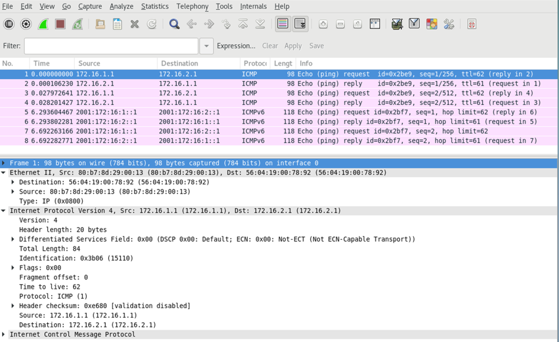
在监控站上运行 tcpdump 或您选择的分析应用程序,以确认镜像测试流量的接收和处理。为了使捕获的大小较小,我们生成了新的测试流量,每个 IPv4 和 IPv6 只有两个 ping 请求。捕获和解码可确认基于防火墙过滤器匹配的 IPv4 和 IPv6 端口镜像正在按预期工作。请注意,会同时显示请求和响应流量。
此外,在捕获过程中,请注意仅镜像第 3 层流量。所示第 2 层封装由 DUT (R3) 在将镜像流量转发至分析器时生成。当需要保留原始第 2 层帧时,可以为以太网交换或 VXLAN 等第 2 层服务配置端口镜像。
附录:在所有设备上设置命令
要快速配置此示例,请复制以下命令,将其粘贴到文本文件中,移除所有换行符,更改任何必要的详细信息以匹配您的网络配置,然后将命令复制粘贴到 [edit] 层级的 CLI 中。
R1(客户边缘)
set system host-name r1-ptx
set interfaces et-0/0/0 unit 0 family inet address 10.0.12.1/24
set interfaces et-0/0/0 unit 0 family inet6 address 2001:db8:10:0:12::1/64
set interfaces lo0 unit 0 family inet address 172.16.1.1/32
set interfaces lo0 unit 0 family inet6 address 2001:db8:172:16:1::1/128
set routing-options router-id 172.16.1.1
set protocols ospf area 0.0.0.0 interface all
set protocols ospf area 0.0.0.0 interface fxp0.0 disable
set protocols ospf3 area 0.0.0.0 interface all
set protocols ospf3 area 0.0.0.0 interface fxp0.0 disable
R2 (PE)
set system host-name r2-ptx
set interfaces et-0/0/0 unit 0 family inet address 10.0.12.2/24
set interfaces et-0/0/0 unit 0 family inet6 address 2001:db8:10:0:12::2/64
set interfaces et-0/0/1 unit 0 family inet address 10.0.23.1/24
set interfaces et-0/0/1 unit 0 family inet6 address 2001:db8:10:0:23::1/64
set interfaces et-0/0/2 unit 0 family inet tunnel-termination
set interfaces et-0/0/2 unit 0 family inet address 10.0.100.2/24
set interfaces lo0 unit 0 family inet address 192.168.0.2/32
set interfaces lo0 unit 0 family inet6 address 2001:db8:192:168:0::2/128
set routing-options router-id 192.168.0.2
set protocols ospf area 0.0.0.0 interface all
set protocols ospf area 0.0.0.0 interface fxp0.0 disable
set protocols ospf3 area 0.0.0.0 interface all
set protocols ospf3 area 0.0.0.0 interface fxp0.0 disable
R3 (DUT)
set system host-name r3-ptx
set interfaces et-0/0/0 unit 0 family inet filter input mirror_ce1
set interfaces et-0/0/0 unit 0 family inet filter output mirror_ce2
set interfaces et-0/0/0 unit 0 family inet address 10.0.23.2/24
set interfaces et-0/0/0 unit 0 family inet6 filter input ce1_v6
set interfaces et-0/0/0 unit 0 family inet6 filter output ce2_v6
set interfaces et-0/0/0 unit 0 family inet6 address 2001:db8:10:0:23::2/64
set interfaces et-0/0/1 unit 0 family inet address 10.0.34.1/24
set interfaces et-0/0/1 unit 0 family inet6 address 2001:db8:10:0:34::1/64
set interfaces et-0/0/2 unit 0 family inet address 10.0.100.2/24
set interfaces et-0/0/2 unit 0 family inet6 address 2001:db8:10:0:100::2/64
set interfaces lo0 unit 0 family inet address 192.168.0.3/32
set interfaces lo0 unit 0 family inet6 address 2001:db8:192:168:0::3/128
set forwarding-options port-mirroring input rate 1
set forwarding-options port-mirroring input run-length 0
set forwarding-options port-mirroring family inet output interface et-0/0/2.0 next-hop 10.0.100.1
set forwarding-options port-mirroring family inet6 output interface et-0/0/2.0 next-hop 2001:db8:10:0:100::1
set firewall family inet6 filter ce1_v6 term 1 from source-address 2001:db8:172:16:1::1/128
set firewall family inet6 filter ce1_v6 term 1 from destination-address 2001:db8:172:16:2::1/128
set firewall family inet6 filter ce1_v6 term 1 then count ce1_v6
set firewall family inet6 filter ce1_v6 term 1 then port-mirror
set firewall family inet6 filter ce1_v6 term 1 then accept
set firewall family inet6 filter ce1_v6 term accept-all then accept
set firewall family inet6 filter ce2_v6 term 1 from source-address 2001:db8:172:16:2::1/128
set firewall family inet6 filter ce2_v6 term 1 from destination-address 2001:db8:172:16:1::1/128
set firewall family inet6 filter ce2_v6 term 1 then count ce2_v6
set firewall family inet6 filter ce2_v6 term 1 then port-mirror
set firewall family inet6 filter ce2_v6 term 1 then accept
set firewall family inet6 filter ce2_v6 term accept-all then accept
set firewall filter mirror_ce1 term 1 from source-address 172.16.1.1/32
set firewall filter mirror_ce1 term 1 from destination-address 172.16.2.1/32
set firewall filter mirror_ce1 term 1 then count mirror_ce1
set firewall filter mirror_ce1 term 1 then port-mirror
set firewall filter mirror_ce1 term 1 then accept
set firewall filter mirror_ce1 term accept-all then accept
set firewall filter mirror_ce2 term term1 from source-address 172.16.2.1/32
set firewall filter mirror_ce2 term 1 from destination-address 172.16.1.1/32
set firewall filter mirror_ce2 term 1 then count mirror_ce2
set firewall filter mirror_ce2 term 1 then port-mirror
set firewall filter mirror_ce2 term 1 then accept
set firewall filter mirror_ce2 term accept-all  then accept
set routing-options router-id 192.168.0.3
set protocols ospf area 0.0.0.0 interface all
set protocols ospf area 0.0.0.0 interface fxp0.0 disable
set protocols ospf area 0.0.0.0 interface et-0/0/2.0 passive
set protocols ospf3 area 0.0.0.0 interface all
set protocols ospf3 area 0.0.0.0 interface fxp0.0 disable
set protocols ospf3 area 0.0.0.0 interface et-0/0/2.0 passive
R4 (PE)
set system host-name r4-ptx
set interfaces et-0/0/0 unit 0 family inet address 10.0.34.2/24
set interfaces et-0/0/0 unit 0 family inet6 address 2001:db8:10:0:34::2/64
set interfaces et-0/0/1 unit 0 family inet address 10.0.45.1/24
set interfaces et-0/0/1 unit 0 family inet6 address 2001:db8:10:0:45::1/64
set interfaces et-0/0/2 unit 0 family inet address 10.0.200.2/24
set interfaces et-0/0/2 unit 0 family inet6 address 2001:db8:10:0:200::2/64
set interfaces lo0 unit 0 family inet address 192.168.0.4/32
set interfaces lo0 unit 0 family inet6 address 2001:db8:192:168:0::4/128
set routing-options router-id 192.168.0.4
set protocols ospf area 0.0.0.0 interface all
set protocols ospf area 0.0.0.0 interface fxp0.0 disable
set protocols ospf3 area 0.0.0.0 interface all
set protocols ospf3 area 0.0.0.0 interface fxp0.0 disable
R5(客户边缘)
set system host-name r5-ptx
set interfaces et-0/0/0 unit 0 family inet address 10.0.45.2/24
set interfaces et-0/0/0 unit 0 family inet6 address 2001:db8:10:0:45::2/64
set interfaces lo0 unit 0 family inet address 172.16.2.1/32
set interfaces lo0 unit 0 family inet6 address 2001:db8:172:16:2::1/128
set routing-options router-id 172.16.2.1
set protocols ospf area 0.0.0.0 interface all
set protocols ospf area 0.0.0.0 interface fxp0.0 disable
set protocols ospf3 area 0.0.0.0 interface all
set protocols ospf3 area 0.0.0.0 interface fxp0.0 disable