基于下一跳的动态隧道
示例:配置基于下一跃点的 MPLS over UDP 动态隧道
此示例说明如何配置包含隧道复合下一跃点的动态 MPLS over UDP 隧道。MPLS over-UDP 功能在设备上支持的 IP 隧道数量上提供了扩展优势。
从 Junos OS 18.3R1 版开始,PTX 系列路由器和 QFX 系列交换机支持 MPLS over UDP 隧道。对于在 PTX 路由器或 QFX 交换机上配置的每个动态隧道,将创建一个隧道复合下一跃点、一个间接下一跃点和一个转发下一跃点来解析隧道目标路由。您还可以使用策略控制通过在层次结构级别包含 forwarding-rib 配置语句 [edit routing-options dynamic-tunnels] 来解析选定前缀上的动态隧道。
要求
此示例使用以下硬件和软件组件:
-
五个带有 MPC 和 MIC 的 MX 系列路由器。
-
在提供商边缘 (PE) 路由器上运行的 Junos OS 16.2 或更高版本。
准备工作:
-
配置设备接口,包括环路接口。
-
配置设备的路由器 ID 和自动系统编号。
-
与远程 PE 设备建立内部 BGP (IBGP) 会话。
-
在设备之间建立 OSPF 对等互连。
概述
从 Junos OS 16.2 版开始,动态 UDP 隧道支持为每个配置的 UDP 隧道创建隧道复合下一跃点。这些基于下一跃点的动态 UDP 隧道称为 MPLS over UDP 隧道。默认情况下,为 MPLS over UDP 隧道启用隧道复合下一跃点。
MPLS over UDP 隧道本质上可以是双向的,也可以是单向的。
-
双向 — 当 PE 设备通过 MPLS over UDP 隧道双向连接时,称为双向 MPLS over UDP 隧道。
-
单向 — 当两个 PE 设备通过 MPLS over UDP 隧道在一个方向上连接,在另一个方向上通过 MPLS/IGP 连接时,称为单向 MPLS-over-UDP 隧道。
单向 MPLS-over-UDP 隧道用于迁移场景,或者两个 PE 设备通过两个脱节网络提供相互连接的情况。由于单向 MPLS over UDP 隧道不存在反向隧道,因此您必须在远程 PE 设备上配置基于过滤器的 MPLS over UDP 解封装以转发流量。
从 Junos OS 18.2R1 版开始,在 PTX 系列路由器和具有单向 MPLS-over-UDP 隧道的 QFX10000 上,您必须为远程 PE 设备配置一个用于 MPLS-over-UDP 数据包的输入过滤器,以及一个用于解封装 IP 和 UDP 标头的操作,以便沿反向隧道方向转发数据包。
例如,在远程 PE 设备(设备 PE2)上,单向 MPLS over UDP 隧道需要以下配置:
PE2
[edit firewall filter]
user@host# set Decap_Filter term udp_decap from protocol udp
user@host# set Decap_Filter term udp_decap from destination-port 6635
user@host# set Decap_Filter term udp_decap then count UDP_PKTS
user@host# set Decap_Filter term udp_decap then decapsulate mpls-in-udp
user@host# set Decap_Filter term def then count def_pkt
user@host# set Decap_Filter term def then accept
在上述配置示例中, Decap_Filter 是用于 MPLS over UDP 解封装的防火墙过滤器的名称。该术语 udp_decap 是输入过滤器,用于在设备 PE2 面向核心的接口上接受 UDP 数据包,然后将 MPLS-over-UDP 数据包解封装为 MPLS-over-IP 数据包进行转发。
您可以使用现有的防火墙操作模式命令,例如 show firewall filter 查看基于过滤器的 MPLS over UDP 解封装。
例如:
user@host >show firewall filter Decap_Filter
Filter: Decap_Filter
Counters:
Name                                                Bytes              Packets
UDP_PKTS                                            16744                  149
def_pkt                                             13049                  136
对于基于 UDP 的单向 MPLS 隧道:
-
仅支持 IPv4 地址作为外部标头。基于过滤器的 MPLS over UDP 解封装不支持外部标头中的 IPv6 地址。
-
解封装后仅支持默认路由实例。
从 Junos OS 17.1 版开始,在带有 MPC 和 MIC 的 MX 系列路由器上,MPLS over UDP 隧道的扩展限制将会提高。
从 Junos 版本 19.2R1 开始,在配备 MPC 和 MIC 的 MX 系列路由器上,运营商支持运营商 (CSC) 架构可以部署为 MPLS-over-UDP 隧道,通过动态 IPv4 UDP 隧道传输 MPLS 流量,这些隧道在支持运营商的 PE 设备之间建立。通过此增强功能,MPLS over UDP 隧道提供的扩展优势将进一步增强。IPv6 UDP 隧道不支持对 MPLS-over-UDP 隧道的 CSC 支持。
现有的动态隧道功能需要完整的静态配置。目前,从通告路由中的对等设备接收的隧道信息将被忽略。从 Junos OS 17.4R1 版开始,在 MX 系列路由器上,基于下一跳的动态 MPLS-over-UDP 隧道使用 BGP 封装扩展社区发出信号。BGP 导出策略用于指定隧道类型、通告发送方侧隧道信息以及解析和传送接收方端隧道信息。根据接收到的类型隧道社区创建隧道。
BGP 支持多个隧道封装。收到多种功能后,将根据配置的 BGP 策略和隧道首选项创建基于下一跃点的动态隧道。对于要设置的隧道,隧道两端的隧道优先级应一致。默认情况下,MPLS over UDP 隧道优先于 GRE 隧道。如果存在动态隧道配置,则它优先于收到的隧道社区。
配置基于下一跃点的动态 MPLS over UDP 隧道时,请注意以下注意事项:
-
必须在 PE 设备之间配置 IBGP 会话。
-
允许在基于下一跃点的动态隧道封装(UDP 和 GRE)之间进行切换,这可能会影响每种模式下支持的 IP 隧道扩展值的网络性能。
-
对同一隧道目标同时使用基于 GRE 和 UDP 下一跃点的动态隧道封装类型会导致提交失败。
-
对于单向 MPLS over UDP 隧道,您必须在远程 PE 设备上显式配置基于过滤器的 MPLS over UDP 解封装,以便转发数据包。
-
MPLS-over-UDP 支持平滑路由引擎切换 (GRES),并且 MPLS-over-UDP 隧道类型标志符合统一的 ISSU 和 NSR。
-
精简模式下的虚拟 MX (vMX) 支持 MPLS over UDP 隧道。
-
MPLS over-UDP 隧道支持基于新的 IPv4 映射的 IPv6 下一跃点创建动态 GRE 隧道。
-
MPLS-over-UDP 隧道在与 contrail 的互操作性中受支持,其中 MPLS-over-UDP 隧道是从 contrail vRouter 创建的到 MX 网关。要启用此功能,需要在从 MX 系列路由器到 contrail vRouter 的路由中通告以下社区:
[edit policy-options community]
udp members 0x030c:64512:13;
在给定的时间点,contrail vRouter 仅支持一种隧道类型:基于下一跃点的动态 GRE 隧道、MPLS over UDP 隧道或 VXLAN。
-
基于下一跃点的动态 MPLS over UDP 隧道配置不支持以下功能:
-
RSVP 自动网格
-
普通 IPV6 GRE 和 UDP 隧道配置
-
逻辑系统
-
拓扑学
图 1 展示了通过动态 MPLS-over-UDP 隧道实现的第 3 层 VPN 场景。客户边缘 (CE) 设备 CE1 和 CE2 分别连接到提供商边缘 (PE) 设备 PE1 和 PE2。PE 设备连接到提供商设备(设备 P1),内部 BGP (IBGP) 会话互连两个 PE 设备。在 PE 设备之间配置了基于下一跃点的动态双向 MPL over UDP 隧道。
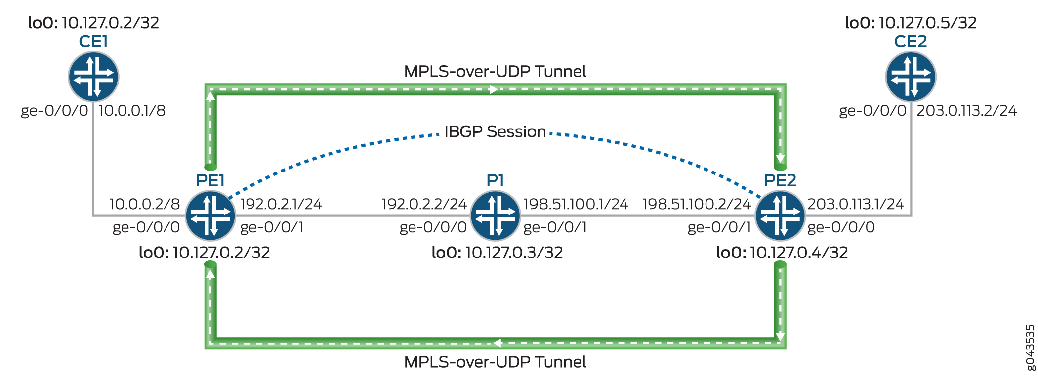
MPLS over-UDP 隧道的处理方式如下:
-
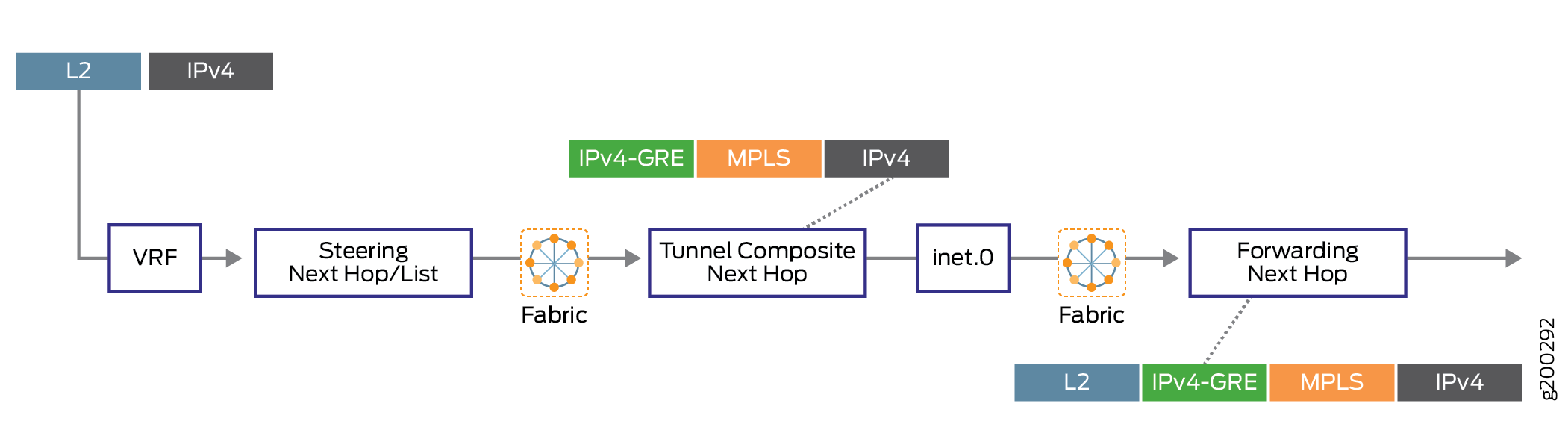
配置 MPLS over UDP 隧道后,将为 inet.3 路由表中的隧道创建具有隧道复合下一跃点的隧道目标掩码路由。仅当删除动态隧道配置时,才会撤销此 IP 隧道路由。
隧道复合下一跃点属性包括:
-
禁用第 3 层 VPN 复合下一跃点时 — 源地址和目标地址、封装字符串和 VPN 标签。
-
启用第 3 层 VPN 复合下一跃点和每前缀 VPN 标签分配时 — 源地址、目标地址和封装字符串。
-
启用第 3 层 VPN 复合下一跃点并禁用每前缀 VPN 标签分配时 - 源地址、目标地址和封装字符串。在这种情况下,路由将添加到具有辅助路由的其他虚拟路由和转发实例表中。
-
-
PE 设备使用 IBGP 会话互连。到远程 BGP 邻接方的 IBGP 路由下一跃点是协议下一跃点,可使用隧道掩码路由和隧道下一跃点进行解析。
-
通过隧道复合下一跃点解析协议下一跃点后,将创建带有转发下一跃点的间接下一跃点。
-
隧道复合下一跃点用于转发间接下一跃点的下一跃点。
配置
CLI 快速配置
要快速配置此示例,请复制以下命令,将其粘贴到文本文件中,删除所有换行符,更改详细信息,以便与网络配置匹配,将命令复制并粘贴到 [edit] 层级的 CLI 中,然后从配置模式进入 commit 。
CE1
set interfaces ge-0/0/0 unit 0 family inet address 10.0.0.1/8
set interfaces lo0 unit 0 family inet address 10.127.0.1/32
set routing-options router-id 10.127.0.1
set routing-options autonomous-system 65200
set protocols bgp group ce1-pe1 export export-loopback-direct
set protocols bgp group ce1-pe1 peer-as 100
set protocols bgp group ce1-pe1 neighbor 10.0.0.2
set policy-options policy-statement export-loopback-direct term term-1 from interface lo0.0
set policy-options policy-statement export-loopback-direct term term-1 from route-filter 10.127.0.1/32 exact
set policy-options policy-statement export-loopback-direct term term-1 then accept
CE2
set interfaces ge-0/0/0 unit 0 family inet address 203.0.113.2/24
set interfaces lo0 unit 0 family inet address 10.127.0.5/32
set routing-options router-id 10.127.0.5
set routing-options autonomous-system 65200
set protocols bgp group ce1-pe1 export export-loopback-direct
set protocols bgp group ce1-pe1 peer-as 65100
set protocols bgp group ce1-pe1 neighbor 203.0.113.1
set policy-options policy-statement export-loopback-direct term term-1 from interface lo0.0
set policy-options policy-statement export-loopback-direct term term-1 from route-filter 10.127.0.5/32 exact
set policy-options policy-statement export-loopback-direct term term-1 then accept
PE1
set interfaces ge-0/0/0 unit 0 family inet address 10.0.0.2/8
set interfaces ge-0/0/1 unit 0 family inet address 192.0.2.1/24
set interfaces ge-0/0/1 unit 0 family mpls
set interfaces lo0 unit 0 family inet address 10.127.0.2/32
set routing-options static route 10.33.0/16 next-hop 192.0.2.2
set routing-options router-id 10.127.0.2
set routing-options autonomous-system 65100
set routing-options forwarding-table export pplb
set routing-options dynamic-tunnels gre next-hop-based-tunnel
set routing-options dynamic-tunnels udp-dyn-tunnel-to-pe2 source-address 10.127.0.2
set routing-options dynamic-tunnels udp-dyn-tunnel-to-pe2 udp
set routing-options dynamic-tunnels udp-dyn-tunnel-to-pe2 destination-networks 10.127.0.0/24
set protocols bgp group IBGP type internal
set protocols bgp group IBGP local-address 10.127.0.2
set protocols bgp group IBGP family inet-vpn unicast
set protocols bgp group IBGP neighbor 10.127.0.4
set protocols ospf area 0.0.0.0 interface ge-0/0/1.0
set protocols ospf area 0.0.0.0 interface lo0.0 passive
set routing-instances MPLS-over-UDP-PE1 instance-type vrf
set routing-instances MPLS-over-UDP-PE1 interface ge-0/0/0.0
set routing-instances MPLS-over-UDP-PE1 route-distinguisher 10.127.0.2:1
set routing-instances MPLS-over-UDP-PE1 vrf-target target:600:1
set routing-instances MPLS-over-UDP-PE1 protocols bgp group pe1-ce1 peer-as 65200
set routing-instances MPLS-over-UDP-PE1 protocols bgp group pe1-ce1 neighbor 10.0.0.1 as-override
P1
set interfaces ge-0/0/0 unit 0 family inet address 192.0.2.2/24
set interfaces ge-0/0/0 unit 0 family mpls
set interfaces ge-0/0/1 unit 0 family inet address 198.51.100.1/24
set interfaces ge-0/0/1 unit 0 family mpls
set interfaces lo0 unit 0 family inet address 10.127.0.3/32
set routing-options router-id 10.127.0.3
set routing-options autonomous-system 65100
set protocols ospf area 0.0.0.0 interface ge-0/0/0.0
set protocols ospf area 0.0.0.0 interface ge-0/0/1.0
set protocols ospf area 0.0.0.0 interface lo0.0 passive
PE2
set interfaces ge-0/0/0 unit 0 family inet address 203.0.113.1/24
set interfaces ge-0/0/1 unit 0 family inet address 198.51.100.2/24
set interfaces ge-0/0/1 unit 0 family mpls
set interfaces lo0 unit 0 family inet address 10.127.0.4/8
set routing-options nonstop-routing
set routing-options router-id 10.127.0.4
set routing-options autonomous-system 65100
set routing-options forwarding-table export pplb
set routing-options dynamic-tunnels udp-dyn-tunnel-to-pe1 source-address 10.127.0.4
set routing-options dynamic-tunnels udp-dyn-tunnel-to-pe1 udp
set routing-options dynamic-tunnels udp-dyn-tunnel-to-pe1 destination-networks 10.127.0.0/24
set protocols bgp group IBGP type internal
set protocols bgp group IBGP local-address 10.127.0.4
set protocols bgp group IBGP family inet-vpn unicast
set protocols bgp group IBGP neighbor 10.127.0.2
set protocols ospf area 0.0.0.0 interface ge-0/0/1.0
set protocols ospf area 0.0.0.0 interface lo0.0 passive
set routing-instances MPLS-over-UDP-PE2 instance-type vrf
set routing-instances MPLS-over-UDP-PE2 interface ge-0/0/0.0
set routing-instances MPLS-over-UDP-PE2 route-distinguisher 10.127.0.4:1
set routing-instances MPLS-over-UDP-PE2 vrf-target target:600:1
set routing-instances MPLS-over-UDP-PE2 protocols bgp group ebgp peer-as 65200
set routing-instances MPLS-over-UDP-PE2 protocols bgp group ebgp neighbor 203.0.113.2 as-override
程序
分步过程
以下示例要求您在配置层次结构中导航各个级别。有关导航 CLI 的信息,请参阅 CLI 用户指南中的在配置模式下使用 CLI 编辑器。
要配置设备 PE1:
-
配置设备接口,包括设备的环路接口。
[edit interfaces]
user@PE1# set ge-0/0/0 unit 0 family inet address 10.0.0.2/8
user@PE1# set ge-0/0/1 unit 0 family inet address 192.0.2.1/24
user@PE1# set ge-0/0/1 unit 0 family mpls
user@PE1# set lo0 unit 0 family inet address 10.127.0.2/8
-
为来自设备 PE1 的路由配置静态路由,并将设备 P1 作为下一跃点目标。
[edit routing-options]
user@PE1# set static route 10.33.0.0/16 next-hop 192.0.2.2
-
配置设备 PE1 的路由器 ID 和自治系统编号。
[edit routing-options]
user@PE1# set router-id 10.127.0.2
user@PE1# set autonomous-system 65100
-
(仅限 PTX 系列)配置策略控制以解析通过选定前缀的 MPLS over UDP 动态隧道路由。
[edit routing-options dynamic-tunnels]
user@PTX-PE1# set forwarding-rib inet.0 inet-import dynamic-tunnel-fwd-route-import
-
(仅限 PTX 系列)配置 inet-import 策略以通过 解析动态隧道目标路由。
[edit policy-options]
user@PTX-PE1# set policy-statement dynamic-tunnel-fwd-route-import term 1 from route-filter 10.127.0.4/32 exact
user@PTX-PE1# set policy-statement dynamic-tunnel-fwd-route-import term 1 then accept
user@PTX-PE1# set policy-options policy-statement dynamic-tunnel-fwd-route-import then reject
-
配置 PE 设备之间的 IBGP 对等互连。
[edit protocols]
user@PE1# set bgp group IBGP type internal
user@PE1# set bgp group IBGP local-address 10.127.0.2
user@PE1# set bgp group IBGP family inet-vpn unicast
user@PE1# set bgp group IBGP neighbor 10.127.0.4
-
在设备 PE1 的所有接口上配置 OSPF,管理接口除外。
[edit protocols]
user@PE1# set ospf area 0.0.0.0 interface ge-0/0/1.0
user@PE1# set ospf area 0.0.0.0 interface lo0.0 passive
-
在设备 PE1 上启用基于下一跃点的动态 GRE 隧道配置。
注:此步骤仅用于说明基于下一跃点的动态 GRE 隧道与基于 UDP 的 MPLS 隧道之间的实现差异。
[edit routing-options]
user@PE1# set dynamic-tunnels gre next-hop-based-tunnel
-
配置从设备 PE1 到设备 PE2 的 MPLS over UDP 隧道参数。
[edit routing-options]
user@PE1# set dynamic-tunnels udp-dyn-tunnel-to-pe2 source-address 10.127.0.2
user@PE1# set dynamic-tunnels udp-dyn-tunnel-to-pe2 udp
user@PE1# set dynamic-tunnels udp-dyn-tunnel-to-pe2 destination-networks 10.127.0.0/24
-
在设备 PE1 和其他路由实例参数上配置 VRF 路由实例。
[edit routing-instances]
user@PE1# set MPLS-over-UDP-PE1 instance-type vrf
user@PE1# set MPLS-over-UDP-PE1 interface ge-0/0/0.0
user@PE1# set MPLS-over-UDP-PE1 route-distinguisher 10.127.0.2:1
user@PE1# set MPLS-over-UDP-PE1 vrf-target target:600:1
-
在路由实例配置中启用 BGP,以便与设备 CE1 对等互连。
[edit routing-instances]
user@PE1# set MPLS-over-UDP-PE1 protocols bgp group pe1-ce1 peer-as 65200
user@PE1# set MPLS-over-UDP-PE1 protocols bgp group pe1-ce1 neighbor 10.0.0.1 as-override
结果
在配置模式下,输入 show interfaces 、show routing-options、show protocols 和 show routing-instances 命令,以确认您的配置。如果输出未显示预期的配置,请重复此示例中的说明,以便进行更正。
user@PE1# show interfaces
ge-0/0/0 {
    unit 0 {
        family inet {
            address 10.0.0.2/8;
        }
    }
}
ge-0/0/1 {
    unit 0 {
        family inet {
            address 192.0.2.1/24;
        }
        family mpls;
    }
}
lo0 {
    unit 0 {
        family inet {
            address 10.127.0.2/32;
        }
    }
}
user@PE1# show routing-options
static {
    route 10.33.0.0/16 next-hop 192.0.2.2;
}
router-id 10.127.0.2;
autonomous-system 65100;
forwarding-table {
    export pplb;
}
dynamic-tunnels {
    gre next-hop-based-tunnel;
    udp-dyn-tunnel-to-pe2 {
        source-address 10.127.0.2;
        udp;
        destination-networks {
            10.127.0.0/24;
        }
    }
}
user@PE1# show protocols
bgp {
    group IBGP {
        type internal;
        local-address 10.127.0.2;
        family inet-vpn {
            unicast;
        }
        neighbor 10.127.0.4;
    }
}
ospf {
    area 0.0.0.0 {
        interface ge-0/0/1.0;
        interface lo0.0 {
            passive;
        }
    }
}
user@PE1# show routing-instances
MPLS-over-UDP-PE1 {
    instance-type vrf;
    interface ge-0/0/0.0;
    route-distinguisher 10.127.0.2:1;
    vrf-target target:600:1;
    protocols {
        bgp {
            group pe1-ce1 {
                peer-as 65200;
                neighbor 10.0.0.1 {
                    as-override;
                }
            }
        }
    }
}
如果完成设备配置,请从配置模式输入 commit。
验证
确认配置工作正常。
验证 PE 设备之间的连接
目的
验证设备 PE1 和设备 PE2 之间的 BGP 对等状态,以及从设备 PE2 接收的 BGP 路由。
操作
在操作模式下,运行 show bgp summary 和 show route receive-protocol bgp ip-address table bgp.l3vpn.0 命令。
user@PE1> show bgp summary
Groups: 2 Peers: 2 Down peers: 0
Table          Tot Paths  Act Paths Suppressed    History Damp State    Pending
bgp.l3vpn.0
                       2          2          0          0          0          0
Peer                     AS      InPkt     OutPkt    OutQ   Flaps Last Up/Dwn State|#Active/Received/Accepted/Damped...
10.127.0.4             65100        139        136       0       0       58:23 Establ
  bgp.l3vpn.0: 2/2/2/0
  MPLS-over-UDP-PE1.inet.0: 2/2/2/0
10.10.0.1               65200        135        136       0       0       58:53 Establ
MPLS-over-UDP-PE1.inet.0: 1/1/1/0user@PE1> show route receive-protocol bgp 10.127.0.4 table bgp.l3vpn.0 bgp.l3vpn.0: 2 destinations, 2 routes (2 active, 0 holddown, 0 hidden) Prefix Nexthop MED Lclpref AS path 10.127.0.4:1:127.0.0.5/8 * 10.127.0.4 65100 65200 I
意义
-
在第一个输出中,BGP 会话状态为
Establ,这意味着会话已启动且 PE 设备已对等互连。 -
在第二个输出中,设备 PE1 已从设备 PE2 获知 BGP 路由。
验证设备 PE1 上的动态隧道路由
目的
验证 inet.3 路由表中的路由以及设备 PE1 上的动态隧道数据库信息。
操作
在操作模式下,运行 show route table inet.3、 show dynamic-tunnels database terse、 show dynamic-tunnels database和 show dynamic-tunnels database summary 命令。
user@PE1> show route table inet.3
inet.3: 2 destinations, 2 routes (2 active, 0 holddown, 0 hidden)
+ = Active Route, - = Last Active, * = Both
10.127.0.0/24     *[Tunnel/300] 00:21:18
                      Tunnel
127.0.0.4/8     *[Tunnel/300] 00:21:18
Tunnel Compositeuser@PE1> show dynamic-tunnels database terse Table: inet.3 Destination-network: 10.127.0.0/24 Destination Source Next-hop Type Status 10.127.0.4/8 10.127.0.2 0xb395b10 nhid 613 udp Up
user@PE1> show dynamic-tunnels database
Table: inet.3
. . .
Tunnel to: 10.127.0.4/32
  Reference count: 2
  Next-hop type: UDP
    Source address: 10.127.0.2 Tunnel Id: 2
    Next hop: tunnel-composite, 0xb395b10, nhid 613
      VPN Label: Push 299776 Reference count: 3
      Traffic Statistics: Packets 0, Bytes 0
State: Upuser@PE1> show dynamic-tunnels database summary Dynamic Tunnels, Total 1 displayed GRE Tunnel: Active Tunnel Mode, Next Hop Base IFL Based, Total 0 displayed, Up 0, Down 0 Nexthop Based, Total 0 displayed, Up 0, Down 0 RSVP Tunnel: Total 0 displayed UDP Tunnel: Total 1 displayed, Up 1, Down 0
意义
-
在第一个输出中,由于设备 PE1 配置了 MPLS-over-UDP 隧道,因此将为 inet.3 路由表路由条目创建一个隧道复合路由。
-
在其余输出中,将显示 MPLS-over-UDP 隧道以及隧道封装类型、隧道下一跃点参数和隧道状态。
验证设备 PE2 上的动态隧道路由
目的
验证 inet.3 路由表中的路由以及设备 PE2 上的动态隧道数据库信息。
操作
在操作模式下,运行 show route table inet.3和命令 show dynamic-tunnels database terse 。
user@PE2> show route table inet.3
inet.3: 2 destinations, 2 routes (2 active, 0 holddown, 0 hidden)
+ = Active Route, - = Last Active, * = Both

10.127.0.0/24      *[Tunnel/300] 00:39:31
                      Tunnel
10.127.0.2/32     *[Tunnel/300] 00:24:53
Tunnel Compositeuser@PE1> show dynamic-tunnels database terse Table: inet.3 Destination-network: 127.0.0.0/8 Destination Source Next-hop Type Status 10.127.0.2/32 10.127.0.4 0xb395450 nhid 615 udp Up
意义
输出显示 MPLS over UDP 隧道的创建以及分配为下一跃点接口的下一跃点 ID,类似于设备 PE1。
验证路由是否具有预期的间接下一跃点标志
目的
验证设备 PE1 和设备 PE2 是否配置为在数据包转发引擎转发表上维护到转发下一跃点的间接下一跃点绑定。
操作
在操作模式下, show krt indirect-next-hop 在设备 PE1 和设备 PE2 上运行命令。
user@PE1> show krt indirect-next-hop
Indirect Nexthop:
Index: 1048574 Protocol next-hop address: 10.127.0.4
  RIB Table: bgp.l3vpn.0
  Label: Push 299776
  Policy Version: 1                     References: 1
  Locks: 3                              0xb2ab630
  Flags: 0x0
  INH Session ID: 0x0
  INH Version ID: 0
  Ref RIB Table: unknown
        Tunnel type: UDP, Reference count: 3, nhid: 613
        Destination address: 10.127.0.4, Source address: 10.127.0.2
        Tunnel id: 2, VPN Label: Push 299776, TTL action: prop-ttl
      IGP FRR Interesting proto count : 1
      Chain IGP FRR Node Num          : 1
         IGP Resolver node(hex)       : 0xb3c70dc
         IGP Route handle(hex)        : 0xb1ae688      IGP rt_entry protocol        : Tunnel
IGP Actual Route handle(hex) : 0x0 IGP Actual rt_entry protocol : Anyuser@PE2> show krt indirect-next-hop
Indirect Nexthop:
Index: 1048575 Protocol next-hop address: 10.127.0.2
RIB Table: bgp.l3vpn.0
Label: Push 299776
Policy Version: 1 References: 2
Locks: 3 0xb2ab740
Flags: 0x0
INH Session ID: 0x0
INH Version ID: 0
Ref RIB Table: unknown
Tunnel type: UDP, Reference count: 3, nhid: 615
Destination address: 10.127.0.2, Source address: 10.127.0.4
Tunnel id: 1, VPN Label: Push 299776, TTL action: prop-ttl
IGP FRR Interesting proto count : 2
Chain IGP FRR Node Num : 1
IGP Resolver node(hex) : 0xb3d3a28
IGP Route handle(hex) : 0xb1ae634 IGP rt_entry protocol : Tunnel
IGP Actual Route handle(hex) : 0x0 IGP Actual rt_entry protocol : Any意义
输出显示,在 PE 设备之间创建了一个基于下一跳的动态 MPLS over UDP 隧道。
故障排除
要对基于下一跃点的动态隧道进行故障排除,请参阅:
命令疑难解答
问题
基于下一跳的动态 MPLS 基于 UDP 隧道配置未生效。
解决方案
要对基于下一跃点的 MPLS over UDP 隧道配置进行故障排除,请在语句层次结构中使用[edit routing-options dynamic-tunnels]以下命令traceroute:
-
traceoptions file file-name -
traceoptions file size file-size -
traceoptions flag all
例如:
[edit routing-options dynamic-tunnels]
traceoptions {
    file udp_dyn_pe1.wri size 4294967295;
    flag all;
}
基于下一跳的动态隧道的反欺骗保护概述
随着大规模 IP 隧道在数据中心部署的增加,需要添加安全措施,允许用户限制来自受损虚拟机 (VM) 的恶意流量。一种可能的攻击是通过网关路由器将流量从受感染的服务器注入任意客户 VPN。在这种情况下,对 IP 隧道的反欺骗检查可确保只有合法来源才将流量从其指定的 IP 隧道注入数据中心。
基于下一跳跃的动态 IP 隧道会为设备上创建的每条动态隧道创建一个隧道复合下一跃点。由于基于下一跳的动态隧道消除了配置的每个新动态隧道对物理接口的依赖,因此配置基于下一跃点的动态隧道比可在设备上创建的动态隧道数量具有扩展优势。从 Junos OS 17.1 版开始,基于下一跃点的动态隧道为基于下一跃点的动态 IP 隧道提供了反欺骗功能。通过此增强功能,将实施一项安全措施,以防止流量通过网关路由器从受感染的服务器注入任意客户 VPN。
反欺骗是使用数据包转发引擎中的反向路径转发检查实现的。将对通过隧道到达路由实例的流量实施检查。目前,当网关路由器从隧道接收流量时,只有目标查找我们完成并相应地转发数据包。启用反欺骗保护后,除了查找隧道目标外,网关路由器还会对 VPN 中的封装数据包 IP 标头执行源地址查找。这可以确保合法源通过其指定的 IP 隧道注入流量。因此,反欺骗保护可确保从指定隧道上的合法来源接收隧道流量。
图 2 说明了具有反欺骗保护要求的示例拓扑。
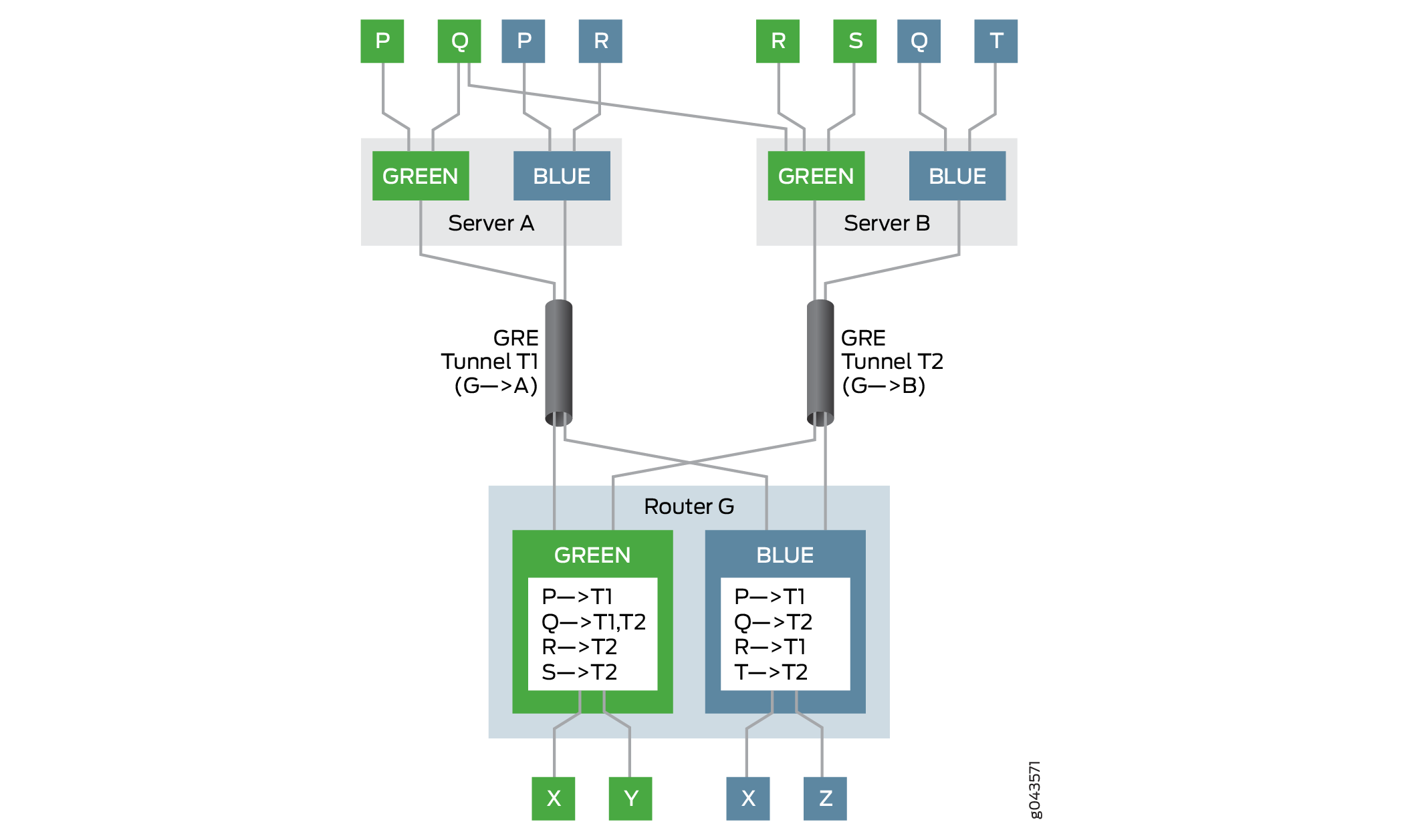
在此示例中,网关路由器是路由器 G.路由器 G 有两个 VPN:绿色和蓝色。服务器 A 和服务器 B 这两台服务器可以分别通过基于下一跳的动态隧道 T1 和 T2 到达路由器 G 上的绿色和蓝色 VPN。连接到服务器的多个主机和虚拟机(P、Q、R、S 和 T)可以通过网关路由器 G 访问 VPN.路由器 G 具有绿色和蓝色 VPN 的虚拟路由和转发 (VRF) 表,每个表都填充了这些 VPN 中虚拟机的可访问性信息。
例如,在 VPN Green 中,路由器 G 使用隧道 T1 到达主机 P,使用隧道 T2 到达主机 R 和 S,并在隧道 T1 和 T2 之间完成负载平衡以到达多宿主主机 Q。在 VPN Blue 中,路由器 G 使用隧道 T1 到达主机 P 和 R,使用隧道 T2 到达主机 Q 和 T。
在以下情况下,反向路径转发的检查通过:
数据包来自其指定隧道上的合法来源。
VPN Green 中的主机 P 使用隧道 T1 向主机 X 发送数据包。由于路由器 G 可以通过隧道 T1 到达主机 P,因此它允许数据包传递数据包并将其转发到主机 X。
数据包来自其指定隧道上的多宿主源。
VPN Green 中的主机 Q 在服务器 A 和 B 上是多宿主的,可以通过隧道 T1 和 T2 到达路由器 G。主机 Q 使用隧道 T1 向主机 Y发送数据包,并使用隧道 T2 向主机 X 发送数据包。由于路由器 G 可以通过隧道 T1 和 T2 到达主机 Q,因此它允许数据包分别传递并转发给主机 Y 和 X。
默认情况下,第 3 层 VPN 未启用反欺骗保护。要为基于下一跃点的动态隧道启用反欺骗,请在层次结构级别包含 ip-tunnel-rpf-check 语句 [edit routing-instances routing-instance-name routing-options forwarding-table] 。反向路径转发检查仅适用于 VRF 路由实例。默认模式设置为 strict,其中来自非指定隧道上的源的数据包未通过检查。可以将 ip-tunnel-rpf-check 模式设置为 loose,当数据包来自不存在的源时,反向路径转发检查将失败。可以在语句下 ip-tunnel-rpf-check 配置可选的防火墙过滤器,以计算和记录未通过反向路径转发检查的数据包。
以下示例输出显示了反欺骗配置:
[edit routing-instances routing-instance-name routing-options forwarding-table]
ip-tunnel-rpf-check {
    mode loose;
    fail-filter filter-name;
}
为基于下一跃点的动态隧道配置反欺骗保护时,请考虑以下准则:
只能为 IPv4 隧道和 IPv4 数据流量启用反欺骗保护。IPv6 隧道和 IPv6 数据流量不支持反欺骗功能。
基于下一跃点的动态隧道的反欺骗可以检测并防止遭到入侵的虚拟机(内部源反向路径转发检查),但不能检测并防止遭到入侵的标签欺骗服务器。
基于下一跃点的 IP 隧道可以在 inet.0 路由表上发起和终止。
当 VRF 路由实例具有标签交换接口 (LSI)(使用
vrf-table-label)或虚拟隧道 (VT) 接口时,反欺骗保护有效。如果 VRF 路由实例上有标签,则per-next-hop不支持反欺骗保护。仅适用于
rpf fail-filter内部 IP 数据包。启用反欺骗检查不会影响设备上基于下一跃点的动态隧道的扩展限制。
为 VRF 路由实例启用反欺骗保护的系统资源利用率略高于未启用反欺骗保护的基于下一跃点的动态隧道的利用率。
反欺骗保护需要额外的源 IP 地址检查,这对网络性能的影响最小。
平滑路由引擎切换 (GRES) 和服务中软件升级 (ISSU) 受反欺骗保护支持。
示例:为基于下一跳的动态隧道配置反欺骗保护
此示例说明如何为虚拟路由和转发 (VRF) 路由实例配置反向路径转发检查,以便为基于下一跃点的动态隧道启用反欺骗保护。这些检查可确保合法源通过其指定的 IP 隧道注入流量。
要求
此示例使用以下硬件和软件组件:
三个带 MIC 的 MX 系列路由器,每个路由器都连接到一个主机设备。
在一个或所有路由器上运行的 Junos OS 17.1 或更高版本。
准备工作:
在灵活 PIC 集中器上启用隧道服务配置。
配置路由器接口。
配置路由器 ID 并为路由器分配自治系统编号。
建立与隧道端点的内部 BGP (IBGP) 会话。
在所有路由器上配置 RSVP。
在所有路由器上配置 OSPF 或任何其他内部网关协议。
在两个路由器之间配置两个基于下一跃点的动态 IP 隧道。
为每个路由器到主机连接配置 VRF 路由实例。
概述
从 Junos OS 17.1 版开始,反欺骗功能将添加到基于下一跃点的动态 IP 隧道中,其中使用数据包转发引擎中的反向路径转发来检查通过隧道到达路由实例的流量。
目前,当网关路由器从隧道接收流量时,仅在转发之前完成目标地址查找。借助反欺骗保护,网关路由器会对 VPN 中的封装数据包 IP 标头执行源地址查找,以确保合法源通过其指定的 IP 隧道注入流量。这称为严格模式,是反欺骗保护的默认行为。要传递来自非指定隧道的流量,将在丢失模式下启用反向路径转发检查。对于从不存在的源接收的流量,严格模式和松散模式的反向路径转发检查都会失败。
VRF 路由实例支持反欺骗。要为动态隧道启用反欺骗,请在层次结构级别包含 ip-tunnel-rpf-check 语句 [edit routing-instances routing-instance-name routing-options forwarding-table] 。
拓扑学
图 3 说明了启用了反欺骗保护的示例网络拓扑。路由器 R0、R1 和 R2 分别连接到主机 Host0、Host1 和主机 2。两个基于下一跃点的通用路由封装 (GRE) 动态隧道(隧道 1 和隧道 2)分别将路由器 R0 与路由器 R1 和 R2 连接。VRF 路由实例在每个路由器及其连接的主机设备之间运行。
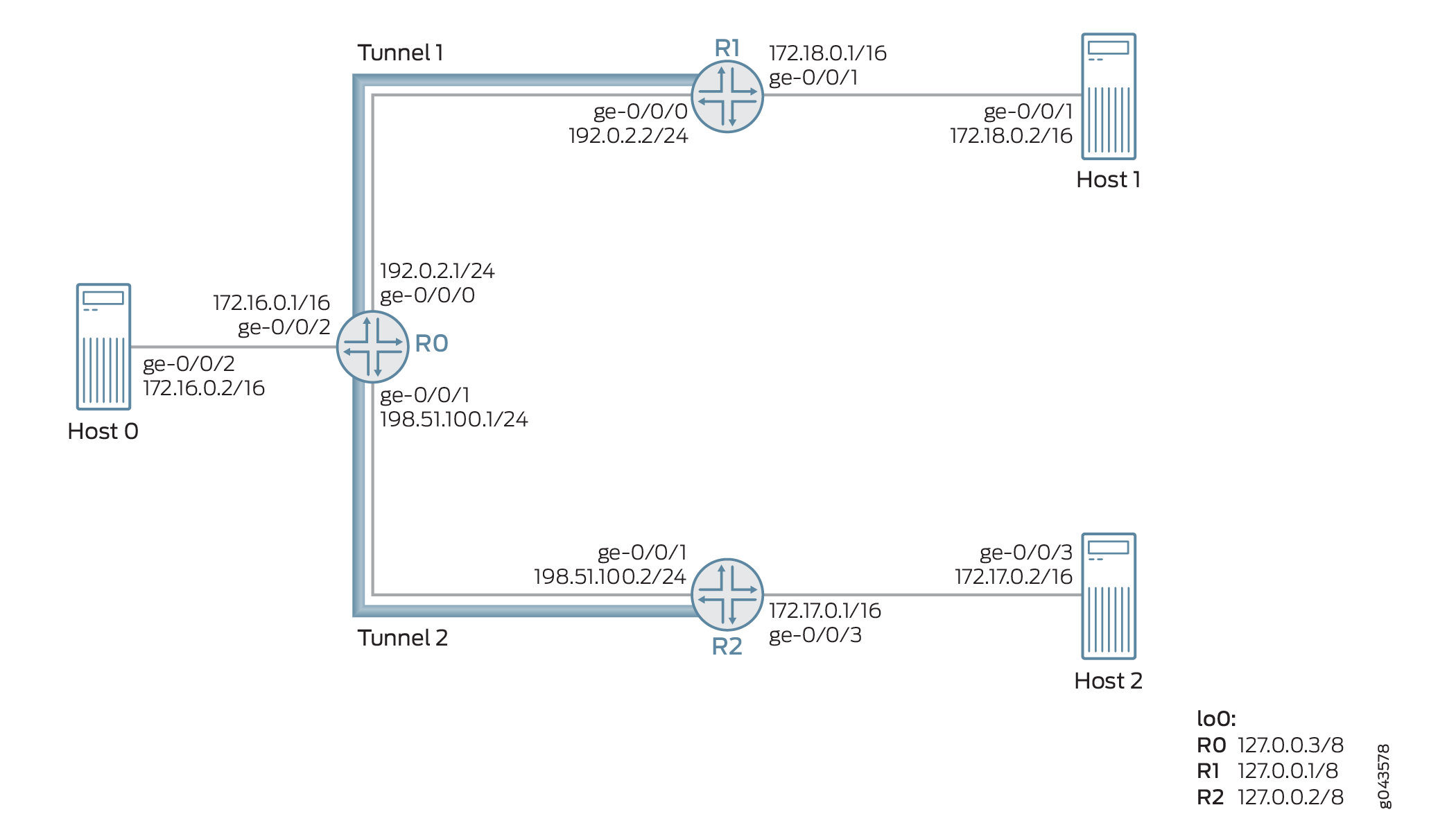
例如,路由器 0 上通过基于下一跳的动态 GRE 隧道(隧道 2)从路由器 R2 接收三个数据包(数据包 A、B 和 C)。这些数据包的源 IP 地址为 172.17.0.2(数据包 A)、172.18.0.2(数据包 B)和 172.20.0.2(数据包 C)。
数据包 A 和 B 的源 IP 地址分别属于主机 2 和主机 1。数据包 C 是不存在的源隧道。此示例中的指定隧道为隧道 2,未指定隧道为隧道 1。因此,按如下方式处理数据包:
Packet A— 由于源来自指定的隧道(隧道 2),因此数据包 A 通过反向路径转发检查,并进行处理以通过隧道 2 进行转发。
Packet B— 由于源来自隧道 1(即非预定隧道),因此默认情况下,数据包 B 在严格模式下无法通过反向路径转发检查。如果启用了松散模式,则允许数据包 B 进行转发。
Packet C— 由于源是不存在的隧道源,因此数据包 C 无法通过反向路径转发检查,并且数据包不会被转发。
配置
CLI 快速配置
要快速配置此示例,请复制以下命令,将其粘贴到文本文件中,删除所有换行符,更改详细信息,以便与网络配置匹配,将命令复制并粘贴到 [edit] 层级的 CLI 中,然后从配置模式进入 commit 。
路由器 R0
set interfaces ge-0/0/0 unit 0 family inet address 192.0.2.1/24
set interfaces ge-0/0/1 unit 0 family inet address 198.51.100.1/24
set interfaces ge-0/0/2 vlan-tagging
set interfaces ge-0/0/2 unit 0 vlan-id 1
set interfaces ge-0/0/2 unit 0 family inet address 172.16.0.1/16
set interfaces lo0 unit 0 family inet address 10.1.1.1/32
set routing-options router-id 10.1.1.1
set routing-options autonomous-system 100
set routing-options dynamic-tunnels gre next-hop-based-tunnel
set routing-options dynamic-tunnels T1 source-address 192.0.2.1
set routing-options dynamic-tunnels T1 gre
set routing-options dynamic-tunnels T1 destination-networks 192.0.2.0/24
set routing-options dynamic-tunnels T2 source-address 198.51.100.1
set routing-options dynamic-tunnels T2 gre
set routing-options dynamic-tunnels T2 destination-networks 198.51.100.0/24
set protocols rsvp interface all
set protocols rsvp interface fxp0.0 disable
set protocols bgp group IBGP type internal
set protocols bgp group IBGP local-address 10.1.1.1
set protocols bgp group IBGP family inet-vpn unicast
set protocols bgp group IBGP neighbor 20.1.1.1
set protocols bgp group IBGP neighbor 30.1.1.1
set protocols ospf traffic-engineering
set protocols ospf area 0.0.0.0 interface lo0.0 passive
set protocols ospf area 0.0.0.0 interface all
set routing-instances VPN1 instance-type vrf
set routing-instances VPN1 interface ge-0/0/2.0
set routing-instances VPN1 route-distinguisher 100:100
set routing-instances VPN1 vrf-target target:100:1
set routing-instances VPN1 vrf-table-label
set routing-instances VPN1 routing-options forwarding-table ip-tunnel-rpf-check mode strict
set routing-instances VPN1 protocols bgp group External type external
set routing-instances VPN1 protocols bgp group External family inet unicast
set routing-instances VPN1 protocols bgp group External peer-as 200
set routing-instances VPN1 protocols bgp group External neighbor 172.16.0.1
路由器 R1
set interfaces ge-0/0/0 unit 0 family inet address 192.0.2.2/24
set interfaces ge-0/0/1 vlan-tagging
set interfaces ge-0/0/1 unit 0 vlan-id 2
set interfaces ge-0/0/1 unit 0 family inet address 172.18.0.1/16
set interfaces lo0 unit 0 family inet address 20.1.1.1/32
set routing-options router-id 20.1.1.1
set routing-options autonomous-system 100
set routing-options dynamic-tunnels gre next-hop-based-tunnel
set routing-options dynamic-tunnels T1 source-address 192.0.2.2
set routing-options dynamic-tunnels T1 gre
set routing-options dynamic-tunnels T1 destination-networks 192.0.2.0/24
set protocols rsvp interface all
set protocols rsvp interface fxp0.0 disable
set protocols bgp group IBGP type internal
set protocols bgp group IBGP local-address 20.1.1.1
set protocols bgp group IBGP family inet-vpn unicast
set protocols bgp group IBGP neighbor 30.1.1.1
set protocols bgp group IBGP neighbor 10.1.1.1
set protocols ospf traffic-engineering
set protocols ospf area 0.0.0.0 interface lo0.0 passive
set protocols ospf area 0.0.0.0 interface all
set routing-instances VPN2 instance-type vrf
set routing-instances VPN2 interface ge-0/0/1.0
set routing-instances VPN2 route-distinguisher 100:200
set routing-instances VPN2 vrf-target target:200:1
set routing-instances VPN2 vrf-table-label
R2
set interfaces ge-0/0/1 unit 0 family inet address 198.51.100.2/24
set interfaces ge-0/0/2 vlan-tagging
set interfaces ge-0/0/2 unit 0 vlan-id 3
set interfaces ge-0/0/2 unit 0 family inet address 172.17.0.1/16
set interfaces lo0 unit 0 family inet address 30.1.1.1/32
set routing-options router-id 30.1.1.1
set routing-options autonomous-system 100
set routing-options dynamic-tunnels gre next-hop-based-tunnel
set routing-options dynamic-tunnels T2 source-address 198.51.100.2
set routing-options dynamic-tunnels T2 gre
set routing-options dynamic-tunnels T2 destination-networks 198.51.100.0/24
set protocols rsvp interface all
set protocols rsvp interface fxp0.0 disable
set protocols bgp group IBGP type internal
set protocols bgp group IBGP local-address 30.1.1.1
set protocols bgp group IBGP family inet-vpn unicast
set protocols bgp group IBGP neighbor 20.1.1.1
set protocols bgp group IBGP neighbor 10.1.1.1
set protocols ospf traffic-engineering
set protocols ospf area 0.0.0.0 interface lo0.0 passive
set protocols ospf area 0.0.0.0 interface all
set routing-instances VPN3 instance-type vrf
set routing-instances VPN3 interface ge-0/0/2.0
set routing-instances VPN3 route-distinguisher 100:300
set routing-instances VPN3 vrf-target target:300:1
set routing-instances VPN3 vrf-table-label
程序
分步过程
以下示例要求您在配置层次结构中导航各个级别。有关导航 CLI 的信息,请参阅 CLI 用户指南中的在配置模式下使用 CLI 编辑器。
要配置路由器 R0:
配置路由器 R0 的接口,包括环路接口。
[edit interfaces]
user@R0# set ge-0/0/0 unit 0 family inet address 192.0.2.1/24
user@R0# set ge-0/0/1 unit 0 family inet address 198.51.100.1/24
user@R0# set ge-0/0/2 vlan-tagging
user@R0# set ge-0/0/2 unit 0 vlan-id 1
user@R0# set ge-0/0/2 unit 0 family inet address 172.16.0.1/16
user@R0# set lo0 unit 0 family inet address 10.1.1.1/32
为路由器 R0 分配路由器 ID 和自治系统编号。
[edit routing-options]
user@R0# set router-id 10.1.1.1
user@R0# set autonomous-system 100
配置路由器之间的 IBGP 对等互连。
[edit protocols]
user@R0# set bgp group IBGP type internal
user@R0# set bgp group IBGP local-address 10.1.1.1
user@R0# set bgp group IBGP family inet-vpn unicast
user@R0# set bgp group IBGP neighbor 20.1.1.1
user@R0# set bgp group IBGP neighbor 30.1.1.1
在路由器 R0 的所有接口(管理接口除外)上配置 OSPF。
[edit protocols]
user@R0# set ospf traffic-engineering
user@R0# set ospf area 0.0.0.0 interface lo0.0 passive
user@R0# set ospf area 0.0.0.0 interface all
在路由器 R0 的所有接口上配置 RSVP,管理接口除外。
[edit protocols]
user@R0# set rsvp interface all
user@R0# set rsvp interface fxp0.0 disable
在路由器 R0 上启用基于下一跃点的动态 GRE 隧道配置。
[edit routing-options]
user@R0# set dynamic-tunnels gre next-hop-based-tunnel
配置从路由器 R0 到路由器 R1 的动态 GRE 隧道参数。
[edit routing-options]
user@R0# set dynamic-tunnels T1 source-address 192.0.2.1
user@R0# set dynamic-tunnels T1 gre
user@R0# set dynamic-tunnels T1 destination-networks 192.0.2.0/24
配置从路由器 R0 到路由器 R2 的动态 GRE 隧道参数。
[edit routing-options]
user@R0# set dynamic-tunnels T2 source-address 198.51.100.1
user@R0# set dynamic-tunnels T2 gre
user@R0# set dynamic-tunnels T2 destination-networks 198.51.100.0/24
在路由器 R0 上配置虚拟路由和转发 (VRF) 路由实例,并将连接到主机 1 的接口分配给 VRF 实例。
[edit routing-instances]
user@R0# set VPN1 instance-type vrf
user@R0# set VPN1 route-distinguisher 100:100
user@R0# set VPN1 vrf-target target:100:1
user@R0# set VPN1 vrf-table-label
user@R0# set VPN1 interface ge-0/0/2.0
为 VRF 路由实例配置与主机 1 的外部 BGP 会话。
[edit routing-instances]
user@R0# set VPN1 protocols bgp group External type external
user@R0# set VPN1 protocols bgp group External family inet unicast
user@R0# set VPN1 protocols bgp group External peer-as 200
user@R0# set VPN1 protocols bgp group External neighbor 172.16.0.1
为路由器 R0 上的 VRF 路由实例配置反欺骗保护。这样可以对路由器 0 上基于下一跃点的动态隧道 T1 和 T2 启用反向路径转发检查。
[edit routing-instances]
user@R0# set VPN1 routing-options forwarding-table ip-tunnel-rpf-check mode strict
结果
在配置模式下,输入 show interfaces 、show routing-options、show protocols 和 show routing-options 命令,以确认您的配置。如果输出未显示预期的配置,请重复此示例中的说明,以便进行更正。
user@R0# show interfaces
ge-0/0/0 {
    unit 0 {
        family inet {
            address 192.0.2.1/24;
        }
    }
}
ge-0/0/1 {
    unit 0 {
        family inet {
            address 198.51.100.1/24;
        }
    }
}
ge-0/0/2 {
    vlan-tagging;
    unit 0 {
        vlan-id 1;
        family inet {
            address 172.16.0.1/16;
        }
    }
}
lo0 {
    unit 0 {
        family inet {
            address 10.1.1.1/32;
        }
    }
}
user@R0# show routing-options
router-id 10.1.1.1;
autonomous-system 100;
dynamic-tunnels {
    gre next-hop-based-tunnel;
    T1 {
        source-address 192.0.2.1;
        gre;
        destination-networks {
            192.0.2.0/24;
        }
    }
    T2 {
        source-address 198.51.100.1;
        gre;
        destination-networks {
            198.51.100.0/24;
        }
    }
}
user@R0# show protocols
rsvp {
    interface all;
    interface fxp0.0 {
        disable;
    }
}
bgp {
    group IBGP {
        type internal;
        local-address 10.1.1.1;
        family inet-vpn {
            unicast;
        }
        neighbor 20.1.1.1;
        neighbor 30.1.1.1;
    }
}
ospf {
    traffic-engineering;
    area 0.0.0.0 {
        interface lo0.0 {
            passive;
        }
        interface all;
    }
}
user@R0# show routing-instances
VPN1 {
    instance-type vrf;
    interface ge-0/0/2.0;
    route-distinguisher 100:100;
    vrf-target target:100:1;
    vrf-table-label;
    routing-options {
        forwarding-table {
            ip-tunnel-rpf-check {
                mode strict;
            }
        }
    }
    protocols {
        bgp {
            group External {
                type external;
                family inet {
                    unicast;
                }
                peer-as 200;
                neighbor 172.16.0.1;
            }
        }
    }
}
验证
确认配置工作正常。
验证基本配置
目的
验证路由器 R0 与路由器 R1 和 R2 之间的 OSPF 和 BGP 对等状态。
操作
在操作模式下,运行 show ospf neighbor 和 show bgp summary命令。
user@R0> show ospf neighbor
Address          Interface              State     ID               Pri  Dead
192.0.2.2        ge-0/0/0.0             Full      20.1.1.1         128    32
198.51.100.2     ge-0/0/1.0             Full      30.1.1.1         128    32

user@R0> show bgp summary
Groups: 2 Peers: 3 Down peers: 1
Table          Tot Paths  Act Paths Suppressed    History Damp State    Pending
bgp.l3vpn.0
                       0          0          0          0          0          0
Peer                     AS      InPkt     OutPkt    OutQ   Flaps Last Up/Dwn State|#Active/Received/Accepted/Damped...
20.1.1.1                100        182        178       0       0     1:20:27 Establ
  bgp.l3vpn.0: 0/0/0/0
30.1.1.1                100        230        225       0       0     1:41:51 Establ
  bgp.l3vpn.0: 0/0/0/0
172.16.0.1              200          0          0       0       0     1:42:08 Establ
意义
OSPF 和 BGP 会话在路由器 R0、R1 和 R2 之间启动并运行。
验证动态隧道配置
目的
验证路由器 R0 与路由器 R1 和 R2 之间基于下一跃点的动态 GRE 隧道的状态。
操作
在操作模式下,运行 show route table inet.3和命令 show dynamic-tunnels database terse 。
user@R0> show route table inet.3

inet.3: 2 destinations, 2 routes (2 active, 0 holddown, 0 hidden)
+ = Active Route, - = Last Active, * = Both

192.0.2.0/24       *[Tunnel/300] 01:47:57
                      Tunnel
192.0.2.2/24       *[Tunnel/300] 01:47:57
                      Tunnel Composite

198.51.100.0/24    *[Tunnel/300] 01:47:57
                      Tunnel
198.51.100.2/24    *[Tunnel/300] 01:47:57
Tunnel Compositeuser@R0> show dynamic-tunnels database terse Table: inet.3 Destination-network: 192.0.2.0/24 Destination Source Next-hop Type Status 192.0.2.2/24 192.0.2.1 0xb395e70 nhid 612 gre Up Destination-network: 198.51.100.0/24 Destination Source Next-hop Type Status 198.51.100.2 198.51.100.1 0xb395e70 nhid 612 gre Up
意义
两个基于下一跃点的动态 GRE 隧道(隧道 1 和隧道 2)已启动。
验证反欺骗保护配置
目的
验证是否已在路由器 R0 上的 VRF 路由实例上启用反向路径转发检查。
操作
在操作模式下,运行 show krt table VPN1.inet.0 detail.
user@R0> show krt table VPN1.inet.0 detail
KRT tables:
VPN1.inet.0                   : GF: 1 krt-index: 8     ID: 0 kernel-id: 8
        flags: (null)
        tunnel rpf config data : enable, strict, filter [0], 0x2
        tunnel rpf tlv data : enable, strict, filter [0], 0x4
        unicast reverse path: disabled
        fast-reroute-priority: 0
        Permanent NextHops
          Multicast        : 0 Broadcast : 0
          Receive          : 0   Discard   : 0
          Multicast Discard: 0   Reject    : 0
          Local            : 0   Deny      : 0
          Table            : 0
意义
在严格模式下,在 VRF 路由实例上启用配置的反向路径转发检查。
基于下一跳的动态隧道定位概述
基于下一跃点的动态隧道包括通用路由封装 (GRE) 隧道和 MPLS-over-UDP 隧道。与基于接口的隧道相比,这些隧道具有扩展优势。但是,与基于接口的隧道不同,基于下一跳跃的动态隧道本质上是无锚的,隧道的转发信息将分发到设备上每个线卡上的数据包转发引擎 (PFE)。这会将设备上支持的最大隧道数限制为单个线卡的隧道容量。借助对本地化的支持,您可以配置基于下一跃点的动态隧道本地化,以仅在指定为锚点 PFE 的线卡的 PFE 上创建转发信息。设备上其他线卡上的 PFE 具有状态转发信息,用于将数据包引导至锚点 PFE。这通过增加设备上支持的最大隧道数来提供扩展优势。
- 基于下一跳的动态隧道定位的优势
- 基于下一跳的动态隧道定位用例
- 通过定位基于下一跳的动态隧道实现流量处理
- 配置基于下一跳的动态隧道本地化
- 本地化的基于下一跳的动态隧道故障排除
- 基于下一跳的动态隧道本地化不支持的功能
基于下一跳的动态隧道定位的优势
通过增加设备上支持的最大隧道数来提供扩展优势。
基于下一跳的动态隧道定位用例
承载多个 MS-MPC 的 IPsec 网关设备用于终止 IPSec 隧道,并且需要支持中等负载。当达到设备的扩展限制时,使用基于下一跃点的动态隧道会影响此支持。通过本地化基于下一跃点的动态隧道,支持的最大隧道数会增加,从而允许设备以额外的结构跃点为代价容纳更多隧道。
对于互联网或 VPN 网关设备,例如虚拟公共云数据中心,网关设备需要与大量服务器通信。可通过基于下一跃点的动态隧道访问数据中心服务器。动态隧道的无锚点属性限制了设备的总体扩展数量。网关设备托管多个 MPC,流量需求不断增加。通过对基于下一跳的动态隧道进行本地化,隧道可以分布在 MPC 上,从而促进隧道扩展数量的增加。
通过定位基于下一跳的动态隧道实现流量处理
由于支持本地化,基于下一跃点的动态隧道状态将本地化为锚数据包转发引擎,而另一个数据包转发引擎具有用于将流量引导至隧道锚点的隧道状态。
图 4 说明了未本地化的基于下一跳的动态隧道的转发路径。
图 5 说明了具有本地化功能的基于下一跃点的动态隧道的转发路径。
配置基于下一跳的动态隧道本地化
可以为新创建的基于下一跃点的动态隧道或现有的非本地动态隧道配置本地化支持。
为新的基于下一跃点的动态隧道配置本地化
基于下一跃点的动态隧道的本地化使用基于策略的方法指定前缀组。换句话说,路由策略用于将本地化属性应用于基于下一跃点的动态隧道。动态隧道属性配置文件在路由选项下创建和配置,以便使用策略与前缀组关联。
创建动态隧道配置文件。
动态隧道配置文件指定隧道类型和锚点数据包转发引擎信息。可以创建多个动态隧道配置文件来定位动态隧道。动态隧道类型的值可以是 GRE、UDP 或 BGP 信号。
尽管 BGP-SIGNAL 不是有效的隧道类型,但在将 BGP-SIGNAL 指定为隧道类型时,将从 BGP 信号属性创建的隧道将被本地化。使用 BGP-SIGNAL 时,隧道类型是根据 BGP 在其 TLV 中通告的类型决定的。BGP-SIGNAL 隧道始终是基于下一跳的隧道。BGP-SIGNAL 动态创建的 GRE 隧道始终基于下一跃点,即使用户已手动配置 GRE 创建的隧道以使用 IFL。
锚数据包转发引擎值是锚数据包转发引擎的线卡,例如 pfe-x/y/0。可以从命令输出中
show interfaces terse pfe*查看此信息。Sample Configuration:
[edit routing-options]
dynamic-tunnels {
    dynamic-tunnel-attributes attribute-1 {
        dynamic-tunnel-type <GRE | UDP | BGP-SIGNAL>;
        dynamic-tunnel-anchor-pfe pfe-1/0/0;
    }
}
将动态隧道配置文件关联到前缀列表。
将策略配置为 as
dynamic-tunnel-attributes操作会将动态隧道关联到前缀列表。策略from操作允许为任何匹配条件(例如前缀范围、社区或 BGP 路由的源地址等)创建具有指定属性的隧道。Sample configuration:
[edit policy-options]
policy-statement policy-name {
    term term {
        from {
            <route-filter | next-hop | community>>;
        }
        then {
            dynamic-tunnel-attributes <attribute-name>;
        }
    }
}
在转发表导出策略下包含隧道策略。
策略配置完成后,会包含在转发表导出策略中,用于策略解析。
使用导出策略,隧道属性与路由相关联。每当来自 BGP 的路由排队等待解析时,都会评估转发表导出策略,并根据应用的过滤器从策略模块获取隧道属性。然后,获得的隧道属性以隧道复合下一跃点的形式附加到下一跃点。在发送隧道复合下一跃点之前,将根据数据包转发引擎名称和隧道类型创建相应的锚点转发结构并将其发送到转发表。但是,如果没有任何属性映射到隧道复合下一跃点,则会在每个数据包转发引擎上创建转发结构,类似于非本地化动态隧道。
Sample configuration:
[edit routing-options]
forwarding-table {
    export  dynamic-tunnel;
}
为现有的基于下一跳的动态隧道配置本地化
由于内存利用率高,动态更改动态隧道属性可能会导致 FPC 崩溃。因此,我们建议在配置本地化之前停用动态隧道配置。
要更新现有基于下一跃点的动态隧道的隧道属性,应执行以下操作:
dynamic-tunnels停用层次结构级别下的[edit routing-options]配置。Sample configuration:
[edit routing-options]
user@host# deactivate dynamic-tunnels
user@host# commit
根据需要更改隧道属性。
激活
dynamic-tunnels层次结构级别下的[edit routing-options]配置。Sample configuration:
[edit routing-options]
user@host# activate dynamic-tunnels
user@host# commit
要为现有的基于下一跃点的现有非本地动态隧道配置本地化:
对现有的基于下一跃点的现有非本地动态隧道进行动态更改以配置本地化可能会由于内存利用率高而导致 FPC 崩溃。因此,我们建议在配置本地化之前停用动态隧道配置。
dynamic-tunnels在层次结构级别停用[edit routing-options]配置。创建隧道属性配置文件并添加用于本地化动态隧道的策略,类似于新的基于下一跃点的动态隧道。
激活配置
dynamic-tunnels。
本地化的基于下一跳的动态隧道故障排除
通过本地化基于下一跃点的动态隧道,隧道复合下一跃点与锚数据包转发引擎 ID 相关联。以下层次结构级别的 traceroute 配置语句 [edit routing-options] 有助于排除本地化动态隧道的故障:
dynamic-tunnels traceoptions flag all— 跟踪 DTM 中隧道的创建和删除。resolution traceoptions flag tunnel— 跟踪 BGP 路由上的解析器操作。forwarding-table traceoptions flag all— 发送到内核的跟踪隧道。traceoptions flag all—跟踪路由学习过程。
以下命令可用于检查路由是否正在使用基于下一跃点的本地化动态隧道:
show route prefix extensive— 获取间接下一跃点。
例如:
user@host> show route 1.2.3.4 extensive
MPLS-over-UDP-PE1.inet.0: 24 destinations, 26 routes (24 active, 0 holddown, 0 hidden)
1.2.3.4/32 (1 entry, 1 announced)
TSI:
KRT in-kernel 1.2.3.4/32 -> {indirect(1048577)}
Page 0 idx 1, (group pe1-ce1 type External) Type 1 val 0xb209a78 (adv_entry)
   Advertised metrics:
 	Nexthop: Self
 	AS path: [100] I
 	Communities: target:600:1 encapsulation:mpls-in-udp(0xd)
show krt indirect-next-hop index indirect-next-hop detail—在间接下一跃点的详细输出中检查锚点数据包转发引擎字段。
例如:
user@host> show krt indirect-next-hop index 1048577 detail
Indirect Nexthop detail:
Index: 1048577 Protocol next-hop address: 1.1.1.6
  RIB Table: bgp.l3vpn.0            	Label: Push 299808
  Policy Version: 2                 	References: 11
  Locks: 3                          	0xb227980
  Flags: 0x0
  INH Session ID: 0x0
  Ref RIB Table: unknown
  Export policy detail:
 	(Dynamic tunnel hash : 309985522)
    	Tunnel type: UDP, Reference count: 4, nhid: 1016
    	Destination address: 1.1.1.6, Source address: 1.1.1.2
    	Anchored-PFE: pfe-1/0/0
    	VPN Label: Push 299808, TTL action: prop-ttl
  	IGP FRR Interesting proto count : 11
  	Chain IGP FRR Node Num      	: 1
     	IGP Resolver node(hex)   	: 0xc838b94
     	IGP Route handle(hex)    	: 0xb1d7674  	IGP rt_entry protocol    	: Tunnel
     	IGP Actual Route handle(hex) : 0x0        	IGP Actual rt_entry protocol : Any
基于下一跳的动态隧道本地化不支持的功能
对于基于下一跃点的动态隧道,Junos OS 不支持以下本地化功能:
在层次结构级别链接
[edit routing-options forwarding-table chained-composite-next-hop ingress l3vpn]复合下一跃点。锚数据包转发引擎复原能力。
对于具有本地化功能的基于下一跃点的动态隧道,不提供弹性支持。本地化基于下一跃点的动态隧道后,锚点 Packer 转发引擎将成为处理设备上任何给定隧道的单个实体。尽管不支持锚点 Packer 转发引擎弹性,但对于网关设备,网关设备上的冗余可确保当委派隧道复合下一跃点的 Packer 转发引擎关闭时,流量必须重新路由到冗余网关设备。路由协议进程监视 Packer转发引擎的状态,并撤回指向锚定在该 Packer 转发引擎上的隧道复合下一跃点的所有路由的 BGP 通告。
只有锚定的数据包转发引擎具有成熟的隧道复合下一跃点,所有其他数据包转发引擎只有用于将流量转发到锚数据包转发引擎的转向条目。当锚 FPC 下降时,这些转向入口不会撤回。
逻辑系统不支持本地化基于下一跃点的动态隧道。
基于下一跃点的动态隧道的本地化不支持 IPv6。
使用本地化时,
show dynamic-tunnels database summary当锚点数据包转发引擎线卡的状态未启动时,命令不会显示准确的隧道摘要。解决方法是使用 andshow dynamic-tunnels databaseshow dynamic-tunnels database terse命令输出。
使用 IP-over-IP 封装的基于下一跃点的动态隧道概述
优势
IP over IP 隧道具有以下优势:
-
Alternative to MPLS over UDP—可用作 MPLS over-UDP 隧道的替代方法,以提供 IP 服务,其中每个服务都有一个专用设备。
-
Ability to steer specific traffic—当 MPLS 和 IP 网络共存时,可实现平稳迁移,因为可以过滤路由以通过 IP 隧道(而不是 MPLS 隧道)引导特定流量。
-
Ability to support tunnels at increasing scale—使用 BGP 控制平面创建动态隧道有助于大规模创建隧道。
什么是 IP-over-IP 动态下一跳基于隧道?
IP 网络包含边缘设备和核心设备。为了在这些设备之间实现更高的规模和可靠性,您需要使用叠加封装,从逻辑上将核心网络与边缘设备与之交互的外部网络隔离开来。
从 Junos OS 20.3R1 版开始,我们支持 IP over IP 封装,以促进通过 IP 传输网络构建 IP 叠加。IP over IP 依靠基于下一跃点的基础架构来支持更高的规模。该功能支持 IPv6 和 IPv4 有效负载的 IPv4 封装。在支持的其他叠加封装中,IP-over-IP 封装是唯一允许:
-
传输设备以解析内部有效负载并使用内部数据包字段进行哈希计算
-
客户边缘设备,可在不降低吞吐量的情况下将流量路由入和传出隧道
在 MX 系列路由器上,路由协议守护程序 (RPD) 使用隧道复合下一跃点发送封装标头,数据包转发引擎 (PFE) 查找隧道目标地址并转发数据包。在 PTX 系列路由器和 QFX10000 交换机上,RPD 会将完全解析的基于下一跃点的隧道发送到数据包转发引擎。BGP 协议用于分配路由和信号动态隧道。
下图描述了如何通过在 R-2 和 R-4 之间建立的 IP over IP 隧道将 IPv4 或 IPv6 流量从 R-1 发送到 R-5:
IP over IP 隧道拼接
在 Junos OS 21.3R1 版中,我们在 MX240、MX480、MX960、PTX1000、PTX10008、PTX10016 和 QFX10002 上引入了 IP-over-IP 隧道拼接。您可以使用此功能终止设备上的 IP-over-IP 隧道,并在同一设备上启动另一个隧道。当设备收到 IP-over-IP 数据包时,它会解封装外部数据包标头,并执行内部数据包查找。然后,内部 IP 数据包标头指向同一设备上的另一个隧道,在该隧道中,同一设备使用另一个 IP-over-IP 标头再次封装数据包。
示例:配置基于下一跳的 IP over IP 动态隧道
了解如何使用 IP-over-IP 封装配置基于下一跃点的隧道。
- 要求
- 概述
- 使用协议下一跃点配置 IP-over-IP 动态隧道
- 示例:使用 LDP 隧道在 MPLS 环境中配置 IPoIP 隧道,使用静态配置通过 inetcolor.0 解析
- 示例:在 MPLS 云中配置带有 LDP 隧道的 IPoIP 隧道,使用 BGP 信令通过 inetcolor.0 解析
- 验证
要求
此示例使用以下硬件和软件组件:
5 个 MX 系列路由器。
Junos OS 20.3R1 或更高版本。
- 有关支持的平台,请参阅 功能资源管理器 。
概述
从 Junos OS 20.3R1 版开始,我们支持 IP over IP 封装,以促进通过 IP 传输网络构建 IP 叠加。此示例显示了如何通过 OSPF 核心连接的 R2 和 R4 之间的 IBGP 对等,在具有协议下一跃点 (PNH) 的设备之间建立单播 IP-over-IP 隧道,以交换路由和信号动态隧道。
拓扑学
图 1 显示了包含 5 台设备的 IP over IP 场景。
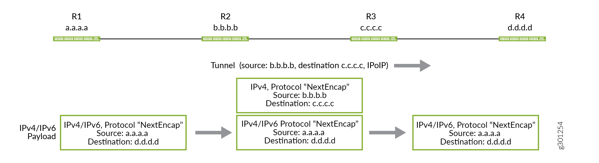
在此示例中,我们通过在 R2 和 R4 之间建立的 IP-over-IP 动态隧道交换从 R1 到 R5 的路由,反之亦然。通过使用协议 IS-IS,来自 R1 的路由导出到 R2,来自 R5 的路由导出到 R4。我们配置一个从 R2 到 R4 的单播 IPIP 隧道 Tunnel-01 ,以及另一个从 R4 到 R2 的隧道 Tunnel-01 。从对等设备的已配置目标网络的网络掩码内生成的路由前缀用于创建隧道,并且流量流向与隧道中的路由方向相反。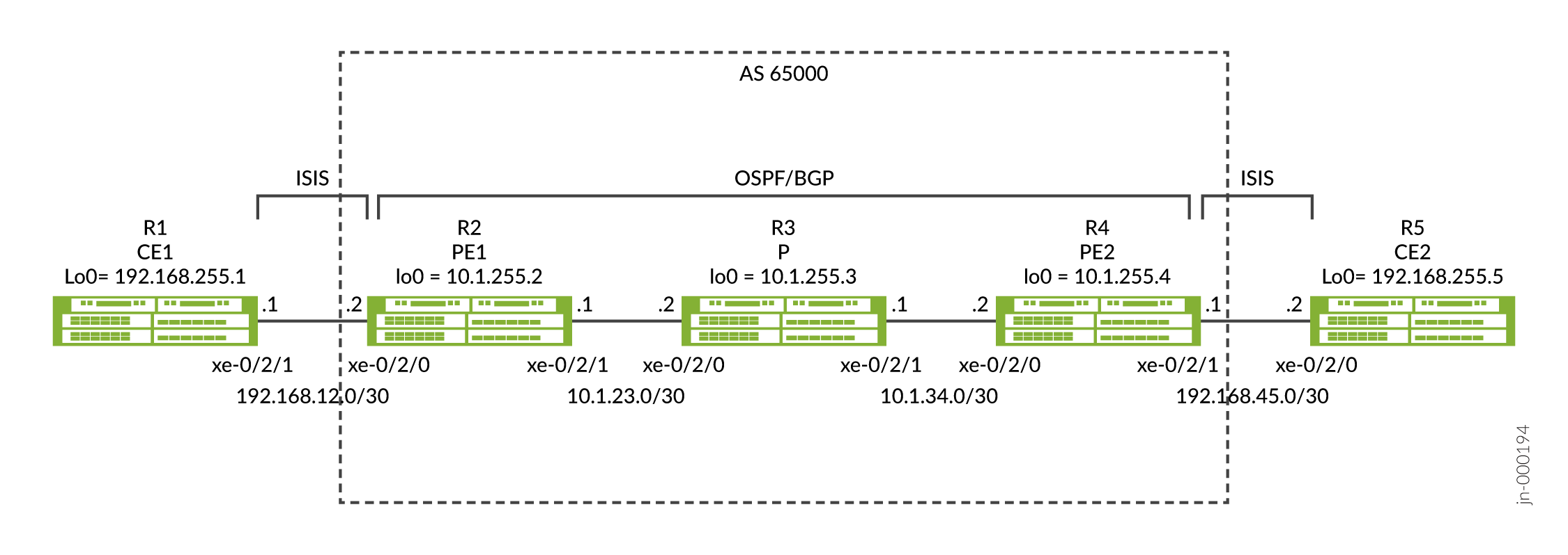
使用协议下一跃点配置 IP-over-IP 动态隧道
CLI 快速配置
要快速配置此示例,请复制以下命令,将其粘贴到文本文件中,删除所有换行符,更改与您的网络配置匹配所需的任何详细信息,将命令复制并粘贴到层次结构级别的 CLI [edit] 中,然后从配置模式进入提交。
R1
set interfaces xe-0/2/0 unit 0 description R1-to-R2
set interfaces xe-0/2/0 unit 0 family inet address 192.168.12.1/30
set interfaces xe-0/2/0 unit 0 family iso
set interfaces lo0 unit 0 family inet address 192.168.255.1/32
set interfaces lo0 unit 0 family iso address 49.0001.1920.1682.5501.00
set routing-options router-id 192.168.255.1
set protocols isis interface xe-0/2/0.0
set protocols isis interface lo0.0
set protocols isis level 1 disable
R2
set interfaces xe-0/2/0 description R2-to-R1
set interfaces xe-0/2/0 unit 0 family inet address 192.168.12.2/30
set interfaces xe-0/2/0 unit 0 family iso
set interfaces xe-0/2/1 description R2-to-R3
set interfaces xe-0/2/1 unit 0 family inet address 10.1.23.1/30
set interfaces lo0 unit 0 family inet address 10.1.255.2/32
set interfaces lo0 unit 0 family iso address 49.0001.0010.1255.0002.00
set policy-options policy-statement export-bgp term t1 from protocol bgp
set policy-options policy-statement export-bgp term t1 then accept
set policy-options policy-statement export-isis term t1 from protocol isis
set policy-options policy-statement export-isis term t1 then next-hop self
set policy-options policy-statement export-isis term t1 then accept
set routing-options resolution rib inet.0 resolution-ribs inet.3
set routing-options router-id 10.1.255.2
set routing-options autonomous-system 65000
set routing-options dynamic-tunnels Tunnel-01 source-address 10.1.255.2
set routing-options dynamic-tunnels Tunnel-01 ipip
set routing-options dynamic-tunnels Tunnel-01 destination-networks 10.1.255.0/24
set protocols bgp group iBGP type internal
set protocols bgp group iBGP local-address 10.1.255.2
set protocols bgp group iBGP family inet unicast
set protocols bgp group iBGP export export-isis
set protocols bgp group iBGP neighbor 10.1.255.4
set protocols isis interface xe-0/2/0.0
set protocols isis interface lo0.0
set protocols isis level 1 disable
set protocols isis export export-bgp
set protocols ospf area 0.0.0.0 interface xe-0/2/1.0
set protocols ospf area 0.0.0.0 interface lo0.0
R3
set interfaces xe-0/2/0 unit 0 description R3-to-R2
set interfaces xe-0/2/0 unit 0 family inet address 10.1.23.2/30
set interfaces xe-0/2/1 unit 0 description R3-to-R4
set interfaces xe-0/2/1 unit 0 family inet address 10.1.34.1/30
set interfaces lo0 unit 0 family inet address 10.1.255.3/32
set routing-options router-id 10.1.255.3
set protocols ospf area 0.0.0.0 interface xe-0/2/0.0
set protocols ospf area 0.0.0.0 interface xe-0/2/1.0
set protocols ospf area 0.0.0.0 interface lo0.0 passive
R4
set interfaces xe-0/2/0 unit 0 description R4-to-R3
set interfaces xe-0/2/0 unit 0 family inet address 10.1.34.2/30
set interfaces xe-0/2/1 unit 0 description R4-to-R5
set interfaces xe-0/2/1 unit 0 family inet address 192.168.45.1/30
set interfaces xe-0/2/1 unit 0 family iso
set interfaces lo0 unit 0 family inet address 10.1.255.4/32
set interfaces lo0 unit 0 family iso address 49.0001.0010.1255.0004.00
set policy-options policy-statement export-bgp term t1 from protocol bgp
set policy-options policy-statement export-bgp term t1 then accept
set policy-options policy-statement export-isis term t1 from protocol isis
set policy-options policy-statement export-isis term t1 then next-hop self
set policy-options policy-statement export-isis term t1 then accept
set routing-options resolution rib inet.0 resolution-ribs inet.3
set routing-options router-id 10.1.255.4
set routing-options autonomous-system 65000
set routing-options dynamic-tunnels Tunnel-01 source-address 10.1.255.4
set routing-options dynamic-tunnels Tunnel-01 ipip
set routing-options dynamic-tunnels Tunnel-01 destination-networks 10.1.255.0/24
set protocols bgp group iBGP type internal
set protocols bgp group iBGP local-address 10.1.255.4
set protocols bgp group iBGP family inet unicast
set protocols bgp group iBGP export export-isis
set protocols bgp group iBGP neighbor 10.1.255.2
set protocols isis interface xe-0/2/1.0
set protocols isis interface lo0.0
set protocols isis level 1 disable
set protocols isis export export-bgp
set protocols ospf area 0.0.0.0 interface xe-0/2/0.0
set protocols ospf area 0.0.0.0 interface lo0.0
R5
set interfaces xe-0/2/0 unit 0 description R5-to-R4
set interfaces xe-0/2/0 unit 0 family inet address 192.168.45.2/30
set interfaces xe-0/2/0 unit 0 family iso
set interfaces lo0 unit 0 family inet address 192.168.255.5/32
set interfaces lo0 unit 0 family iso address 49.0001.1920.1682.5505.00
set routing-options router-id 192.168.255.5
set protocols isis interface xe-0/2/0.0
set protocols isis interface lo0.0
set protocols isis level 1 disable
使用协议下一跃点配置 IP-IP 动态隧道
R1 的分步过程
R1 和 R5 具有类似的配置,因此我们仅显示 R1 的分步过程。
-
在 R1 上进入配置模式。
-
配置连接到 R2 和接口 lo0 的接口。确保同时配置系列
inet和iso. 协议 IS-IS 需要家族iso。[edit] user@R1# set interfaces xe-0/2/0 unit 0 description R1-to-R2 user@R1# set interfaces xe-0/2/0 unit 0 family inet address 192.168.12.1/30 user@R1# set interfaces xe-0/2/0 unit 0 family iso user@R1# set interfaces lo0 unit 0 family inet address 192.168.255.1/32 user@R1# set interfaces lo0 unit 0 family iso address 49.0001.1920.1682.5501.00
-
配置路由器 ID。
[edit]
user@R1# set routing-options router-id 192.168.255.1
-
配置协议 IS-IS。使用 IS-IS 协议在 R1 和 R2 之间通告路由。
[edit]
user@R1# set protocols isis interface xe-0/2/0.0
user@R1# set protocols isis interface lo0.0
user@R1# set protocols isis level 1 disable
-
从配置模式进入
commitR1。
R2 的分步过程
R2 和 R4 具有类似的配置,因此我们仅显示 R2 的分步过程。
-
在 R2 上进入配置模式。
-
配置连接到 R1 和 R3 以及接口 lo0 的接口。确保同时配置家族
inet和iso连接到 R1 和 lo0 的接口。[edit] user@R2# set interfaces xe-0/2/0 description R2-to-R1 user@R2# set interfaces xe-0/2/0 unit 0 family inet address 192.168.12.2/30 user@R2# set interfaces xe-0/2/0 unit 0 family iso user@R2# set interfaces xe-0/2/1 description R2-to-R3 user@R2# set interfaces xe-0/2/1 unit 0 family inet address 10.1.23.1/30 user@R2# set interfaces lo0 unit 0 family inet address 10.1.255.2/32 user@R2# set interfaces lo0 unit 0 family iso address 49.0001.0010.1255.0002.00
-
为连接到 R1 的接口配置协议 IS-IS。用于将 BGP 路由播发到 IS-IS 的导出策略显示在策略配置步骤中。
[edit]
user@R2# set protocols isis interface xe-0/2/0.0
user@R2# set protocols isis interface lo0.0
user@R2# set protocols isis level 1 disable
user@R2# set protocols isis export export-bgp
-
为 lo0 可访问性连接到 R3 的接口配置 OSPF 协议。
[edit]
user@R2# set protocols ospf area 0.0.0.0 interface xe-0/2/1.0
user@R2# set protocols ospf area 0.0.0.0 interface lo0.0
-
router-id在 R2 和 R4 之间配置 和autonomous-system、 和 IBGP。用于将 IS-IS 路由播发到 BGP 的导出策略显示在策略配置步骤中。[edit] user@R2# set routing-options router-id 10.1.255.2 user@R2# set routing-options autonomous-system 65000 user@R2# set protocols bgp group iBGP type internal user@R2# set protocols bgp group iBGP local-address 10.1.255.2 user@R2# set protocols bgp group iBGP family inet unicast user@R2# set protocols bgp group iBGP export export-isis user@R2# set protocols bgp group iBGP neighbor 10.1.255.4
-
配置在前面的步骤中应用的 BGP 和 IS-IS 导出策略。该
export-bgp策略作为导出应用于协议 IS-IS,以将 BGP 路由播发到 IS-ISexport-isis,并将策略作为导出应用于 BGP,以将 IS-IS 路由播发到 BGP。下一跃点自选选项允许 R2 将 IS-IS 路由播发到 BGP 中,并将 R2 作为下一跃点,而不是 R1 的接口下一跃点。[edit] user@R2# set policy-options policy-statement export-bgp term t1 from protocol bgp user@R2# set policy-options policy-statement export-bgp term t1 then accept user@R2# set policy-options policy-statement export-isis term t1 from protocol isis user@R2# set policy-options policy-statement export-isis term t1 then next-hop self user@R2# set policy-options policy-statement export-isis term t1 then accept
-
配置从 R2 到 R4 的 IP-IP 动态隧道 Tunnel-01 。配置选项
resolution-ribs inet.3允许在 inet.3 中进行路由解析,并且是建立隧道所必需的。[edit] user@R2# set routing-options resolution rib inet.0 resolution-ribs inet.3 user@R2# set routing-options dynamic-tunnels Tunnel-01 source-address 10.1.255.2 user@R2# set routing-options dynamic-tunnels Tunnel-01 ipip user@R2# set routing-options dynamic-tunnels Tunnel-01 destination-networks 10.1.255.0/24
-
(可选)- 从 R2 到 R4 的 IP-IP 动态隧道 Tunnel-01 的替代配置。您可以配置低于通往隧道端点的路由的协议下一跃点首选项的隧道首选项,而不是配置 。
resolution-ribs inet.3R4 的路由是使用 OSPF 获知的,优先级为 10,隧道的默认优先级为 305。配置低于 OSPF 优先级允许首选和建立隧道的隧道首选项。[edit] user@R2# set routing-options dynamic-tunnels Tunnel-01 source-address 10.1.255.2 user@R2# set routing-options dynamic-tunnels Tunnel-01 ipip user@R2# set routing-options dynamic-tunnels Tunnel-01 destination-networks 10.1.255.0/24 preference 9
-
从 R2 上的配置模式输入
commit。
R3 的分步过程
-
在 R3 上进入配置模式。
-
配置连接到 R2 和 R4 以及接口 lo0 的接口。
[edit]
user@R3# set interfaces xe-0/2/0 unit 0 description R3-to-R2
user@R3# set interfaces xe-0/2/0 unit 0 family inet address 10.1.23.2/30
user@R3# set interfaces xe-0/2/1 unit 0 description R3-to-R4
user@R3# set interfaces xe-0/2/1 unit 0 family inet address 10.1.34.1/30
user@R3# set interfaces lo0 unit 0 family inet address 10.1.255.3/32
-
配置路由器 ID。
[edit]
user@R3# set routing-options router-id 10.1.255.3
-
为 lo0 和 R4 连接的接口配置 OSPF 协议。
[edit]
user@R3# set protocols ospf area 0.0.0.0 interface xe-0/2/0.0
user@R3# set protocols ospf area 0.0.0.0 interface xe-0/2/1.0
user@R3# set protocols ospf area 0.0.0.0 interface lo0.0 passive
-
从 R3 设备上的配置模式输入
commit。
结果
通过从设备检查以下配置来验证您的配置,如下所示:
下面介绍了如何验证 R2 上的配置:
user@R2# show interfaces
xe-0/2/0 {
    description R2-to-R1;
    unit 0 {
        family inet {
            address 192.168.12.2/30;
        }
        family iso;
    }
}
xe-0/2/1 {
    description R2-to-R3;
    unit 0 {
        family inet {
            address 10.1.23.1/30;
        }
    }
}
lo0 {
    unit 0 {
        family inet {
            address 10.1.255.2/32;
        }
        family iso {
            address 49.0001.0010.1255.0002.00;
        }
    }
}
user@R2# show routing-options
resolution {
    rib inet.0 {
        resolution-ribs inet.3;
    }
}
router-id 10.1.255.2;
autonomous-system 65000;
dynamic-tunnels {
    Tunnel-01 {
        source-address 10.1.255.2;
        ipip;
        destination-networks {
            10.1.255.0/24;
        }
    }
}
user@R2# show protocols
bgp {
    group iBGP {
        type internal;
        local-address 10.1.255.2;
        family inet {
            unicast;
        }
        export export-isis;
        neighbor 10.1.255.4;
    }
}
isis {
    interface xe-0/2/0.0;
    interface lo0.0;
    level 1 disable;
    export export-bgp;
}
ospf {
    area 0.0.0.0 {
        interface xe-0/2/1.0;
        interface lo0.0;
    }
}
user@R2# show policy-options
policy-statement export-bgp {
    term t1 {
        from protocol bgp;
        then accept;
    }
}
policy-statement export-isis {
    term t1 {
        from protocol isis;
        then {
            next-hop self;
            accept;
        }
    }
}
验证
验证动态隧道数据库
目的
要验证动态隧道数据库信息,请使用 show dynamic-tunnels database 操作模式命令。
操作
user@R2> show dynamic-tunnels database
*- Signal Tunnels #- PFE-down
Table: inet.3

Destination-network: 10.1.255.0/24

Tunnel to: 10.1.255.4/32
  Reference count: 3
  Next-hop type: IPoIP (forwarding-nexthop)
    Source address: 10.1.255.2
    Next hop: tunnel-composite, 0x76b6c50, nhid 515
      Reference count: 2
      Ingress Route: [OSPF] 10.1.255.4/32, via metric 2
      Traffic Statistics: Packets 0, Bytes 0
      State: Up
  Aggregate Traffic Statistics:
    Tunnel Encapsulation: Dest 10.1.255.4, Src 10.1.255.2, IPoIP, Tunnel-Id 1
Traffic Statistics: Packets 0, Bytes 0 user@R4> show dynamic-tunnels database
*- Signal Tunnels #- PFE-down
Table: inet.3
Destination-network: 10.1.255.0/24
Tunnel to: 10.1.255.2/32
Reference count: 3
Next-hop type: IPoIP (forwarding-nexthop)
Source address: 10.1.255.4
Next hop: tunnel-composite, 0x76b6c50, nhid 513
Reference count: 2
Ingress Route: [OSPF] 10.1.255.2/32, via metric 2
Traffic Statistics: Packets 0, Bytes 0
State: Up
Aggregate Traffic Statistics:
Tunnel Encapsulation: Dest 10.1.255.2, Src 10.1.255.4, IPoIP, Tunnel-Id 1
Traffic Statistics: Packets 0, Bytes 0意义
输出指示在 R2(192.168.0.21 源)和 R4(192.168.0.41 目标)之间建立了一条 IPoIP 隧道,并在 R4(192.168.0.41 源)和 R2(192.168.0.21 目标)之间建立了另一条 IPoIP 隧道。
验证 inet.3 中的路由表
目的
要验证在 inet.3 表上生成的路由,请使用 show route table inet.3 操作模式命令。
操作
user@R2> show route table inet.3

inet.3: 2 destinations, 2 routes (2 active, 0 holddown, 0 hidden)
+ = Active Route, - = Last Active, * = Both

10.1.255.0/24      *[Tunnel/305] 02:02:44
                       Tunnel
10.1.255.4/32      *[Tunnel/305] 02:02:44, metric 2
Tunnel Composite, IPoIP (src 10.1.255.2 dest 10.1.255.4)user@R4> show route table inet.3
inet.3: 2 destinations, 2 routes (2 active, 0 holddown, 0 hidden)
+ = Active Route, - = Last Active, * = Both
10.1.255.0/24 *[Tunnel/305] 6d 01:35:50
Tunnel
10.1.255.2/32 *[Tunnel/305] 6d 01:35:48, metric 2
Tunnel Composite, IPoIP (src 10.1.255.4 dest 10.1.255.2)意义
输出指示用于解析将使用隧道的 BGP 流量的路由。
使用隧道验证 BGP 路由
目的
要验证在 R2 和 R4 上为 R1 和 R5 接收的 BGP 路由是否正在使用隧道。
操作
user@R2> show route protocol bgp

inet.0: 17 destinations, 17 routes (17 active, 0 holddown, 0 hidden)
+ = Active Route, - = Last Active, * = Both

192.168.255.5/32   *[BGP/170] 02:42:48, MED 10, localpref 100, from 10.1.255.4
                      AS path: I, validation-state: unverified
                    >  via Tunnel Composite, IPoIP (src 10.1.255.2 dest 10.1.255.4)

inet.3: 2 destinations, 2 routes (2 active, 0 holddown, 0 hidden)

iso.0: 1 destinations, 1 routes (1 active, 0 holddown, 0 hidden)

inet6.0: 1 destinations, 1 routes (1 active, 0 holddown, 0 hidden)user@R4> show route protocol bgp
inet.0: 17 destinations, 17 routes (17 active, 0 holddown, 0 hidden)
+ = Active Route, - = Last Active, * = Both
192.168.255.1/32 *[BGP/170] 00:13:30, MED 10, localpref 100, from 10.1.255.2
AS path: I, validation-state: unverified
> via Tunnel Composite, IPoIP (src 10.1.255.4 dest 10.1.255.2)
inet.3: 2 destinations, 2 routes (2 active, 0 holddown, 0 hidden)
iso.0: 1 destinations, 1 routes (1 active, 0 holddown, 0 hidden)
inet6.0: 1 destinations, 1 routes (1 active, 0 holddown, 0 hidden)意义
输出指示 R2 将隧道用于到 R5 的 BGP 路由,R4 正在使用隧道发送到 R1 的 BGP 路由。
验证端到端可访问性
目的
验证 R1 是否可以使用 ping 192.168.255.5 source 192.168.255.1 count 2 操作模式命令对 R5 执行 ping 操作。
操作
user@R1>ping 192.168.255.5 source 192.168.255.1 count 2
PING 192.168.255.5 (192.168.255.5): 56 data bytes
64 bytes from 192.168.255.5: icmp_seq=0 ttl=62 time=5.565 ms
64 bytes from 192.168.255.5: icmp_seq=1 ttl=62 time=5.957 ms

--- 192.168.255.5 ping statistics ---
2 packets transmitted, 2 packets received, 0% packet loss
round-trip min/avg/max/stddev = 5.565/5.761/5.957/0.196 ms
意义
R1 的输出显示 R1 可以 ping R5。
示例:使用 LDP 隧道在 MPLS 环境中配置 IPoIP 隧道,使用静态配置通过 inetcolor.0 解析
默认情况下,MPLS 的优先级高于 IP。例如,如果在 R2、R3 和 R4 之间配置 MPLS 和 LDP,其中 R4 可通过 LDP 到达 R2,则来自 R2 的路由将通过 LDP 解析,而不是 IP-over-IP,因为优先级更高。
如果您希望通过 IP-over-IP 而不是 LDP 解析特定路由,可以通过创建一个 inetcolor 表来实现,其中 IP-over-IP 具有更高的优先级,并将 BGP 设置为通过 inetcolor 表而不是 inet3 表解析该路由。以下示例演示如何使用静态配置执行此操作。
拓扑学
在此示例中,我们通过在 R2 和 R4 之间建立的 IP-over-IP 动态隧道交换从 R1 到 R5 的路由,反之亦然。通过使用协议 IS-IS,来自 R1 的路由导出到 R2,来自 R5 的路由导出到 R4。我们配置一个从 R2 到 R4 的单播 IPIP 隧道 Tunnel-01 ,以及另一个从 R4 到 R2 的隧道 Tunnel-01 。从对等设备的已配置目标网络在网络掩码内生成的路由前缀用于创建隧道,并且流量方向与隧道中的路由相反。
CLI 快速配置
R1
set interfaces xe-0/2/0 unit 0 description R1-to-R2
set interfaces xe-0/2/0 unit 0 family inet address 192.168.12.1/30
set interfaces xe-0/2/0 unit 0 family iso
set interfaces lo0 unit 0 family inet address 192.168.255.1/32
set interfaces lo0 unit 0 family iso address 49.0001.1920.1682.5501.00
set routing-options router-id 192.168.255.1
set protocols isis interface xe-0/2/0.0
set protocols isis interface lo0.0
set protocols isis level 1 disable
R2
set interfaces xe-0/2/0 description R2-to-R1
set interfaces xe-0/2/0 unit 0 family inet address 192.168.12.2/30
set interfaces xe-0/2/0 unit 0 family iso
set interfaces xe-0/2/1 description R2-to-R3
set interfaces xe-0/2/1 unit 0 family inet address 10.1.23.1/30
set interfaces xe-0/2/1 unit 0 family mpls
set interfaces lo0 unit 0 family inet address 10.1.255.2/32
set interfaces lo0 unit 0 family iso address 49.0001.0010.1255.0002.00
set policy-options policy-statement export-bgp term t1 from protocol bgp
set policy-options policy-statement export-bgp term t1 then accept
set policy-options policy-statement export-isis term t1 from protocol isis
set policy-options policy-statement export-isis term t1 then next-hop self
set policy-options policy-statement export-isis term t1 then accept
set policy-options policy-statement ipip-tunnel-color term term-01 from route-filter 192.168.255.5/32 exact
set policy-options policy-statement ipip-tunnel-color term term-01 then community add red
set policy-options policy-statement ipip-tunnel-color term term-01 then accept
set policy-options policy-statement set-dynamic-tunnel-ep term t1 from route-filter 10.1.255.4/32 exact
set policy-options policy-statement set-dynamic-tunnel-ep term t1 then tunnel-end-point-address 10.1.255.4
set policy-options policy-statement set-dynamic-tunnel-ep term t1 then accept
set policy-options community red members color:0:100
set routing-options router-id 10.1.255.2
set routing-options autonomous-system 65000
set routing-options dynamic-tunnels Tunnel-01 source-address 10.1.255.2
set routing-options dynamic-tunnels Tunnel-01 ipip
set routing-options dynamic-tunnels Tunnel-01 destination-networks 10.1.255.0/24 dyn-tunnel-attribute-policy set-dynamic-tunnel-ep
set routing-options dynamic-tunnels Tunnel-01 destination-networks 10.1.255.0/24 colors 100
set protocols bgp group iBGP type internal
set protocols bgp group iBGP local-address 10.1.255.2
set protocols bgp group iBGP import ipip-tunnel-color
set protocols bgp group iBGP family inet unicast extended-nexthop-color
set protocols bgp group iBGP export export-isis
set protocols bgp group iBGP neighbor 10.1.255.4
set protocols isis interface xe-0/2/0.0
set protocols isis interface lo0.0
set protocols isis level 1 disable
set protocols isis export export-bgp
set protocols ldp interface xe-0/2/1.0
set protocols mpls interface xe-0/2/1.0
set protocols ospf area 0.0.0.0 interface xe-0/2/1.0
set protocols ospf area 0.0.0.0 interface lo0.0
R3
set interfaces xe-0/2/0 unit 0 description R3-to-R2
set interfaces xe-0/2/0 unit 0 family inet address 10.1.23.2/30
set interfaces xe-0/2/0 unit 0 family mpls
set interfaces xe-0/2/1 unit 0 description R3-to-R4
set interfaces xe-0/2/1 unit 0 family inet address 10.1.34.1/30
set interfaces xe-0/2/1 unit 0 family mpls
set interfaces lo0 unit 0 family inet address 10.1.255.3/32
set routing-options router-id 10.1.255.3
set protocols ldp interface xe-0/2/0.0
set protocols ldp interface xe-0/2/1.0
set protocols mpls interface xe-0/2/0.0
set protocols mpls interface xe-0/2/1.0
set protocols ospf area 0.0.0.0 interface xe-0/2/0.0
set protocols ospf area 0.0.0.0 interface xe-0/2/1.0
set protocols ospf area 0.0.0.0 interface lo0.0 passive
R4
set interfaces xe-0/2/0 unit 0 description R4-to-R3
set interfaces xe-0/2/0 unit 0 family inet address 10.1.34.2/30
set interfaces xe-0/2/0 unit 0 family mpls
set interfaces xe-0/2/1 unit 0 description R4-to-R5
set interfaces xe-0/2/1 unit 0 family inet address 192.168.45.1/30
set interfaces xe-0/2/1 unit 0 family iso
set interfaces lo0 unit 0 family inet address 10.1.255.4/32
set interfaces lo0 unit 0 family iso address 49.0001.0010.1255.0004.00
set policy-options policy-statement export-bgp term t1 from protocol bgp
set policy-options policy-statement export-bgp term t1 then accept
set policy-options policy-statement export-isis term t1 from protocol isis
set policy-options policy-statement export-isis term t1 then next-hop self
set policy-options policy-statement export-isis term t1 then accept
set policy-options policy-statement ipip-tunnel-color term term-01 from route-filter 192.168.255.1/32 exact
set policy-options policy-statement ipip-tunnel-color term term-01 then community add red
set policy-options policy-statement ipip-tunnel-color term term-01 then accept
set policy-options policy-statement set-dynamic-tunnel-ep term t1 from route-filter 10.1.255.2/32 exact
set policy-options policy-statement set-dynamic-tunnel-ep term t1 then tunnel-end-point-address 10.1.255.2
set policy-options policy-statement set-dynamic-tunnel-ep term t1 then accept
set policy-options community red members color:0:100
set routing-options router-id 10.1.255.4
set routing-options autonomous-system 65000
set routing-options dynamic-tunnels Tunnel-01 source-address 10.1.255.4
set routing-options dynamic-tunnels Tunnel-01 ipip
set routing-options dynamic-tunnels Tunnel-01 destination-networks 10.1.255.0/24 dyn-tunnel-attribute-policy set-dynamic-tunnel-ep
set routing-options dynamic-tunnels Tunnel-01 destination-networks 10.1.255.0/24 colors 100
set protocols bgp group iBGP type internal
set protocols bgp group iBGP local-address 10.1.255.4
set protocols bgp group iBGP import ipip-tunnel-color
set protocols bgp group iBGP family inet unicast extended-nexthop-color
set protocols bgp group iBGP export export-isis
set protocols bgp group iBGP neighbor 10.1.255.2
set protocols isis interface xe-0/2/1.0
set protocols isis interface lo0.0
set protocols isis level 1 disable
set protocols isis export export-bgp
set protocols ldp interface xe-0/2/0.0
set protocols mpls interface xe-0/2/0.0
set protocols ospf area 0.0.0.0 interface xe-0/2/0.0
set protocols ospf area 0.0.0.0 interface lo0.0
R5
set interfaces xe-0/2/0 unit 0 description R5-to-R4
set interfaces xe-0/2/0 unit 0 family inet address 192.168.45.2/30
set interfaces xe-0/2/0 unit 0 family iso
set interfaces lo0 unit 0 family inet address 192.168.255.5/32
set interfaces lo0 unit 0 family iso address 49.0001.1920.1682.5505.00
set routing-options router-id 192.168.255.5
set protocols isis interface xe-0/2/0.0
set protocols isis interface lo0.0
set protocols isis level 1 disable
程序
R1 的分步过程
R1 和 R5 具有类似的配置,因此我们仅显示 R1 的分步过程。
-
在 R1 上进入配置模式。
-
配置连接到 R2 和接口 lo0 的接口。确保同时配置系列
inet和iso. 协议 IS-IS 需要家族iso。[edit] user@R1# set interfaces xe-0/2/0 unit 0 description R1-to-R2 user@R1# set interfaces xe-0/2/0 unit 0 family inet address 192.168.12.1/30 user@R1# set interfaces xe-0/2/0 unit 0 family iso user@R1# set interfaces lo0 unit 0 family inet address 192.168.255.1/32 user@R1# set interfaces lo0 unit 0 family iso address 49.0001.1920.1682.5501.00
-
配置路由器 ID。
[edit]
user@R1# set routing-options router-id 192.168.255.1
-
配置协议 IS-IS。使用 IS-IS 协议在 R1 和 R2 之间通告路由。
[edit]
user@R1# set protocols isis interface xe-0/2/0.0
user@R1# set protocols isis interface lo0.0
user@R1# set protocols isis level 1 disable
-
从配置模式进入
commitR1。
R2 的分步过程
R2 和 R4 具有类似的配置,因此我们仅显示 R2 的分步过程。
-
在 R2 上进入配置模式。
-
配置连接到 R1 和 R3 以及接口 lo0 的接口。确保同时配置家族
inet和连接到 R1 和 lo0 的接口,并同时配置家族inet和isompls连接到 R3 的接口。[edit] user@R2# set interfaces xe-0/2/0 description R2-to-R1 user@R2# set interfaces xe-0/2/0 unit 0 family inet address 192.168.12.2/30 user@R2# set interfaces xe-0/2/0 unit 0 family iso user@R2# set interfaces xe-0/2/1 description R2-to-R3 user@R2# set interfaces xe-0/2/1 unit 0 family inet address 10.1.23.1/30 user@R2# set interfaces xe-0/2/0 unit 0 family mpls user@R2# set interfaces lo0 unit 0 family inet address 10.1.255.2/32 user@R2# set interfaces lo0 unit 0 family iso address 49.0001.0010.1255.0002.00
-
为连接到 R1 的接口配置协议 IS-IS。用于将 BGP 路由播发到 IS-IS 的导出策略显示在策略配置步骤中。
[edit]
user@R2# set protocols isis interface xe-0/2/0.0
user@R2# set protocols isis interface lo0.0
user@R2# set protocols isis level 1 disable
user@R2# set protocols isis export export-bgp
-
为 lo0 可访问性连接到 R3 的接口配置 OSPF 协议。
[edit]
user@R2# set protocols ospf area 0.0.0.0 interface xe-0/2/1.0
user@R2# set protocols ospf area 0.0.0.0 interface lo0.0
-
为连接到 R3 的接口配置 LDP 和 MPLS 协议。
[edit]
user@R2# set protocols ldp interface xe-0/2/1.0
user@R2# set protocols mpls interface xe-0/2/1.0
-
在层次结构下
routing-options配置 和router-idautonomous-system,并在 R2 和 R4 之间配置 IBGP。策略配置步骤中显示了将社区添加到使用 BGP 获知的路由的导入策略,以及将 IS-IS 路由播发到 BGP 中的导出策略。extended-nexthop-color确保在配置中包含family inet unicast选项以允许使用 inetcolor.0 表进行解析。[edit] user@R2# set routing-options router-id 10.1.255.2 user@R2# set routing-options autonomous-system 65000 user@R2# set protocols bgp group iBGP type internal user@R2# set protocols bgp group iBGP local-address 10.1.255.2 user@R2# set protocols bgp group iBGP import ipip-tunnel-color user@R2# set protocols bgp group iBGP family inet unicast extended-nexthop-color user@R2# set protocols bgp group iBGP export export-isis user@R2# set protocols bgp group iBGP neighbor 10.1.255.4
-
配置从 R2 到 R4 的 IP-IP 动态隧道 Tunnel-01 。
colors配置选项允许在 inetcolor.0 路由表中创建隧道。配置dyn-tunnel-attribute-policyset-dynamic-tunnel-ep 静态隧道端点。策略随策略配置步骤一起显示。[edit] user@R2# set routing-options dynamic-tunnels Tunnel-01 source-address 10.1.255.2 user@R2# set routing-options dynamic-tunnels Tunnel-01 ipip user@R2# set routing-options dynamic-tunnels Tunnel-01 destination-networks 10.1.255.0/24 dyn-tunnel-attribute-policy set-dynamic-tunnel-ep user@R2# set routing-options dynamic-tunnels Tunnel-01 destination-networks 10.1.255.0/24 colors 100
-
配置在前面的配置步骤中应用的策略。该策略将 export-bgp BGP 路由播发到 IS-IS 中。该策略将 export-isis IS-IS 路由播发到 BGP 中,并将下一跃点更改为 R2。该 ipip-tunnel-color 策略将社区应用于动态隧道配置中
colors匹配的路由。该 set-dynamic-tunnel-ep 策略将 R4 配置为隧道端点。[edit] user@R2# set policy-options policy-statement export-bgp term t1 from protocol bgp user@R2# set policy-options policy-statement export-bgp term t1 then accept user@R2# set policy-options policy-statement export-isis term t1 from protocol isis user@R2# set policy-options policy-statement export-isis term t1 then next-hop self user@R2# set policy-options policy-statement export-isis term t1 then accept user@R2# set policy-options policy-statement ipip-tunnel-color term term-01 from route-filter 192.168.255.5/32 exact user@R2# set policy-options policy-statement ipip-tunnel-color term term-01 then community add red user@R2# set policy-options policy-statement ipip-tunnel-color term term-01 then accept user@R2# set policy-options policy-statement set-dynamic-tunnel-ep term t1 from route-filter 10.1.255.4/32 exact user@R2# set policy-options policy-statement set-dynamic-tunnel-ep term t1 then tunnel-end-point-address 10.1.255.4 user@R2# set policy-options policy-statement set-dynamic-tunnel-ep term t1 then accept user@R2# set policy-options community red members color:0:100
-
从配置模式输入
commit。
R3 的分步过程
-
在 R3 上进入配置模式。
-
配置连接到 R2 和 R4 以及接口 lo0 的接口。确保同时配置家族
inet和mpls连接到 R2 和 R4 的接口。[edit] user@R3# set interfaces xe-0/2/0 unit 0 description R3-to-R2 user@R3# set interfaces xe-0/2/0 unit 0 family inet address 10.1.23.2/30 user@R3# set interfaces xe-0/2/0 unit 0 family mpls user@R3# set interfaces xe-0/2/1 unit 0 description R3-to-R4 user@R3# set interfaces xe-0/2/1 unit 0 family inet address 10.1.34.1/30 user@R3# set interfaces xe-0/2/1 unit 0 family mpls user@R3# set interfaces lo0 unit 0 family inet address 10.1.255.3/32
-
配置路由器 ID。
[edit]
user@R3# set routing-options router-id 10.1.255.3
-
为 lo0 和 R4 连接的接口配置 OSPF 协议。
[edit]
user@R3# set protocols ospf area 0.0.0.0 interface xe-0/2/0.0
user@R3# set protocols ospf area 0.0.0.0 interface xe-0/2/1.0
user@R3# set protocols ospf area 0.0.0.0 interface lo0.0 passive
-
为连接到 R2 和 R4 的接口配置 LDP 和 MPLS 协议。
[edit]
user@R2# set protocols ldp interface xe-0/2/0.0
user@R2# set protocols ldp interface xe-0/2/1.0
user@R2# set protocols mpls interface xe-0/2/0.0
user@R2# set protocols mpls interface xe-0/2/1.0
-
从 R3 设备上的配置模式输入
commit。
结果
通过从设备检查以下配置来验证您的配置。
以下是检查 R2 上的配置的方法:
user@R2# show interfaces
xe-0/2/0 {
    description R2-to-R1;
    unit 0 {
        family inet {
            address 192.168.12.2/30;
        }
        family iso;
    }
}
xe-0/2/1 {
    description R2-to-R3;
    unit 0 {
        family inet {
            address 10.1.23.1/30;
        }
        family mpls;
    }
}
lo0 {
    apply-groups-except global;
    unit 0 {
        family inet {
            address 10.1.255.2/32;
        }
        family iso {
            address 49.0001.0010.1255.0002.00;
        }
    }
}
user@R2# show protocols
bgp {
    group iBGP {
        type internal;
        local-address 10.1.255.2;
        import ipip-tunnel-color;
        family inet {
            unicast {
                extended-nexthop-color;
            }
        }
        export export-isis;
        neighbor 10.1.255.4;
    }
}
isis {
    interface xe-0/2/0.0;
    interface lo0.0;
    level 1 disable;
    export export-bgp;
}
ldp {
    interface xe-0/2/1.0;
}
mpls {
    interface xe-0/2/1.0;
}
ospf {
    area 0.0.0.0 {
        interface xe-0/2/1.0;
        interface lo0.0;
    }
}
user@R2#show routing-options
router-id 10.1.255.2;
autonomous-system 65000;
dynamic-tunnels {
    Tunnel-01 {
        source-address 10.1.255.2;
        ipip;
        destination-networks {
            10.1.255.0/24 {
                dyn-tunnel-attribute-policy set-dynamic-tunnel-ep;
                colors 100;
            }
        }
    }
}
user@R2#show policy-options
policy-statement export-bgp {
    term t1 {
        from protocol bgp;
        then accept;
    }
}
policy-statement export-isis {
    term t1 {
        from protocol isis;
        then {
            next-hop self;
            accept;
        }
    }
}
policy-statement ipip-tunnel-color {
    term term-01 {
        from {
            route-filter 192.168.255.5/32 exact;
        }
        then {
            community add red;
            accept;
        }
    }
}
policy-statement set-dynamic-tunnel-ep {
    term t1 {
        from {
            route-filter 10.1.255.4/32 exact;
        }
        then {
            tunnel-end-point-address 10.1.255.4;
            accept;
        }
    }
}
community red members color:0:100;
验证
验证路由解析
目的
要验证 inet.3 和 inetcolor.0 表中路由的路由解析,请使用 show route table inet.3 和 show route table inetcolor.0 操作模式命令。
操作
user@R2> show route table inet.3

inet.3: 3 destinations, 4 routes (3 active, 0 holddown, 0 hidden)
+ = Active Route, - = Last Active, * = Both

10.1.255.0/24      *[Tunnel/305] 00:12:21
                       Tunnel
10.1.255.3/32      *[LDP/9] 1d 19:37:01, metric 1
                    >  to 10.1.23.2 via xe-0/2/1.0
10.1.255.4/32      *[LDP/9] 1d 19:32:25, metric 1
                    >  to 10.1.23.2 via xe-0/2/1.0, Push 299792
                    [Tunnel/305] 00:13:38, metric 2
Tunnel Composite, IPoIP (src 10.1.255.2 dest 10.1.255.4)user@R2> show route table inetcolor.0
inetcolor.0: 2 destinations, 2 routes (2 active, 0 holddown, 0 hidden)
+ = Active Route, - = Last Active, * = Both
10.1.255.0-0<c>/24
*[Tunnel/305] 00:13:26
Tunnel
10.1.255.4-100<c>/64
*[Tunnel/305] 00:13:26, metric 2
Tunnel Composite, IPoIP (src 10.1.255.2 dest 10.1.255.4-100<c>)意义
R2 输出表明,在 inet.3 表上,由于 10.1.255.4 路由的优先级高于 IP-over-IP,因此 LDP 正在解析路由。另一方面,在新创建的 inetcolor.0 表中,路由 10.1.255.4 是通过附加的 <c> IP-over-IP 隧道解析的。
验证动态隧道数据库
目的
要验证由 inetcolor.0 表中的路由创建的 IP-over-IP 动态隧道,请使用 show dynamic-tunnels database terse 操作模式命令。
操作
user@R2>show dynamic-tunnels database terse
*- Signal Tunnels #- PFE-down
Table: inet.3

Destination-network: 10.1.255.0/24

*- Signal Tunnels #- PFE-down
Table: inetcolor.0

Destination-network: 10.1.255.0-0<c>/24
Destination                      Source          Next-hop                 Type       Status
10.1.255.4-100<c>/64             10.1.255.2      0x76b71cc nhid 592       IPoIP      Up (via metric 2, tunnel-endpoint 10.1.255.4)
意义
R2 输出指示路由 192.168.0.41 已创建基于下一跃点的动态隧道。
验证路由下一跃点
目的
要验证设置为通过 IP-over-IP 解析的路由的所有下一跃点,请使用 show route 192.168.255.5 extensive expanded-nh 操作模式命令。
操作
user@R2>show route 192.168.255.5 extensive expanded-nh

inet.0: 18 destinations, 18 routes (18 active, 0 holddown, 0 hidden)
192.168.255.5/32 (1 entry, 1 announced)
Installed-nexthop:
Indr Composite (0x76b7238) 10.1.255.4-100<c>
  Krt_cnh (0x6fb1928) Index:593
    Krt_inh (0x7164d3c) Index:1048575 PNH: 10.1.255.4-100<c>
      Tun-comp (0x76b71cc) Index:592 IPoIP src 10.1.255.2 dest 10.1.255.4-100<c> tunnel-endpoint 10.1.255.4
TSI:
KRT in-kernel 192.168.255.5/32 -> {composite(593)}
IS-IS level 2, LSP fragment 0
        *BGP    Preference: 170/-101
                Next hop type: Indirect, Next hop index: 0
                Address: 0x76b7238
                Next-hop reference count: 2
                Source: 10.1.255.4
                Next hop type: Tunnel Composite, Next hop index: 592
                Next hop: via Tunnel Composite, IPoIP (src 10.1.255.2 dest 10.1.255.4-100<c> tunnel-endpoint 10.1.255.4), selected
                Protocol next hop: 10.1.255.4-100<c>
                Composite next hop: 0x6fb1928 593 INH Session ID: 0
                Indirect next hop: 0x7164d3c 1048575 INH Session ID: 0
                State: <Active Int Ext>
                Local AS: 65000 Peer AS: 65000
                Age: 20:14      Metric: 10      Metric2: 2
                Validation State: unverified
                Task: BGP_65000.10.1.255.4
                Announcement bits (2): 0-KRT 5-IS-IS
                AS path: I
                Communities: color:0:100
                Accepted
                Localpref: 100
                Router ID: 10.1.255.4
                Route-nexthop:
                Indr (0x76b7238) 10.1.255.4-100<c>
                  Krt_cnh (0x6fb1928) Index:593
                    Krt_inh (0x7164d3c) Index:1048575
                      Tun-comp (0x76b71cc) Index:592
                Thread: junos-main
                Composite next hops: 1
                        Protocol next hop: 10.1.255.4-100<c> Metric: 2
                        Composite next hop: 0x6fb1928 593 INH Session ID: 0
                        Indirect next hop: 0x7164d3c 1048575 INH Session ID: 0
                        Indirect path forwarding next hops: 1
                                Next hop type: Tunnel Composite
                                Tunnel type: IPoIP, (forwarding-nexthop), Reference count: 2, nhid: 592
                                Destination address: 10.1.255.4-100<c>, Source address: 10.1.255.2
                                Tunnel endpoint: 10.1.255.4
                                10.1.255.4-100<c>/64 Originating RIB: inetcolor.0
                                  Metric: 2 Node path count: 1
                                  Forwarding nexthops: 1
                                        Next hop type: Tunnel Composite
                                        Tunnel type: IPoIP, (extended-attr), Reference count: 1, nhid: 0
                                        Destination address: 10.1.255.4-100<c>, Source address: 10.1.255.2
意义
R2 的输出显示路由的 192.168.255.5 展开下一跃点。由于 R2 是 MX 系列路由器,因此它会发送协议下一跃点和间接下一跃点。
验证端到端可访问性
目的
验证 R1 是否可以使用 ping 192.168.255.5 source 192.168.255.1 count 2 操作模式命令对 R5 执行 ping 操作。
操作
user@R1>ping 192.168.255.5 source 192.168.255.1 count 2
PING 192.168.255.5 (192.168.255.5): 56 data bytes
64 bytes from 192.168.255.5: icmp_seq=0 ttl=62 time=6.009 ms
64 bytes from 192.168.255.5: icmp_seq=1 ttl=62 time=5.398 ms

--- 192.168.255.5 ping statistics ---
2 packets transmitted, 2 packets received, 0% packet loss
round-trip min/avg/max/stddev = 5.398/5.704/6.009/0.306 ms
意义
R1 的输出显示 R1 可以 ping R5。
示例:在 MPLS 云中配置带有 LDP 隧道的 IPoIP 隧道,使用 BGP 信令通过 inetcolor.0 解析
在启用了 LDP 的 MPLS 环境中,BGP 路由通过 inet.3 表上的 LDP 解析,因为 MPLS 的优先级高于 IP。
如果您仍然希望在 MPLS 环境中通过 IP-over-IP 解析路由,则可以创建一个 inetcolor.0 表来实现,该表为 IP-over-IP 分配更高的优先级,并通过 IP-over-IP 解析所选路由。要使用 BGP 启用此功能,路由解析在隧道的远程终端设备上执行,并在远程设备上配置导出策略,通过 BGP 信令接收和通告路由。此示例演示如何使用 BGP 协议配置进行配置。
在此示例中,我们通过在 R2 和 R4 之间建立的 IP-over-IP 动态隧道交换从 R1 到 R5 的路由,反之亦然。通过使用协议 IS-IS,来自 R1 的路由导出到 R2,来自 R5 的路由导出到 R4。我们配置一个从 R2 到 R4 的单播 IPIP 隧道 Tunnel-01 ,以及另一个从 R4 到 R2 的隧道 Tunnel-01 。从对等设备的已配置目标网络在网络掩码内生成的路由前缀用于创建隧道,并且流量方向与隧道中的路由相反。
CLI 快速配置
R1
set interfaces xe-0/2/0 unit 0 description R1-to-R2
set interfaces xe-0/2/0 unit 0 family inet address 192.168.12.1/30
set interfaces xe-0/2/0 unit 0 family iso
set interfaces lo0 unit 0 family inet address 192.168.255.1/32
set interfaces lo0 unit 0 family iso address 49.0001.1920.1682.5501.00
set routing-options router-id 192.168.255.1
set protocols isis interface xe-0/2/0.0
set protocols isis interface lo0.0
set protocols isis level 1 disable
R2
set interfaces xe-0/2/0 description R2-to-R1
set interfaces xe-0/2/0 unit 0 family inet address 192.168.12.2/30
set interfaces xe-0/2/0 unit 0 family iso
set interfaces xe-0/2/1 description R2-to-R3
set interfaces xe-0/2/1 unit 0 family inet address 10.1.23.1/30
set interfaces xe-0/2/1 unit 0 family mpls
set interfaces lo0 unit 0 family inet address 10.1.255.2/32
set interfaces lo0 unit 0 family iso address 49.0001.0010.1255.0002.00
set policy-options policy-statement export-bgp term t1 from protocol bgp
set policy-options policy-statement export-bgp term t1 then accept
set policy-options policy-statement export-tunnel-route term t1 from route-filter 192.168.255.1/32 exact
set policy-options policy-statement export-tunnel-route term t1 then tunnel-attribute set tunnel-attr-01
set policy-options policy-statement export-tunnel-route term t1 then next-hop self
set policy-options policy-statement export-tunnel-route term t1 then accept
set policy-options tunnel-attribute tunnel-attr-01 tunnel-type ipip
set policy-options tunnel-attribute tunnel-attr-01 tunnel-color 100
set policy-options tunnel-attribute tunnel-attr-01 remote-end-point 10.1.255.4
set routing-options router-id 10.1.255.2
set routing-options autonomous-system 65000
set routing-options dynamic-tunnels Tunnel-01 source-address 10.1.255.2
set routing-options dynamic-tunnels Tunnel-01 bgp-signal
set routing-options dynamic-tunnels Tunnel-01 destination-networks 10.1.255.0/24 colors 100
set protocols bgp group iBGP type internal
set protocols bgp group iBGP local-address 10.1.255.2
set protocols bgp group iBGP family inet unicast extended-nexthop-tunnel
set protocols bgp group iBGP export export-tunnel-route
set protocols bgp group iBGP neighbor 10.1.255.4
set protocols isis interface xe-0/2/0.0
set protocols isis interface lo0.0
set protocols isis level 1 disable
set protocols isis export export-bgp
set protocols ldp interface xe-0/2/1.0
set protocols mpls interface xe-0/2/1.0
set protocols ospf area 0.0.0.0 interface xe-0/2/1.0
set protocols ospf area 0.0.0.0 interface lo0.0
R3
set interfaces xe-0/2/0 unit 0 description R3-to-R2
set interfaces xe-0/2/0 unit 0 family inet address 10.1.23.2/30
set interfaces xe-0/2/0 unit 0 family mpls
set interfaces xe-0/2/1 unit 0 description R3-to-R4
set interfaces xe-0/2/1 unit 0 family inet address 10.1.34.1/30
set interfaces xe-0/2/1 unit 0 family mpls
set interfaces lo0 unit 0 family inet address 10.1.255.3/32
set routing-options router-id 10.1.255.3
set protocols ldp interface xe-0/2/0.0
set protocols ldp interface xe-0/2/1.0
set protocols mpls interface xe-0/2/0.0
set protocols mpls interface xe-0/2/1.0
set protocols ospf area 0.0.0.0 interface xe-0/2/0.0
set protocols ospf area 0.0.0.0 interface xe-0/2/1.0
set protocols ospf area 0.0.0.0 interface lo0.0 passive
R4
set interfaces xe-0/2/0 unit 0 description R4-to-R3
set interfaces xe-0/2/0 unit 0 family inet address 10.1.34.2/30
set interfaces xe-0/2/0 unit 0 family mpls
set interfaces xe-0/2/1 unit 0 description R4-to-R5
set interfaces xe-0/2/1 unit 0 family inet address 192.168.45.1/30
set interfaces xe-0/2/1 unit 0 family iso
set interfaces lo0 unit 0 family inet address 10.1.255.4/32
set interfaces lo0 unit 0 family iso address 49.0001.0010.1255.0004.00
set policy-options policy-statement export-bgp term t1 from protocol bgp
set policy-options policy-statement export-bgp term t1 then accept
set policy-options policy-statement export-tunnel-route term t1 from route-filter 192.168.255.5/32 exact
set policy-options policy-statement export-tunnel-route term t1 then tunnel-attribute set tunnel-attr-01
set policy-options policy-statement export-tunnel-route term t1 then next-hop self
set policy-options policy-statement export-tunnel-route term t1 then accept
set policy-options tunnel-attribute tunnel-attr-01 tunnel-type ipip
set policy-options tunnel-attribute tunnel-attr-01 tunnel-color 100
set policy-options tunnel-attribute tunnel-attr-01 remote-end-point 10.1.255.2
set routing-options router-id 10.1.255.4
set routing-options autonomous-system 65000
set routing-options dynamic-tunnels Tunnel-01 source-address 10.1.255.4
set routing-options dynamic-tunnels Tunnel-01 bgp-signal
set routing-options dynamic-tunnels Tunnel-01 destination-networks 10.1.255.0/24 colors 100
set protocols bgp group iBGP type internal
set protocols bgp group iBGP local-address 10.1.255.4
set protocols bgp group iBGP family inet unicast extended-nexthop-tunnel
set protocols bgp group iBGP export export-tunnel-route
set protocols bgp group iBGP neighbor 10.1.255.2
set protocols isis interface xe-0/2/1.0
set protocols isis interface lo0.0
set protocols isis level 1 disable
set protocols isis export export-bgp
set protocols ldp interface xe-0/2/0.0
set protocols mpls interface xe-0/2/0.0
set protocols ospf area 0.0.0.0 interface xe-0/2/0.0
set protocols ospf area 0.0.0.0 interface lo0.0
R5
set interfaces xe-0/2/0 unit 0 description R5-to-R4
set interfaces xe-0/2/0 unit 0 family inet address 192.168.45.2/30
set interfaces xe-0/2/0 unit 0 family iso
set interfaces lo0 unit 0 family inet address 192.168.255.5/32
set interfaces lo0 unit 0 family iso address 49.0001.1920.1682.5505.00
set routing-options router-id 192.168.255.5
set protocols isis interface xe-0/2/0.0
set protocols isis interface lo0.0
set protocols isis level 1 disable
程序
R1 的分步过程
R1 和 R5 具有类似的配置,因此我们仅显示 R1 的分步过程。
-
在 R1 上进入配置模式。
-
配置连接到 R2 和接口 lo0 的接口。确保同时配置系列
inet和iso. 协议 IS-IS 需要家族iso。[edit] user@R1# set interfaces xe-0/2/0 unit 0 description R1-to-R2 user@R1# set interfaces xe-0/2/0 unit 0 family inet address 192.168.12.1/30 user@R1# set interfaces xe-0/2/0 unit 0 family iso user@R1# set interfaces lo0 unit 0 family inet address 192.168.255.1/32 user@R1# set interfaces lo0 unit 0 family iso address 49.0001.1920.1682.5501.00
-
配置路由器 ID。
[edit]
user@R1# set routing-options router-id 192.168.255.1
-
配置协议 IS-IS。使用 IS-IS 协议在 R1 和 R2 之间通告路由。
[edit]
user@R1# set protocols isis interface xe-0/2/0.0
user@R1# set protocols isis interface lo0.0
user@R1# set protocols isis level 1 disable
-
从配置模式进入
commitR1。
R2 的分步过程
R2 和 R4 具有类似的配置,因此我们仅显示 R2 的分步过程。
-
在 R2 上进入配置模式。
-
配置连接到 R1 和 R3 以及接口 lo0 的接口。确保同时配置家族
inet和连接到 R1 和 lo0 的接口,并同时配置家族inet和isompls连接到 R3 的接口。[edit] user@R2# set interfaces xe-0/2/0 description R2-to-R1 user@R2# set interfaces xe-0/2/0 unit 0 family inet address 192.168.12.2/30 user@R2# set interfaces xe-0/2/0 unit 0 family iso user@R2# set interfaces xe-0/2/1 description R2-to-R3 user@R2# set interfaces xe-0/2/1 unit 0 family inet address 10.1.23.1/30 user@R2# set interfaces xe-0/2/0 unit 0 family mpls user@R2# set interfaces lo0 unit 0 family inet address 10.1.255.2/32 user@R2# set interfaces lo0 unit 0 family iso address 49.0001.0010.1255.0002.00
-
为连接到 R1 的接口配置协议 IS-IS。用于将 BGP 路由播发到 IS-IS 的导出策略显示在策略配置步骤中。
[edit]
user@R2# set protocols isis interface xe-0/2/0.0
user@R2# set protocols isis interface lo0.0
user@R2# set protocols isis level 1 disable
user@R2# set protocols isis export export-bgp
-
为 lo0 可访问性连接到 R3 的接口配置 OSPF 协议。
[edit]
user@R2# set protocols ospf area 0.0.0.0 interface xe-0/2/1.0
user@R2# set protocols ospf area 0.0.0.0 interface lo0.0
-
为连接到 R3 的接口配置 LDP 和 MPLS 协议。
[edit]
user@R2# set protocols ldp interface xe-0/2/1.0
user@R2# set protocols mpls interface xe-0/2/1.0
-
在层次结构下
routing-options配置 和router-idautonomous-system,并在 R2 和 R4 之间配置 IBGP。策略配置步骤中显示了将社区添加到使用 BGP 获知的路由的导入策略,以及将 IS-IS 路由播发至 BGP 并设置隧道属性的导出策略。确保在配置中包含family inet unicast选项extended-nexthop-tunnel,以允许使用 inetcolor.0 表进行分辨率。[edit] user@R2# set routing-options router-id 10.1.255.2 user@R2# set routing-options autonomous-system 65000 user@R2# set protocols bgp group iBGP type internal user@R2# set protocols bgp group iBGP local-address 10.1.255.2 user@R2# set protocols bgp group iBGP family inet unicast extended-nexthop-tunnel user@R2# set protocols bgp group iBGP export export-tunnel-route user@R2# set protocols bgp group iBGP neighbor 10.1.255.4
-
在 R2 上配置路由选项以创建从 R2 到 R4 的隧道。该
bgp-signal选项启用由 BGP 发出的隧道创建信号。colors配置选项允许在 inetcolor.0 路由表中创建隧道。[edit] user@R2# set routing-options dynamic-tunnels Tunnel-01 source-address 10.1.255.2 user@R2# set routing-options dynamic-tunnels Tunnel-01 bgp-signal user@R2# set routing-options dynamic-tunnels Tunnel-01 destination-networks 10.1.255.0/24 colors 100
-
配置在前面的配置步骤中应用的策略。该策略将 export-bgp BGP 路由播发到 IS-IS 中。该 export-tunnel-route 策略使用 将
tunnel-attributeIS-IS 路由从 R1 播发到 BGP,并将下一跃点更改为 R2。在tunnel-attr-01tunnel-attribute动态隧道的配置中colors设置tunnel-type、隧道端点和匹配颜色。[edit] user@R2# set policy-options policy-statement export-bgp term t1 from protocol bgp user@R2# set policy-options policy-statement export-bgp term t1 then accept user@R2# set policy-options policy-statement export-tunnel-route term t1 from route-filter 192.168.255.1/32 exact user@R2# set policy-options policy-statement export-tunnel-route term t1 then tunnel-attribute set tunnel-attr-01 user@R2# set policy-options policy-statement export-tunnel-route term t1 then next-hop self user@R2# set policy-options policy-statement export-tunnel-route term t1 then accept user@R2# set policy-options tunnel-attribute tunnel-attr-01 tunnel-type ipip user@R2# set policy-options tunnel-attribute tunnel-attr-01 tunnel-color 100 user@R2# set policy-options tunnel-attribute tunnel-attr-01 remote-end-point 10.1.255.4
-
从配置模式输入
commit。
R3 的分步过程
-
在 R3 上进入配置模式。
-
配置连接到 R2 和 R4 以及接口 lo0 的接口。确保同时配置家族
inet和mpls连接到 R2 和 R4 的接口。[edit] user@R3# set interfaces xe-0/2/0 unit 0 description R3-to-R2 user@R3# set interfaces xe-0/2/0 unit 0 family inet address 10.1.23.2/30 user@R3# set interfaces xe-0/2/0 unit 0 family mpls user@R3# set interfaces xe-0/2/1 unit 0 description R3-to-R4 user@R3# set interfaces xe-0/2/1 unit 0 family inet address 10.1.34.1/30 user@R3# set interfaces xe-0/2/1 unit 0 family mpls user@R3# set interfaces lo0 unit 0 family inet address 10.1.255.3/32
-
配置路由器 ID。
[edit]
user@R3# set routing-options router-id 10.1.255.3
-
为 lo0 和 R4 连接的接口配置 OSPF 协议。
[edit]
user@R3# set protocols ospf area 0.0.0.0 interface xe-0/2/0.0
user@R3# set protocols ospf area 0.0.0.0 interface xe-0/2/1.0
user@R3# set protocols ospf area 0.0.0.0 interface lo0.0 passive
-
为连接到 R2 和 R4 的接口配置 LDP 和 MPLS 协议。
[edit]
user@R2# set protocols ldp interface xe-0/2/0.0
user@R2# set protocols ldp interface xe-0/2/1.0
user@R2# set protocols mpls interface xe-0/2/0.0
user@R2# set protocols mpls interface xe-0/2/1.0
-
从 R3 设备上的配置模式输入
commit。
结果
您可以使用配置模式下的以下 show 命令检查配置。
以下是检查 R2 设备上的配置的方法:
user@R2# show interfaces
xe-0/2/0 {
    description R2-to-R1;
    unit 0 {
        family inet {
            address 192.168.12.2/30;
        }
        family iso;
    }
}
xe-0/2/1 {
    description R2-to-R3;
    unit 0 {
        family inet {
            address 10.1.23.1/30;
        }
        family mpls;
    }
}
lo0 {
    apply-groups-except global;
    unit 0 {
        family inet {
            address 10.1.255.2/32;
        }
        family iso {
            address 49.0001.0010.1255.0002.00;
        }
    }
}
user@R2# show protocols
bgp {
    group iBGP {
        type internal;
        local-address 10.1.255.2;
        family inet {
            unicast {
                extended-nexthop-tunnel;
            }
        }
        export export-tunnel-route;
        neighbor 10.1.255.4;
    }
}
isis {
    interface xe-0/2/0.0;
    interface lo0.0;
    level 1 disable;
    export export-bgp;
}
ldp {
    interface xe-0/2/1.0;
}
mpls {
    interface xe-0/2/1.0;
}
ospf {
    area 0.0.0.0 {
        interface xe-0/2/1.0;
        interface lo0.0;
    }
}
user@R2# show routing-options
router-id 10.1.255.2;
autonomous-system 65000;
dynamic-tunnels {
    Tunnel-01 {
        source-address 10.1.255.2;
        bgp-signal;
        destination-networks {
            10.1.255.0/24 colors 100;
        }
    }
}
user@R2# show policy-options
policy-statement export-bgp {
    term t1 {
        from protocol bgp;
        then accept;
    }
}
policy-statement export-tunnel-route {
    term t1 {
        from {
            route-filter 192.168.255.1/32 exact;
        }
        then {
            tunnel-attribute set tunnel-attr-01;
            next-hop self;
            accept;
        }
    }
}
tunnel-attribute tunnel-attr-01 {
    tunnel-type ipip;
    tunnel-color 100;
    remote-end-point 10.1.255.4;
}
验证
验证 BGP 路由
目的
验证使用 BGP 协议发送的路由。
操作
R2
user@R2> show route protocol bgp

inet.0: 18 destinations, 18 routes (18 active, 0 holddown, 0 hidden)
+ = Active Route, - = Last Active, * = Both

192.168.255.5/32   *[BGP/170] 01:21:51, MED 10, localpref 100, from 10.1.255.4
                      AS path: I, validation-state: unverified
                    >  via Tunnel Composite, IPoIP (src 10.1.255.2 dest 10.1.255.4-100<c> tunnel-endpoint 10.1.255.2)

inet.3: 3 destinations, 3 routes (3 active, 0 holddown, 0 hidden)

iso.0: 1 destinations, 1 routes (1 active, 0 holddown, 0 hidden)

mpls.0: 7 destinations, 7 routes (7 active, 0 holddown, 0 hidden)

inet6.0: 1 destinations, 1 routes (1 active, 0 holddown, 0 hidden)

inetcolor.0: 2 destinations, 2 routes (2 active, 0 holddown, 0 hidden)
意义
输出显示来自 BGP 的路由。
验证收到的路由
目的
使用以下操作模式命令验证通过 BGP 接收的路由。
操作
R2
user@R2> show route receive-protocol bgp 10.1.255.4 192.168.255.5 extensive

inet.0: 18 destinations, 18 routes (18 active, 0 holddown, 0 hidden)
* 192.168.255.5/32 (1 entry, 1 announced)
     Accepted
     Nexthop: 10.1.255.4
     MED: 10
     Localpref: 100
     AS path: I
     Tunnel type: ipip, Tunnel color: 100, Remote end point: 10.1.255.2
意义
R2 输出指示设备上收到的路由。
验证动态隧道
目的
验证动态隧道是否已启动且已发出 BGP 信号。
操作
R2
user@R2> show dynamic-tunnels database
*- Signal Tunnels #- PFE-down
Table: inet.3

Destination-network: 10.1.255.0/24

*- Signal Tunnels #- PFE-down
Table: inetcolor.0

Destination-network: 10.1.255.0-0<c>/24

Tunnel to: 10.1.255.4-100<c>/64
  Reference count: 3
  Next-hop type: IPoIP (bgp-signalled forwarding-nexthop)     Tunnel-endpoint: 10.1.255.2
    Source address: 10.1.255.2
    Next hop: tunnel-composite, 0x76b7238, nhid 592
      Reference count: 2
      Ingress Route: [OSPF] 10.1.255.4/32, via metric 2
      Tunnel Endpoint Ingress Route: [Direct] 10.1.255.2/32
      Traffic Statistics: Packets 0, Bytes 0
      State: Up
  Aggregate Traffic Statistics:
    Tunnel Encapsulation: Dest 10.1.255.2, Src 10.1.255.2, IPoIP, Tunnel-Id 1
    Traffic Statistics: Packets 0, Bytes 0
意义
R2 输出指示隧道已启动且已发出 BGP 信号。
验证路由解析
目的
要验证 inetcolor.0 表中路由的路由解析,请使用 show route table inetcolor.0 操作模式命令。
操作
user@R2> show route table inetcolor.0

inetcolor.0: 2 destinations, 2 routes (2 active, 0 holddown, 0 hidden)
+ = Active Route, - = Last Active, * = Both

10.1.255.0-0<c>/24
                   *[Tunnel/305] 01:33:33
                       Tunnel
10.1.255.4-100<c>/64
                   *[Tunnel/305] 01:28:44, metric 2
                       Tunnel Composite, BGP-Signal (src 10.1.255.2 dest 10.1.255.4-100<c>)
意义
R2 输出指示通往 10.1.255.4 的隧道已发出 BGP 信号。
验证端到端可访问性
目的
验证 R1 是否可以使用 ping 192.168.255.5 source 192.168.255.1 count 2 操作模式命令对 R5 执行 ping 操作。
操作
user@R1>ping 192.168.255.5 source 192.168.255.1 count 2
PING 192.168.255.5 (192.168.255.5): 56 data bytes
64 bytes from 192.168.255.5: icmp_seq=0 ttl=63 time=2.784 ms
64 bytes from 192.168.255.5: icmp_seq=1 ttl=63 time=1.904 ms

--- 192.168.255.5 ping statistics ---
2 packets transmitted, 2 packets received, 0% packet loss
round-trip min/avg/max/stddev = 1.904/2.344/2.784/0.440 ms
意义
R1 的输出显示 R1 可以 ping R5。
变更历史表
是否支持某项功能取决于您使用的平台和版本。 使用 Feature Explorer 查看您使用的平台是否支持某项功能。