
MPLS 伪线配置
以太网伪线概述
从 Junos OS 14.1X53 版和 Junos OS 16.1 版开始,以太网伪线用于通过 MPLS 网络传输以太网或 802.3 协议数据单元 (PDU),使服务提供商能够在现有 MPLS 网络上提供仿真以太网服务。以太网或 802.3 PDU 封装在伪线中,以提供点对点以太网服务。对于点对点以太网服务,支持以下故障管理功能:
IEEE 802.3ah 操作、行政和管理 (OAM) 标准。您可以在以太网点对点直接链路或跨以太网中继器的链路上配置 IEEE 802.3ah OAM 链路故障管理。
以太网 OAM 链路故障管理可用于物理链路级故障检测和管理。它在 OSI 模型的数据链路层中使用了一个新的可选子层。以太网 OAM 可以在任何全双工点对点或仿真点对点以太网链路上实施。不需要系统范围的实施;OAM 可以部署在路由器的特定接口上。传输的以太网 OAM 消息或 OAM PDU 的标准长度、未标记以太网帧在 64-1518 字节范围内的正常帧长度限制内。
以太网连接故障管理 (CFM),用于监控两个路由器之间的物理链路。
使用连续性检查协议进行故障监控的连接保护。连续性检查协议是一种邻接方发现和运行状况检查协议,用于发现并维护 VLAN 或链路级别的邻接关系。
使用链路跟踪协议进行路径发现和故障验证的路径保护。与 IP traceroute 类似,链路跟踪协议通过源和目标之间的一个或多个桥接网络将路径映射到目标 MAC 地址。
示例:以太网伪线基本配置
要求
下面列出了此配置的硬件和软件要求。
一台 ACX 系列路由器
Junos OS 12.2 或更高版本
以太网伪线基本配置概述
此处显示的配置是具有以太网交叉连接的以太网伪线的基本配置,用于在 ACX 系列路由器上进行物理接口封装。此配置适用于一个提供商边缘路由器。要完成以太网伪线的配置,您需要在多协议标签交换 (MPLS) 网络中的另一台提供商边缘路由器上重复此配置。
配置以太网伪线
过程
CLI 快速配置
要快速配置此示例,请复制以下命令,将其粘贴到文本文件中,删除所有换行符,更改详细信息,以便与网络配置匹配,然后将命令复制并粘贴到 [edit] 层级的 CLI 中:
set interfaces ge-0/1/1 encapsulation ethernet-ccc
set interfaces ge-0/1/1 unit 0
set interfaces ge-0/2/0 unit 0 family inet address 20.1.1.2/24
set interfaces ge-0/2/0 unit 0 family mpls
set interfaces lo0 unit 0 family inet address 70.1.1.1/32
set protocols rsvp interface ge-0/2/0.0
set protocols mpls no-cspf
set protocols mpls label-switched-path PE1-to-PE2 to 40.1.1.1
set protocols mpls interface ge-0/2/0.0
set protocols ospf traffic-engineering
set protocols ospf area 0.0.0.0 interface ge-0/2/0.0
set protocols ospf area 0.0.0.0 interface lo0.0 passive
set protocols ldp interface ge-0/2/0.0
set protocols ldp interface lo0.0
set protocols l2circuit neighbor 40.1.1.1 interface ge-0/1/1.0 virtual-circuit-id 1
要为交叉连接逻辑接口封装配置带有 802.1Q 标记的以太网伪线,请在 [edit interfaces ge-0/1/1 unit 0 encapsulation] 层次结构级别添加该vlan-ccc语句,而非此示例中显示的ethernet-ccc语句。
分步程序
创建两个千兆以太网接口,在一个接口上设置封装模式,在另一个接口上设置 MPLS。创建环路 (
lo0) 接口:[edit] user@host# edit interfaces [edit interfaces] user@host# set ge-0/1/1 encapsulation ethernet-ccc user@host# set ge-0/1/1 unit 0 user@host# set ge-0/2/0 unit 0 family inet address 20.1.1.2/24 user@host# set ge-0/2/0 unit 0 family mpls user@host# set lo0 unit 0 family inet address 70.1.1.1/32
在配置了 MPLS 的接口上启用 MPLS 和 RSVP 协议—
ge-0/2/0.0:[edit] user@host# edit protocols [edit protocols] user@host# set rsvp interface ge-0/2/0.0 user@host# set mpls interface ge-0/2/0.0
配置 LDP。如果为伪线配置 RSVP,则还必须配置 LDP:
[edit protocols]
user@host# set protocols ldp interface ge-0/2/0.0
user@host# set protocols ldp interface lo0.0
配置点对点标签交换路径 (LSP) 并禁用受限路径 LSP 计算:
[edit protocols]
user@host# set mpls label-switched-path PE1-to-PE2 to 40.1.1.1
user@host# set mpls no-cspf
在 MPLS 接口
ge-0/2/0.0和环路 (lo0) 接口上配置 OSPF 并启用流量工程:[edit protocols] user@host# set ospf traffic-engineering user@host# set ospf area 0.0.0.0 interface ge-0/2/0.0 user@host# set ospf area 0.0.0.0 interface lo0.0 passive
为以太网伪线唯一标识第 2 层电路:
[edit protocols]
user@host#  set l2circuit neighbor 40.1.1.1 interface ge-0/1/1.0 virtual-circuit-id 1
结果
[edit]
user@host# show
interfaces {
    ge-0/1/1 {
        encapsulation ethernet-ccc;
        unit 0;
    }
    ge-0/2/0 {
        unit 0 {
            family inet {
                address 20.1.1.2/24;
            }
            family mpls;
        }
    }
    lo0 {
        unit 0 {
            family inet {
                address 70.1.1.1/32;
            }
        }
    }
}
protocols {
    rsvp {
        interface ge-0/2/0.0;
    }
    mpls {
        no-cspf;
        label-switched-path PE1-to-PE2 {
            to 40.1.1.1;
        }
        interface ge-0/2/0.0;
    }
    ospf {
        traffic-engineering;
        area 0.0.0.0 {
            interface ge-0/2/0.0;
            interface lo0.0 {
                passive;
            }
        }
    }
    ldp {
        interface ge-0/2/0.0;
        interface lo0.0;
    }
    l2circuit {
        neighbor 40.1.1.1 {
            interface ge-0/1/1.0 {
                virtual-circuit-id 1;
            }
        }
    }
}
ACX 系列通用城域网路由器伪线概述
伪线是一种第 2 层电路或服务,它通过 MPLS 分组交换网络模拟电信服务的基本属性,例如 T1 线路。伪线旨在仅提供最低限度的必要功能来模拟线路,并具有给定服务定义所需的忠实度。在 ACX 系列路由器上,支持以太网、异步传输模式 (ATM) 和时分多路复用 (TDM) 伪线。支持以下伪线功能:
伪线传输服务,通过 IP 和 MPLS 网络基础架构传输第 1 层和第 2 层信息。ACX 系列仅支持类似的端点,例如 T1 到 T1、ATM 到 ATM 和以太网到以太网。
冗余伪线备用 PE 路由器和客户边缘设备之间的连接,在发生某些类型的故障后维护第 2 层电路和服务。伪线冗余提高了某些网络类型网络(例如城域网)的可靠性,在这些网络中,单点故障可能会中断多个客户的服务。支持以下伪线冗余功能:
在发生某些类型的故障后,使用备用伪线维护第 2 层电路服务,备份 PE 路由器和客户边缘设备之间的连接。
如果发生故障,则为保护接口,用于备份主接口。只有在主接口正常运行时,网络流量才会使用主接口。如果主接口出现故障,流量将切换至保护接口。
热备用和冷备用,可快速切换到备用或备用伪线。
以太网连接故障管理 (CFM),可用于监控两个路由器之间的物理链路。仅支持以太网伪线的 CFM 的以下主要功能:
使用连续性检查协议进行故障监控的连接保护。连续性检查协议是一种邻接方发现和运行状况检查协议,用于发现并维护 VLAN 或链路级别的邻接关系。
使用链路跟踪协议进行路径发现和故障验证的路径保护。与 IP traceroute 类似,链路跟踪协议通过源和目标之间的一个或多个桥接网络将路径映射到目标 MAC 地址。
了解 FEC 129 的多段伪线
了解多段伪线
伪线是一种第 2 层电路或服务,可通过 MPLS 分组交换网络 (PSN) 模拟电信服务的基本属性,例如 T1 线路。伪线旨在仅提供最低限度的必要功能来模拟具有给定服务定义所需的弹性要求的线路。
当伪线在同一 PSN 的边缘上发起和终止时,始发和终止提供商边缘 (T-PE) 设备之间的伪线标签不变。这称为单段伪线 (SS-PW)。 图 1 展示了在两个 PE 路由器之间建立的 SS-PW。PE1 和 PE2 路由器之间的伪线位于同一自治系统 (AS) 内。
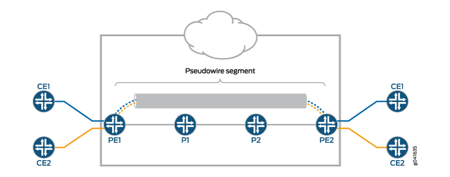
如果由于在两个 PE 之间建立单个控制平面不可行或不可取而无法建立从本地到远程 PE 的单个伪线,则使用多段伪线 (MS-PW)。
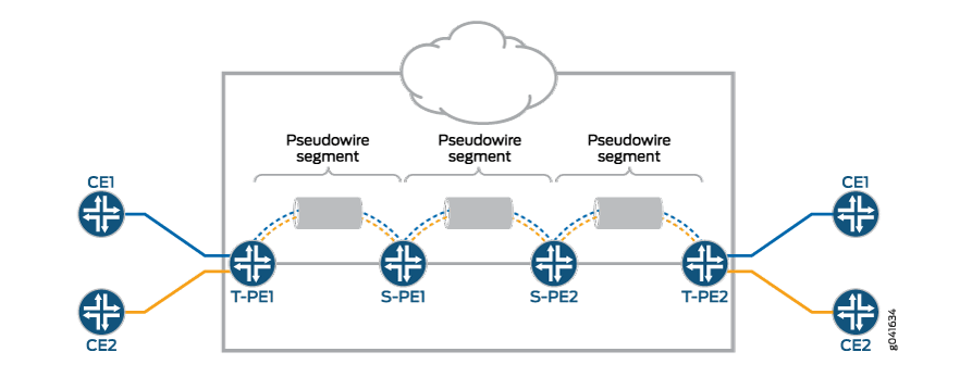
MS-PW 是一组两个或多个连续的 SS-PW,用作单个点对点伪线。它也被称为交换式伪线。MS-PW 可以跨越不同的区域或网域。区域可以被视为属于相同或不同管理域的内部网关协议 (IGP) 区域或 BGP 自治系统。MS-PW 跨越相同或不同运营商网络的多个核心或 AS。第 2 层 VPN MS-PW 最多可包含 254 个伪线段。
图 2 显示了一组作为单个伪线运行的两个或多个伪线段。终端路由器称为终端 PE (T-PE) 路由器,交换路由器称为交换 PE (S-PE) 路由器。S-PE 路由器终止 MS-PW 中前一个和后续伪线段的隧道。S-PE 路由器可以切换 MS-PW 前一个和后续伪线段的控制和数据平面。当所有单段伪线都开启时,MS-PW被声明为开启。
将 FEC 129 用于多段伪线
目前,FEC 129 定义了两种类型的连接电路标识符 (AII):
1 类 AII
2 类 AII
对 FEC 129 的 MS-PW 的支持使用 2 类 AII。根据 RFC 5003 的定义,2 类 AII 是全球唯一的。
在 MPLS PSN 上使用 FEC 129 的单段伪线 (SS-PW) 可以同时使用 1 类和 2 类 AII。对于使用 FEC 129 的 MS-PW,伪线本身被标识为一对端点。这要求伪线端点具有唯一的标识符。
对于动态放置的MS-PW,为了伪线的可访问性和可管理性,连接电路的标识符必须是全局唯一的。因此,单个全局唯一地址将分配给构成 MS-PW 的所有连接电路和 S-PE。
2 类 AII 由三个字段组成:
Global_ID — 全局标识,通常是AS编号。
前缀 — IPv4 地址,通常是路由器 ID。
AC_ID - 本地连接电路,这是用户可配置的值。
由于 2 类 AII 已包含 T-PE 的 IP 地址并且它是全局唯一的,因此从 FEC 129 伪线信令的角度来看,该组合(AGI、SAII、TAII)在所有互连伪线域中唯一标识 MS-PW。
建立多段伪线概述
通过动态自动选择预定义的 S-PE 并将 MS-PW 放置在两个 T-PE 设备之间来建立 MS-PW。
动态选择 S-PE 时,系统会使用 BGP 自动发现功能自动发现和选择每个 S-PE,而无需在所有 S-PE 上调配 FEC 129 伪线相关信息。BGP 用于在整个 PSN 中传播伪线地址信息。
由于 S-PE 上没有手册调配 FEC 129 伪线信息,因此附件组标识符 (AGI) 和附件单个标识符 (AII) 会自动重用,并且通过每个 T-PE 设备的主动和无源角色实现在正向和反向方向上为伪线选择同一组 S-PE。
活动 — T-PE 发起 LDP 标签映射消息。
被动 — T-PE 在收到由有源 T-PE 发起的标签映射消息之前,不会启动 LDP 标签映射消息。被动 T-PE 将其标签映射消息发送到接收源自其活动 T-PE 的标签映射消息的同一 S-PE。这可以确保在相反方向上使用同一组 S-PE。
多段伪线支持伪线状态
T-PE 上的伪线状态行为
以下伪线状态消息与 T-PE 相关:
0x00000010 — 面向本地 PSN 的伪线(出口)传输故障。
0x00000001 — 通用非转发故障代码。这被设置为本地故障代码。本地故障代码设置在本地 T-PE,LDP 向远程 T-PE 发送具有相同故障代码的伪线状态 TLV 消息。
故障代码是按位或进行的,并存储为远程伪线状态代码。
S-PE 上的伪线状态行为
S-PE 启动伪线状态消息,用于指示伪线故障。伪线通知消息中的 SP-PE 会提示故障起源的位置。
当 S-PE 检测到本地故障时,将沿伪线向两个方向发送伪线状态消息。由于 S-PE 上没有连接电路,因此只有以下状态消息相关:
0x00000008 — 本地面向 PSN 的伪线(入口)接收故障。
0x00000010 — 面向本地 PSN 的伪线(出口)传输故障。
为了指示哪个 SS-PW 有故障,LDP 通知消息中附加了一个 LDP SP-PE TLV 和伪线状态代码。控制平面切换功能将伪线状态从一个伪线传递到另一个伪线,保持不变。
如果 S-PE 发起具有一个特定伪线状态位的伪线状态通知消息,则对于 S-PE 收到的伪线状态代码,将在本地处理相同的位,直到清除 S-PE 的原始状态错误才会转发。
S-PE 仅为其涉及的每个 SS-PW 保留两个伪线状态代码 - 本地伪线状态代码和远程伪线状态代码。远程伪线状态代码的值是该段之前的SS-PW链中伪线状态代码的逻辑或操作的结果。每个 S-PE 在收到此状态代码时都会逐步更新此状态代码,并发送给下一个 S-PE。本地伪线状态根据其本地伪线状态在本地生成。
仅在 SP-PE 上检测到传输故障。当没有 MPLS LSP 到达下一个分段时,将检测本地传输故障。发送故障发送到下一个下游段,接收故障发送到上游段。
S-PE 上收到的远程故障将原封不动地沿着 MS-PW 传递。本地故障将发送到 S-PE 涉及的伪线的两个网段。
MS-PW支持伪线TLV
MS-PW 为 LDP SP-PE TLV [RFC 6073] 提供以下支持:
用于 MS-PW 的 LDP SP-PE TLV 包括:
本地 IP 地址
远程 IP 地址
SP-PE 会将 LDP SP-PE TLV 添加到标签映射消息中。每个 SP-PE 都会将本地 LDP SP-PE TLV 追加到从其他分段接收的 SP-PE 列表中。
在 SP-PE 上生成通知时,伪线状态通知消息包括 LDP SP-PE TLV。
支持和不支持的功能
Junos OS 通过 MS-PW 支持以下功能:
构建 MS-PW 的每个 SS-PW 的 MPLS PSN。
MS-PW 中的每个 SS-PW 采用相同的伪线封装 – 以太网或 VLAN-CCC。
通用 PWid FEC 与 T-LDP 作为端到端伪线信令协议,用于设置每个 SS-PW。
MP-BGP 用于自动发现与 MS-PW 关联的每个 SS-PW 的两个端点 PE。
标准 MPLS 操作可拼接两个并排的 SS-PW 以形成 MS-PW。
自动发现 S-PE,以便动态放置 MS-PW。
S-PE 的最低配置。
操作、管理和维护 (OAM) 机制,包括端到端 MPLS ping 或端到任意 S-PE MPLS ping、MPLS 路径追踪、端到端 VCCV 和双向转发检测 (BFD)。
用于 MS-PW 的伪线连接点 (SP) PE TLV。
MS-PW 上的复合下一跃点。
MS-PW的伪线状态TLV。
Junos OS 不支持以下 MS-PW 功能:
LDP FEC 128 和 LDP FEC 129 的混合物。
静态伪线,其中每个标签都以静态方式调配。
平滑路由引擎切换。
不间断主动路由。
多宿主。
OAM 中的部分连接验证(源自 S-PE)。
示例:配置多段伪线
此示例说明如何配置动态多段伪线 (MS-PW),其中拼接提供商边缘 (S-PE) 设备由 BGP 自动动态发现,伪线由 LDP 使用 FEC 129 发出信号。这种部署需要在 S-PE 上进行最低限度的配置,从而减轻与静态配置的第 2 层电路相关的配置负担,同时仍使用 LDP 作为底层信令协议。
要求
此示例使用以下硬件和软件组件:
六台路由器,可以是 M Series 多服务边缘路由器、MX 系列 5G 通用路由平台、T Series 核心路由器或 PTX 系列 数据包传输路由器 的组合。
两个远程 PE 设备配置为终止 PE (T-PE)。
两个 S-PE 配置为:
路由反射器(在区域间配置的情况下)。
如果采用 AS 间配置,则为 AS 边界路由器或路由反射器。
所有设备上运行 Junos OS 13.3 或更高版本。
开始之前:
配置设备接口。
配置 OSPF 或任何其他 IGP 协议。
配置 BGP。
配置 LDP。
配置 MPLS。
概述
从 Junos OS 13.3 版开始,您可以在 MPLS 数据包交换网络 (PSN) 中使用 FEC 129 以及 LDP 信令和 BGP 自动发现来配置 MS-PW。MS-PW 功能还提供来自 T-PE 设备的操作、行政和管理 (OAM) 功能,例如 ping、traceroute 和 BFD。
要在 MS-PW 中启用 S-PE 的自动发现,请在层次结构级别包含[edit protocols bgp group group-name family l2vpn]该auto-discovery-mspw语句。
family l2vpn {
    auto-discovery-mspw;
}
S-PE的自动选择和MS-PW的动态设置在很大程度上依赖于BGP。BGP为FEC 129伪线构造的用于自动发现S-PE的网络层可达性信息(NLRI)称为MS-PW NLRI [draft-ietf-pwe3-dynamic-ms-pw-15.txt]。MS-PW NLRI 本质上是一个前缀,由路由识别符 (RD) 和 FEC 129 源附件标识符 (SAII) 组成。它称为 BGP 自动发现 (BGP-AD) 路由,编码为 RD:SAII。
只有配置了 2 类 AII 的 T-PE 才会分别启动自己的 MS-PW NLRI。由于 2 类 AII 在全局范围内是唯一的,因此 MS-PW NLRI 用于识别调配 2 类 AII 的 PE 设备。1 类 AII 和 2 类 AII 之间的区别要求在 BGP 中定义新的地址族指示器 (AFI) 和后续地址族标识符 (SAFI),以支持 MS-PW。用于识别 MS-PW NLRI 的拟议 AFI 和 SAFI 值对分别为 25 和 6(等待 IANA 分配)。
AFI 和 SAFI 值支持 S-PE 的自动发现,应在发起路由的 T-PE 和参与信令的 S-PE 上配置。
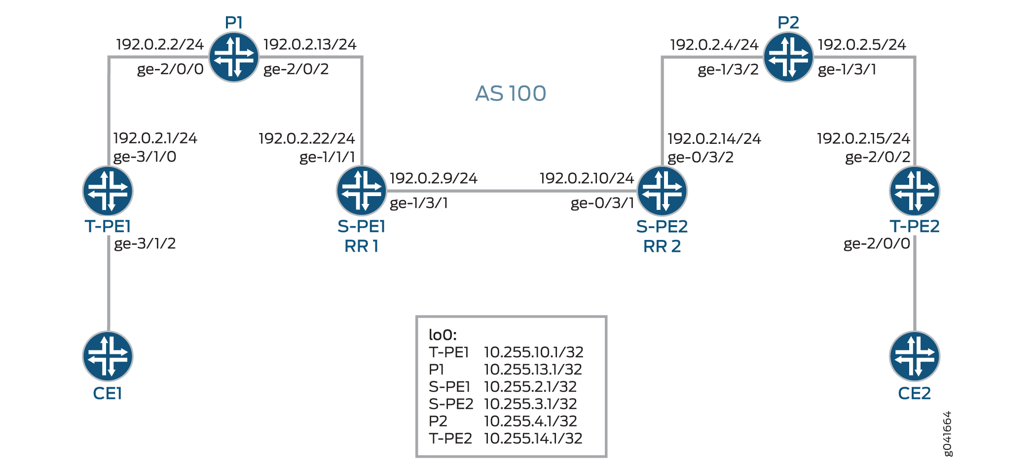
图 3 展示了两个远程 PE 路由器(T-PE1 和 T-PE2)之间的区域间 MS-PW 设置。提供商 (P) 路由器为 P1 和 P2,S-PE 路由器为 S-PE1 和 S-PE2。MS-PW 在 T-PE1 和 T-PE2 之间建立,所有设备都属于同一个 AS — AS 100。由于 S-PE1 和 S-PE2 属于同一个 AS,因此它们充当路由反射器,也分别称为 RR 1 和 RR 2。
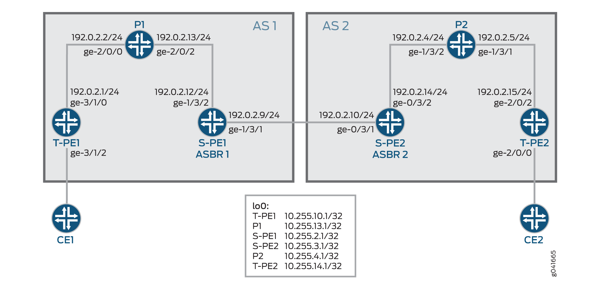
图 4 展示了 AS 间 MS-PW 设置。MS-PW 在 T-PE1 和 T-PE2 之间建立,其中 T-PE1、P1 和 S-PE1 属于 AS 1,S-PE2、P2 和 T-PE2 属于 AS 2。由于 S-PE1 和 S-PE2 属于不同的 AS,因此将其配置为 ASBR 路由器,并且分别称为 ASBR 1 和 ASBR 2。
以下部分将介绍如何在区域间和 AS 间场景中建立 MS-PW。
Minimum Configuration Requirements on S-PE
为了动态发现 SS-PW 的两端并动态设置 T-LDP 会话,需要满足以下条件:
对于区域间 MS-PW,每个 S-PE 都扮演 ABR 和 BGP 路由反射器角色。
在区域间情况下,如 图 3 所示,S-PE 扮演 BGP 路由反射器角色,并将 BGP-AD 路由反射到其客户端。一个 T-PE 播发的 BGP-AD 路由最终会到达其远程 T-PE。由于每个 S-PE 设置下一跳自,接收 BGP-AD 路由的 S-PE 或 T-PE 始终可以通过BGP下一跃点发现在其本地AS或本地区域播发 BGP-AD 的 S-PE。
对于 AS 间 MS-PW,每个 S-PE 要么扮演一个 ASBR 要么是一个 BGP 路由反射器角色。
在 MS-PW 中,两个 T-PE 分别启动 BGP-AD 路由。当 S-PE 通过与 T-PE 的 IBGP 会话或常规 BGP-RR 接收 BGP-AD 路由时,它会设置下一跃点自播,然后在 AS 间情况下将 BGP-AD 路由重新播发至其一个或多个 EBGP 对等方,如 图 4 所示。
当重新播发或反映 MS-PW 的 BGP-AD 路由时,每个 S-PE 都必须设置下一跳自。
Active and Passive Role of T-PE
为确保在两个方向上将同一组 S-PE 用于 MS-PW,两个 T-PE 在 FEC 129 信令方面发挥不同的作用。这是为了避免在为 MS-PW 动态选择每个 S-PE 时,T-PE1 和 T-PE2 选择不同的路径。
当使用 FEC 129 向 MS-PW 发出信号时,每个 T-PE 可以独立开始向 MS-PW 发出信号。信令过程可能会导致尝试通过不同的 S-PE 设置 MS-PW 的每个方向。
为避免这种情况,其中一个 T-PE 必须启动伪线信令(主动角色),而另一个 T-PE 则等待接收 LDP 标签映射,然后再发送相应的伪线 LDP 标签映射消息(被动角色)。当 MS-PW 路径动态放置时,必须先识别有源 T-PE(源 T-PE)和无源 T-PE(目标 T-PE),然后才能为给定 MS-PW 启动信令。根据 SAII 值确定哪个 T-PE 承担主动角色,其中具有较大 SAII 值的 T-PE 起积极作用。
在本例中,T-PE1 和 T-PE 2 的 SAII 值分别为 800:800:800 和 700:700:700。由于 T-PE1 的 SAII 值较高,因此它承担主动角色,T-PE2 承担被动角色。
Directions for Establishing an MS-PW
S-PE 用于设置 MS-PW 的说明是:
转发方向 — 从有源 T-PE 到无源 T-PE。
在此方向上,S-PE 执行 BGP-AD 路由查找,以确定要发送标签映射消息的下一跳 S-PE。
反向 — 从无源 T-PE 到有源 T-PE。
在此方向上,S-PE 不执行 BGP-AD 路由查找,因为标签映射消息是从 T-PE 接收的,并且拼接路由安装在 S-PE 中。
在此示例中,MS-PW 在从 T-PE1 到 T-PE2 的转发方向上建立。当 MS-PW 从 T-PE2 放置到 T-PE1 时,MS-PW 将以相反的方向建立。
Autodiscovery and Dynamic Selection of S-PE
在 BGP 中定义了新的 AFI 和 SAFI 值,以支持基于 2 类 AII 的 MS-PW。此新地址族支持 S-PE 的自动发现。必须同时在 TPE 和 SPE 上配置此地址族。
第 2 层 VPN 组件负责动态选择要沿着 MS-PW 在转发方向上的下一个 S-PE。
在转发方向上,选择下一个 S-PE 基于 BGP 播发的 BGP-AD 路由和 LDP 发送的伪线 FEC 信息。BGP-AD 路由由无源 T-PE (T-PE2) 反向启动,而伪线 FEC 信息由 LDP 从有源 T-PE (T-PE1) 转发方向发送。
在相反的方向上,通过查找用于在转发方向上建立伪线的 S-PE (S-PE1),获得下一个 S-PE (S-PE2) 或活动 T-PE (T-PE1)。
Provisioning a T-PE
要支持 FEC 129 2 类 AII,T-PE 需要配置其远程 T-PE 的 IP 地址、全局 ID 和连接电路 ID。 不支持在 T-PE 上显式指定要使用的一组 S-PE 的显式路径。这样就无需为每个 S-PE 配置一个 2 类 AII。
Stitching an MS-PW
S-PE 在将收到的标签映射消息转发到下一个 S-PE 之前,先执行以下 MPLS 标签操作:
弹出 MPLS 隧道标签。
弹出虚拟机箱标签。
推送新的虚拟机箱标签。
推送用于下一个分段的 MPLS 隧道标签。
Establishing an MS-PW
完成必要的配置后,将按以下方式建立 MS-PW:
使用 BGP 在 T-PE1 和 T-PE2 之间交换 SAII 值。
T-PE1 承担活动 T-PE 角色,因为它配置了更高的 SAII 值。T-PE2 变为无源 T-PE。
T-PE1 接收源自 T-PE2 的 BGP-AD 路由。它将从收到的 BGP-AD 路由中的 T-PE2 获得的 AII 值与本地调配的 AII 值进行比较。
如果 AII 值匹配,T-PE1 将执行 BGP-AD 路由查找,以选择第一个 S-PE (S-PE1)。
T-PE1 向 S-PE1 发送 LDP 标签映射消息。
S-PE1 使用源自 T-PE2 的 BGP-AD 路由和从 T-PE1 接收的 LDP 标签映射消息,选择转发方向上的下一个 S-PE (S-PE2)。
为此,S-PE1 将从 BGP-AD 路由获得的 SAII 与从 LDP 标签映射消息获得的 TAI 进行比较。
如果 AII 值匹配,S-PE1 将通过与 BGP-AD 路由关联的 BGP 下一跃点查找 S-PE2。
选择 S-PE 的过程一直持续到最后一个 S-PE 与 T-PE2 建立 T-LDP 会话为止。当 T-PE2 收到来自最后一个 S-PE (S-PE2) 的 LDP 标签映射消息时,它会启动自己的标签映射消息并将其发送回 S-PE2。
当在 S-PE1 和 S-PE2 上收到所有标签映射消息时,S-PE 将安装拼接路由。因此,当 MS-PW 在相反方向上建立时,S-PE 无需像在转发方向上那样执行 BGP-AD 路由查找来确定其下一跃点。
OAM Support for an MS-PW
建立 MS-PW 后,可从 T-PE 设备执行以下 OAM 功能:
Ping
T-PE 之间的端到端连接验证
如果 T-PE1、S-PE 和 T-PE2 支持控制字 (CW),伪线控制平面会自动协商 CW 的使用。 虚拟电路连接验证 (VCCV) 控制通道 (CC) 无论伪线上是否启用 CW,类型 3 都将正常运行。但是,仅用于端到端验证的 VCCV Type 1 仅在启用 CW 时受支持。
下面是一个示例:
从 T-P1 到 T-PE2 的 Ping
user@T-PE1> ping mpls l2vpn fec129 instance instance-name local-id SAII of T-PE1 remote-pe-address address of T-PE2 remote-id TAII of T-PE2
或
user@T-PE1> ping mpls l2vpn fec129 interface CE1-facing interface
从 T-PE 到任何 S-PE 的部分连接验证
要跟踪部分 MS-PW,可以使用伪线标签的 TTL 强制 VCCV 消息在中间节点弹出。当 TTL 到期时,S-PE 可以通过检查 CW 或检查具有 UDP 目标端口 3502 的有效 IP 报头(如果未使用 CW)来确定数据包是否为 VCCV 数据包。然后,应将数据包转移到 VCCV 处理。
如果 T-PE1 发送伪线标签的 TTL 等于 1 的 VCCV 消息,则 TTL 将在 S-PE 上过期。因此,T-PE1 可以验证伪线的第一段。
VCCV 数据包是根据 RFC 4379 构建的。通过检查 S-PE TLV 收集构建 VCCV LSP ping 数据包所需的所有信息。此 TTL 的使用受 RFC 5085 中说明的注意事项的约束。如果 S-PE 之间或 S-PE 与 T-PE 之间的倒数第二个标签交换路由器操纵伪线标签 TTL,则 VCCV 消息可能不会从 MS-PW 的正确 S-PE 中出现。
下面是一个示例:
从 T-PE1 到 S-PE 的 Ping
user@T-PE1> ping mpls l2vpn fec129 interface CE1-facing interface bottom-label-ttl segment
bottom-label-ttlS-PE1 的值为 1,S-PE2 的值为 2。该
bottom-label-ttl语句会设置正确的 VC 标签 TTL,以便将数据包弹出到正确的 SS-PW 以进行 VCCV 处理。
注意:Junos OS 支持 VCCV 类型 1 和类型 3 用于 MS-PW OAM 功能。不支持 VCCV Type 2。
跟踪路由
Traceroute 在类似于 LSP 跟踪的单个操作中沿 MS-PW 路径测试每个 S-PE。该操作能够确定 MS-PW 的实际数据路径,并用于动态信号 MS-PW。
user@T-PE1> traceroute mpls l2vpn fec129 interface CE1-facing interface
双向转发检测
双向转发检测 (BFD) 是一种检测协议,旨在为所有介质类型、封装、拓扑和路由协议提供快速转发路径故障检测时间。除了快进路径故障检测外,BFD 还为网络管理员提供了一致的故障检测方法。可以将路由器或交换机配置为在 BFD 关闭时记录系统日志 (syslog) 消息。
user@T-PE1> show bfd session extensive
配置
配置区域间 MS-PW
CLI 快速配置
要快速配置此示例,请复制以下命令,将其粘贴到文本文件中,删除所有换行符,更改详细信息,以便与网络配置匹配,然后将命令复制并粘贴到层次结构级别的 [edit] CLI 中。
T-PE1
set interfaces ge-3/1/0 unit 0 family inet address 192.0.2.1/24
set interfaces ge-3/1/0 unit 0 family mpls
set interfaces ge-3/1/2 encapsulation ethernet-ccc
set interfaces ge-3/1/2 unit 0
set interfaces lo0 unit 0 family inet address 10.255.10.1/32 primary
set routing-options autonomous-system 100
set protocols mpls interface all
set protocols mpls interface fxp0.0 disable
set protocols bgp family l2vpn auto-discovery-mspw
set protocols bgp group mspw type internal
set protocols bgp group mspw local-address 10.255.10.1
set protocols bgp group mspw neighbor 10.255.2.1
set protocols ospf area 0.0.0.0 interface lo0.0
set protocols ospf area 0.0.0.0 interface all
set protocols ospf area 0.0.0.0 interface fxp0.0 disable
set protocols ldp interface all
set protocols ldp interface fxp0.0 disable
set protocols ldp interface lo0.0
set routing-instances ms-pw instance-type l2vpn
set routing-instances ms-pw interface ge-3/1/2.0
set routing-instances ms-pw route-distinguisher 10.10.10.10:15
set routing-instances ms-pw l2vpn-id l2vpn-id:100:15
set routing-instances ms-pw vrf-target target:100:115
set routing-instances ms-pw protocols l2vpn site CE1 source-attachment-identifier 800:800:800
set routing-instances ms-pw protocols l2vpn site CE1 interface ge-3/1/2.0 target-attachment-identifier 700:700:700
set routing-instances ms-pw protocols l2vpn pseudowire-status-tlv
set routing-instances ms-pw protocols l2vpn oam bfd-liveness-detection minimum-interval 300
P1
set interfaces ge-2/0/0 unit 0 family inet address 192.0.2.2/24
set interfaces ge-2/0/0 unit 0 family mpls
set interfaces ge-2/0/2 unit 0 family inet address 192.0.2.13/24
set interfaces ge-2/0/2 unit 0 family mpls
set interfaces lo0 unit 0 family inet address 10.255.13.1/32 primary
set routing-options autonomous-system 100
set protocols mpls interface all
set protocols mpls interface fxp0.0 disable
set protocols ospf area 0.0.0.0 interface lo0.0
set protocols ospf area 0.0.0.0 interface all
set protocols ospf area 0.0.0.0 interface fxp0.0 disable
set protocols ldp interface all
set protocols ldp interface fxp0.0 disable
set protocols ldp interface lo0.0
S-PE1 (RR 1)
set interfaces ge-1/3/1 unit 0 family inet address 192.0.2.9/24
set interfaces ge-1/3/1 unit 0 family mpls
set interfaces ge-1/3/2 unit 0 family inet address 192.0.2.22/24
set interfaces ge-1/3/2 unit 0 family mpls
set interfaces lo0 unit 0 family inet address 10.255.2.1/32 primary
set routing-options autonomous-system 100
set protocols mpls interface all
set protocols mpls interface fxp0.0 disable
set protocols bgp family l2vpn auto-discovery-mspw
set protocols bgp group mspw type internal
set protocols bgp group mspw local-address 10.255.2.1
set protocols bgp group mspw export next-hop-self
set protocols bgp group mspw cluster 203.0.113.0
set protocols bgp group mspw neighbor 10.255.10.1
set protocols bgp group mspw neighbor 10.255.3.1
set protocols ospf area 0.0.0.0 interface lo0.0
set protocols ospf area 0.0.0.0 interface all
set protocols ospf area 0.0.0.0 interface fxp0.0 disable
set protocols ldp interface all
set protocols ldp interface fxp0.0 disable
set protocols ldp interface lo0.0
set policy-options policy-statement next-hop-self then next-hop self
set policy-options policy-statement send-inet0 from protocol bgp
set policy-options policy-statement send-inet0 then accept
S-PE2 (RR 2)
set interfaces ge-0/3/1 unit 0 family inet address 192.0.2.10/24
set interfaces ge-0/3/1 unit 0 family mpls
set interfaces ge-0/3/2 unit 0 family inet address 192.0.2.14/24
set interfaces ge-0/3/2 unit 0 family mpls
set interfaces lo0 unit 0 family inet address 10.255.3.1/32 primary
set protocols mpls interface all
set protocols mpls interface fxp0.0 disable
set protocols bgp family l2vpn auto-discovery-mspw
set protocols bgp group mspw type internal
set protocols bgp group mspw local-address 10.255.3.1
set protocols bgp group mspw export next-hop-self
set protocols bgp group mspw cluster 198.51.100.0
set protocols bgp group mspw neighbor 10.255.2.1
set protocols bgp group mspw neighbor 10.255.14.1
set protocols bgp group int type internal
set protocols bgp group int local-address 10.255.3.1
set protocols bgp group int neighbor 10.255.2.1
set protocols ospf area 0.0.0.0 interface all
set protocols ospf area 0.0.0.0 interface lo0.0
set protocols ospf area 0.0.0.0 interface fxp0.0 disable
set protocols ldp interface all
set protocols ldp interface fxp0.0 disable
set protocols ldp interface lo0.0
set policy-options policy-statement next-hop-self then next-hop self
set policy-options policy-statement send-inet0 from protocol bgp
set policy-options policy-statement send-inet0 then accept
P2
set interfaces ge-1/3/1 unit 0 family inet address 192.0.2.5/24
set interfaces ge-1/3/1 unit 0 family mpls
set interfaces ge-1/3/2 unit 0 family inet address 192.0.2.4/24
set interfaces ge-1/3/2 unit 0 family mpls
set interfaces lo0 unit 0 family inet address 10.255.4.1/32 primary
set routing-options autonomous-system 100
set protocols mpls interface all
set protocols mpls interface fxp0.0 disable
set protocols ospf area 0.0.0.0 interface all
set protocols ospf area 0.0.0.0 interface lo0.0
set protocols ospf area 0.0.0.0 interface fxp0.0 disable
set protocols ldp interface all
set protocols ldp interface fxp0.0 disable
set protocols ldp interface lo0.0
T-PE2
set interfaces ge-2/0/0 encapsulation ethernet-ccc
set interfaces ge-2/0/0 unit 0
set interfaces ge-2/0/2 unit 0 family inet address 192.0.2.15/24
set interfaces ge-2/0/2 unit 0 family mpls
set interfaces lo0 unit 0 family inet address 10.255.14.1/32 primary
set routing-options autonomous-system 100
set protocols mpls interface all
set protocols mpls interface fxp0.0 disable
set protocols bgp family l2vpn auto-discovery-mspw
set protocols bgp group mspw type internal
set protocols bgp group mspw local-address 10.255.14.1
set protocols bgp group mspw neighbor 10.255.3.1
set protocols ospf area 0.0.0.0 interface all
set protocols ospf area 0.0.0.0 interface fxp0.0 disable
set protocols ospf area 0.0.0.0 interface lo0.0 passive
set protocols ldp interface all
set protocols ldp interface fxp0.0 disable
set protocols ldp interface lo0.0
set routing-instances ms-pw instance-type l2vpn
set routing-instances ms-pw interface ge-2/0/0.0
set routing-instances ms-pw route-distinguisher 10.10.10.10:15
set routing-instances ms-pw l2vpn-id l2vpn-id:100:15
set routing-instances ms-pw vrf-target target:100:115
set routing-instances ms-pw protocols l2vpn site CE2 source-attachment-identifier 700:700:700
set routing-instances ms-pw protocols l2vpn site CE2 interface ge-2/0/0.0 target-attachment-identifier 800:800:800
set routing-instances ms-pw protocols l2vpn pseudowire-status-tlv
set routing-instances ms-pw protocols l2vpn oam bfd-liveness-detection minimum-interval 300
分步程序
下面的示例要求您在各个配置层级中进行导航。有关导航 CLI 的信息,请参阅在 配置模式下使用 CLI 编辑器。
要在区域间方案中配置 T-PE1:
修改相应的接口名称、地址和其他参数后,对 MPLS 域中的 T-PE2 设备重复此过程。
配置 T-PE1 接口。
[edit interfaces]user@T-PE1# set ge-3/1/0 unit 0 family inet address 192.0.2.1/24 user@T-PE1# set ge-3/1/0 unit 0 family mpls user@T-PE1# set ge-3/1/2 encapsulation ethernet-ccc user@T-PE1# set ge-3/1/2 unit 0 user@T-PE1# set lo0 unit 0 family inet address 10.255.10.1/32 primary设置自治系统编号。
[edit routing-options]user@T-PE1# set autonomous-system 100在 T-PE1 的所有接口上启用 MPLS,管理接口除外。
[edit protocols]user@T-PE1# set mpls interface all user@T-PE1# set mpls interface fxp0.0 disable使用 BGP 自动发现组成 MS-PW 的中间 S-PE。
[edit protocols]user@T-PE1# set bgp family l2vpn auto-discovery-mspw为 T-PE1 配置 BGP 组。
[edit protocols]user@T-PE1# set bgp group mspw type internal将本地地址和邻居地址分配给 MSPW 组,以便 T-PE1 与 S-PE1 对等。
[edit protocols]user@T-PE1# set bgp group mspw local-address 10.255.10.1 user@T-PE1# set bgp group mspw neighbor 10.255.2.1在 T-PE1 的所有接口上配置 OSPF,管理接口除外。
[edit protocols]
user@T-PE1# set ospf area 0.0.0.0 interface lo0.0
user@T-PE1# set ospf area 0.0.0.0 interface all
user@T-PE1# set ospf area 0.0.0.0 interface fxp0.0 disable
在 T-PE1 的所有接口上配置 LDP,管理接口除外。
[edit protocols]
user@T-PE1# set ldp interface all
user@T-PE1# set ldp interface fxp0.0 disable
user@T-PE1# set ldp interface lo0.0
在 T-PE1 上配置第 2 层 VPN 路由实例。
[edit routing-instances]
user@T-PE1# set ms-pw instance-type l2vpn
为 mspw 路由实例分配接口名称。
[edit routing-instances]
user@T-PE1# set ms-pw interface ge-3/1/2.0
为 mspw 路由实例配置路由识别符。
[edit routing-instances]
user@T-PE1# set ms-pw route-distinguisher 10.10.10.10:15
为 FEC 129 MS-PW 配置第 2 层 VPN ID 社区。
[edit routing-instances]
user@T-PE1# set ms-pw l2vpn-id l2vpn-id:100:15
为 MSPW 路由实例配置 VPN 路由和转发 (VRF) 目标。
[edit routing-instances]
user@T-PE1# set ms-pw vrf-target target:100:115
使用第 2 层 VPN 作为 mspw 路由实例的路由协议,配置源附件标识符 (SAI) 值。
[edit routing-instances]
user@T-PE1# set ms-pw protocols l2vpn site CE1 source-attachment-identifier 800:800:800
分配将 CE1 站点连接到 VPN 的接口名称,并使用第 2 层 VPN 作为 mspw 路由实例的路由协议来配置目标附件标识符 (TAI) 值。
[edit routing-instances]
user@T-PE1# set ms-pw protocols l2vpn site CE1 interface ge-3/1/2.0 target-attachment-identifier 700:700:700
(选答)配置 T-PE1 以发送 MS-PW 状态 TLV。
[edit routing-instances]
user@T-PE1# set ms-pw protocols l2vpn pseudowire-status-tlv
(选答)为 VPN 配置 OAM 功能。
[edit routing-instances]
user@T-PE1# set ms-pw protocols l2vpn oam bfd-liveness-detection minimum-interval 300
分步程序
下面的示例要求您在各个配置层级中进行导航。有关导航 CLI 的信息,请参阅在 配置模式下使用 CLI 编辑器。
要在区域间场景中配置 S-PE1 (RR 1),请执行以下操作:
修改相应的接口名称、地址和其他参数后,对 MPLS 域中的 S-PE2 (RR 2) 设备重复此过程。
配置 S-PE1 接口。
[edit interfaces]user@S-PE1# set ge-1/3/1 unit 0 family inet address 192.0.2.9/24 user@S-PE1# set ge-1/3/1 unit 0 family mpls user@S-PE1# set ge-1/3/2 unit 0 family inet address 192.0.2.22/24 user@S-PE1# set ge-1/3/2 unit 0 family mpls user@S-PE1# set lo0 unit 0 family inet address 10.255.2.1/32 primary设置自治系统编号。
[edit routing-options]user@S-PE1# set autonomous-system 100在 T-PE1 的所有接口上启用 MPLS,管理接口除外。
[edit protocols]user@S-PE1# set mpls interface all user@S-PE1# set mpls interface fxp0.0 disable使用 BGP 启用 S-PE 的自动发现。
[edit protocols]user@S-PE1# set bgp family l2vpn auto-discovery-mspw为 S-PE1 配置 BGP 组。
[edit protocols]user@S-PE1# set bgp group mspw type internal将 S-PE1 配置为充当路由反射器。
[edit protocols]user@S-PE1# set bgp group mspw export next-hop-self user@S-PE1# set bgp group mspw cluster 203.0.113.0将本地地址和邻居地址分配给 MSPW 组,以便 S-PE1 与 T-PE1 和 S-PE2 对等。
[edit protocols]user@S-PE1# set bgp group mspw local-address 10.255.2.1 user@S-PE1# set bgp group mspw neighbor 10.255.10.1 (to T-PE1) user@S-PE1# set bgp group mspw neighbor 10.255.3.1 (to S-PE2)在 S-PE1 的所有接口上配置 OSPF,管理接口除外。
[edit protocols]
user@S-PE1# set ospf area 0.0.0.0 interface all
user@S-PE1# set ospf area 0.0.0.0 interface fxp0.0 disable
user@S-PE1# set ospf area 0.0.0.0 interface lo0.0
在 S-PE1 的所有接口上配置 LDP,管理接口除外。
[edit protocols]
user@S-PE1# set ldp interface all
user@S-PE1# set ldp interface fxp0.0 disable
user@S-PE1# set ldp interface lo0.0
定义用于在 S-PE1 上启用下一跳自并接受 BGP 流量的策略。
[edit policy-options]
user@S-PE1# set policy-statement next-hop-self then next-hop self
user@S-PE1# set policy-statement send-inet0 from protocol bgp
user@S-PE1# set policy-statement send-inet0 then accept
结果
在配置模式下,输入 show interfaces、 show protocols、 show routing-optionsshow routing-instances和show policy-options命令以确认您的配置。如果输出未显示预期的配置,请重复此示例中的说明以更正配置。
T-PE1
user@T-PE1# show interfaces
ge-3/1/0 {
    unit 0 {
        family inet {
            address 192.0.2.1/24;
        }
        family mpls;
    }
}
ge-3/1/2 {
    encapsulation ethernet-ccc;
    unit 0;
}
lo0 {
    unit 0 {
        family inet {
            address 10.255.10.1/32 {
                primary;
            }
        }
    }
}
user@T-PE1# show routing-options
autonomous-system 100;
user@T-PE1# show protocols
mpls {
    interface all;
    interface fxp0.0 {
        disable;
    }
}
bgp {
    family l2vpn {
        auto-discovery-mspw;
    }
    group mspw {
        type internal;
        local-address 10.255.10.1;
        neighbor 10.255.2.1;
    }
}
ospf {
    area 0.0.0.0 {
        interface all;
        interface fxp0.0 {
            disable;
        }
        interface lo0.0;
    }
}
ldp {
    interface all;
    interface fxp0.0 {
        disable;
    }
    interface lo0.0;
}
user@T-PE1# show routing-instances
ms-pw {
    instance-type l2vpn;
    interface ge-3/1/2.0;
    route-distinguisher 10.10.10.10:15;
    l2vpn-id l2vpn-id:100:15;
    vrf-target target:100:115;
    protocols {
        l2vpn {
            site CE1 {
                source-attachment-identifier 800:800:800;
                interface ge-3/1/2.0 {
                    target-attachment-identifier 700:700:700;
                }
            }
            pseudowire-status-tlv;
            oam {
                bfd-liveness-detection {
                    minimum-interval 300;
                }
            }
        }
    }
}
S-PE1 (RR 1)
user@S-PE1# show interfaces
ge-1/3/1 {
    unit 0 {
        family inet {
            address 192.0.2.9/24;
        }
        family mpls;
    }
}
ge-1/3/2 {
    unit 0 {
        family inet {
            address 192.0.2.22/24;
        }
        family mpls;
    }
}
lo0 {
    unit 0 {
        family inet {
            address 10.255.2.1/32 {
                primary;
            }
        }
    }
}
user@S-PE1# show routing-options
autonomous-system 100;
user@S-PE1# show protocols
mpls {
    interface all;
    interface fxp0.0 {
        disable;
    }
}
bgp {
    family l2vpn {
        auto-discovery-mspw;
    }
    group mspw {
        type internal;
        local-address 10.255.2.1;
        export next-hop-self;
        cluster 203.0.113.0;
        neighbor 10.255.10.1;
        neighbor 10.255.3.1;
    }
}
ospf {
    area 0.0.0.0 {
        interface lo0.0;
        interface all;
        interface fxp0.0 {
            disable;
        }
    }
}
ldp {
    interface all;
    interface fxp0.0 {
        disable;
    }
    interface lo0.0;
}
user@S-PE1# show policy-options
policy-statement next-hop-self {
    then {
        next-hop self;
    }
}
policy-statement send-inet0 {
    from protocol bgp;
    then accept;
}
如果完成设备配置,请从配置模式进入。commit
配置 AS 间 MS-PW
CLI 快速配置
要快速配置此示例,请复制以下命令,将其粘贴到文本文件中,删除所有换行符,更改详细信息,以便与网络配置匹配,然后将命令复制并粘贴到层次结构级别的 [edit] CLI 中。
T-PE1
set interfaces ge-3/1/0 unit 0 family inet address 192.0.2.1/24
set interfaces ge-3/1/0 unit 0 family mpls
set interfaces ge-3/1/2 encapsulation ethernet-ccc
set interfaces ge-3/1/2 unit 0
set interfaces lo0 unit 0 family inet address 10.255.10.1/32 primary
set routing-options autonomous-system 1
set protocols mpls interface all
set protocols mpls interface fxp0.0 disable
set protocols bgp family l2vpn auto-discovery-mspw
set protocols bgp group mspw type internal
set protocols bgp group mspw local-address 10.255.10.1
set protocols bgp group mspw neighbor 10.255.2.1
set protocols ospf area 0.0.0.0 interface lo0.0
set protocols ospf area 0.0.0.0 interface all
set protocols ospf area 0.0.0.0 interface fxp0.0 disable
set protocols ldp interface all
set protocols ldp interface fxp0.0 disable
set protocols ldp interface lo0.0
set routing-instances ms-pw instance-type l2vpn
set routing-instances ms-pw interface ge-3/1/2.0
set routing-instances ms-pw route-distinguisher 10.10.10.10:15
set routing-instances ms-pw l2vpn-id l2vpn-id:100:15
set routing-instances ms-pw vrf-target target:100:115
set routing-instances ms-pw protocols l2vpn site CE1 source-attachment-identifier 800:800:800
set routing-instances ms-pw protocols l2vpn site CE1 interface ge-3/1/2.0 target-attachment-identifier 700:700:700
set routing-instances ms-pw protocols l2vpn pseudowire-status-tlv
set routing-instances ms-pw protocols l2vpn oam bfd-liveness-detection minimum-interval 300
P1
set interfaces ge-2/0/0 unit 0 family inet address 192.0.2.2/24
set interfaces ge-2/0/0 unit 0 family mpls
set interfaces ge-2/0/2 unit 0 family inet address 192.0.2.13/24
set interfaces ge-2/0/2 unit 0 family mpls
set interfaces lo0 unit 0 family inet address 10.255.13.1/32 primary
set routing-options autonomous-system 1
set protocols mpls interface all
set protocols mpls interface fxp0.0 disable
set protocols ospf area 0.0.0.0 interface lo0.0
set protocols ospf area 0.0.0.0 interface all
set protocols ospf area 0.0.0.0 interface fxp0.0 disable
set protocols ldp interface all
set protocols ldp interface fxp0.0 disable
set protocols ldp interface lo0.0
S-PE1 (ASBR 1)
set interfaces ge-1/3/1 unit 0 family inet address 192.0.2.9/24
set interfaces ge-1/3/1 unit 0 family mpls
set interfaces ge-1/3/2 unit 0 family inet address 192.0.2.22/24
set interfaces ge-1/3/2 unit 0 family mpls
set interfaces lo0 unit 0 family inet address 10.255.2.1/32 primary
set routing-options autonomous-system 1
set protocols mpls interface all
set protocols mpls interface fxp0.0 disable
set protocols bgp family l2vpn auto-discovery-mspw
set protocols bgp group to_T-PE1 type internal
set protocols bgp group to_T-PE1 local-address 10.255.2.1
set protocols bgp group to_T-PE1 export next-hop-self
set protocols bgp group to_T-PE1 neighbor 10.255.10.1
set protocols bgp group to_S-PE2 type external
set protocols bgp group to_S-PE2 local-address 10.255.2.1
set protocols bgp group to_S-PE2 peer-as 2
set protocols bgp group to_S-PE2 neighbor 10.255.3.1 multihop ttl 1
set protocols ospf area 0.0.0.0 interface lo0.0 passive
set protocols ospf area 0.0.0.0 interface all
set protocols ospf area 0.0.0.0 interface fxp0.0 disable
set protocols ldp interface all
set protocols ldp interface fxp0.0 disable
set protocols ldp interface lo0.0
set policy-options policy-statement next-hop-self then next-hop self
S-PE2 (ASBR 2)
set interfaces ge-0/3/1 unit 0 family inet address 192.0.2.10/24
set interfaces ge-0/3/1 unit 0 family mpls
set interfaces ge-0/3/2 unit 0 family inet address 192.0.2.14/24
set interfaces ge-0/3/2 unit 0 family mpls
set interfaces lo0 unit 0 family inet address 10.255.3.1/32 primary
set routing-options autonomous-system 2
set protocols mpls interface all
set protocols mpls interface fxp0.0 disable
set protocols bgp family l2vpn auto-discovery-mspw
set protocols bgp group to_T-PE2 type internal
set protocols bgp group to_T-PE2 local-address 10.255.3.1
set protocols bgp group to_T-PE2 export next-hop-self
set protocols bgp group to_T-PE2 neighbor 10.255.14.1
set protocols bgp group to_S-PE1 type external
set protocols bgp group to_S-PE1 local-address 10.255.3.1
set protocols bgp group to_S-PE1 peer-as 1
set protocols bgp group to_S-PE1 neighbor 10.255.2.1 multihop ttl 1
set protocols ospf area 0.0.0.0 interface all
set protocols ospf area 0.0.0.0 interface lo0.0
set protocols ospf area 0.0.0.0 interface fxp0.0 disable
set protocols ldp interface all
set protocols ldp interface fxp0.0 disable
set protocols ldp interface lo0.0
set policy-options policy-statement next-hop-self then next-hop self
P2
set interfaces ge-1/3/1 unit 0 family inet address 192.0.2.5/24
set interfaces ge-1/3/1 unit 0 family mpls
set interfaces ge-1/3/2 unit 0 family inet address 192.0.2.4/24
set interfaces ge-1/3/2 unit 0 family mpls
set interfaces lo0 unit 0 family inet address 10.255.4.1/32 primary
set routing-options autonomous-system 2
set protocols mpls interface all
set protocols mpls interface fxp0.0 disable
set protocols ospf area 0.0.0.0 interface all
set protocols ospf area 0.0.0.0 interface lo0.0
set protocols ospf area 0.0.0.0 interface fxp0.0 disable
set protocols ldp interface all
set protocols ldp interface fxp0.0 disable
set protocols ldp interface lo0.0
T-PE2
set interfaces ge-2/0/0 encapsulation ethernet-ccc
set interfaces ge-2/0/0 unit 0
set interfaces ge-2/0/2 unit 0 family inet address 192.0.2.15/24
set interfaces ge-2/0/2 unit 0 family mpls
set interfaces lo0 unit 0 family inet address 10.255.14.1/32 primary
set routing-options autonomous-system 2
set protocols mpls interface all
set protocols mpls interface fxp0.0 disable
set protocols bgp family l2vpn auto-discovery-mspw
set protocols bgp group mspw type internal
set protocols bgp group mspw local-address 10.255.14.1
set protocols bgp group mspw neighbor 10.255.3.1
set protocols ospf area 0.0.0.0 interface all
set protocols ospf area 0.0.0.0 interface fxp0.0 disable
set protocols ospf area 0.0.0.0 interface lo0.0 passive
set protocols ldp interface all
set protocols ldp interface fxp0.0 disable
set protocols ldp interface lo0.0
set routing-instances ms-pw instance-type l2vpn
set routing-instances ms-pw interface ge-2/0/0.0
set routing-instances ms-pw route-distinguisher 10.10.10.10:15
set routing-instances ms-pw l2vpn-id l2vpn-id:100:15
set routing-instances ms-pw vrf-target target:100:115
set routing-instances ms-pw protocols l2vpn site CE2 source-attachment-identifier 700:700:700
set routing-instances ms-pw protocols l2vpn site CE2 interface ge-2/0/0.0 target-attachment-identifier 800:800:800
set routing-instances ms-pw protocols l2vpn pseudowire-status-tlv
set routing-instances ms-pw protocols l2vpn oam bfd-liveness-detection minimum-interval 300
分步程序
下面的示例要求您在各个配置层级中进行导航。有关导航 CLI 的信息,请参阅在 配置模式下使用 CLI 编辑器。
要在 AS 间场景中配置 T-PE1 路由器,请执行以下操作:
修改相应的接口名称、地址和其他参数后,对 MPLS 域中的 T-PE2 设备重复此过程。
配置 T-PE1 接口。
[edit interfaces]user@T-PE1# set ge-3/1/0 unit 0 family inet address 192.0.2.1/24 user@T-PE1# set ge-3/1/0 unit 0 family mpls user@T-PE1# set ge-3/1/2 encapsulation ethernet-ccc user@T-PE1# set ge-3/1/2 unit 0 user@T-PE1# set lo0 unit 0 family inet address 10.255.10.1/32 primary设置自治系统编号。
[edit routing-options]user@T-PE1# set autonomous-system 1在 T-PE1 的所有接口上启用 MPLS,管理接口除外。
[edit protocols]user@T-PE1# set mpls interface all user@T-PE1# set mpls interface fxp0.0 disable使用 BGP 自动发现组成 MS-PW 的中间 S-PE。
[edit protocols]user@T-PE1# set bgp family l2vpn auto-discovery-mspw为 T-PE1 配置 BGP 组。
[edit protocols]user@T-PE1# set bgp group mspw type internal将本地地址和邻居地址分配给 MSPW 组,以便 T-PE1 与 S-PE1 对等。
[edit protocols]user@T-PE1# set bgp group mspw local-address 10.255.10.1 user@T-PE1# set bgp group mspw neighbor 10.255.2.1在 T-PE1 的所有接口上配置 OSPF,管理接口除外。
[edit protocols]
user@T-PE1# set ospf area 0.0.0.0 interface lo0.0
user@T-PE1# set ospf area 0.0.0.0 interface all
user@T-PE1# set ospf area 0.0.0.0 interface fxp0.0 disable
在 T-PE1 的所有接口上配置 LDP,管理接口除外。
[edit protocols]
user@T-PE1# set ldp interface all
user@T-PE1# set ldp interface fxp0.0 disable
user@T-PE1# set ldp interface lo0.0
在 T-PE1 上配置第 2 层 VPN 路由实例。
[edit routing-instances]
user@T-PE1# set ms-pw instance-type l2vpn
为 mspw 路由实例分配接口名称。
[edit routing-instances]
user@T-PE1# set ms-pw interface ge-3/1/2.0
为 mspw 路由实例配置路由识别符。
[edit routing-instances]
user@T-PE1# set ms-pw route-distinguisher 10.10.10.10:15
为 FEC 129 MS-PW 配置第 2 层 VPN ID 社区。
[edit routing-instances]
user@T-PE1# set ms-pw l2vpn-id l2vpn-id:100:15
为 MSPW 路由实例配置 VPN 路由和转发 (VRF) 目标。
[edit routing-instances]
user@T-PE1# set ms-pw vrf-target target:100:115
使用第 2 层 VPN 作为 mspw 路由实例的路由协议,配置源附件标识符 (SAI) 值。
[edit routing-instances]
user@T-PE1# set ms-pw protocols l2vpn site CE1 source-attachment-identifier 800:800:800
分配将 CE1 站点连接到 VPN 的接口名称,并使用第 2 层 VPN 作为 mspw 路由实例的路由协议来配置目标附件标识符 (TAI) 值。
[edit routing-instances]
user@T-PE1# set ms-pw protocols l2vpn site CE1 interface ge-3/1/2.0 target-attachment-identifier 700:700:700
(选答)配置 T-PE1 以发送 MS-PW 状态 TLV。
[edit routing-instances]
user@T-PE1# set ms-pw protocols l2vpn pseudowire-status-tlv
(选答)为 VPN 配置 OAM 功能。
[edit routing-instances]
user@T-PE1# set ms-pw protocols l2vpn oam bfd-liveness-detection minimum-interval 300
分步程序
下面的示例要求您在各个配置层级中进行导航。有关导航 CLI 的信息,请参阅在 配置模式下使用 CLI 编辑器。
要在 AS 间场景中配置 S-PE1 (ASBR 1),请执行以下操作:
修改相应的接口名称、地址和其他参数后,对 MPLS 域中的 S-PE2 (ASBR 2) 设备重复此过程。
配置 S-PE1 (ASBR 1) 接口。
[edit interfaces]user@S-PE1# set ge-1/3/1 unit 0 family inet address 192.0.2.9/24 user@S-PE1# set ge-1/3/1 unit 0 family mpls user@S-PE1# set ge-1/3/2 unit 0 family inet address 192.0.2.22/24 user@S-PE1# set ge-1/3/2 unit 0 family mpls user@S-PE1# set lo0 unit 0 family inet address 10.255.2.1/32 primary设置自治系统编号。
[edit routing-options]user@S-PE1# set autonomous-system 1在 S-PE1 (ASBR 1) 的所有接口上启用 MPLS,管理接口除外。
[edit protocols]user@S-PE1# set mpls interface all user@S-PE1# set mpls interface fxp0.0 disable使用 BGP 启用 S-PE 的自动发现。
[edit protocols]user@S-PE1# set bgp family l2vpn auto-discovery-mspw将 S-PE1 (ASBR 1) 的 IBGP 组配置为与 T-PE1 对等。
[edit protocols]user@S-PE1# set bgp group to_T-PE1 type internal配置 IBGP 组参数。
[edit protocols]user@S-PE1# set bgp group to_T-PE1 local-address 10.255.2.1 user@S-PE1# set bgp group to_T-PE1 export next-hop-self user@S-PE1# set bgp group to_T-PE1 neighbor 10.255.10.1将 S-PE1 (ASBR 1) 的 EBGP 组配置为与 S-PE2 (ASBR 2) 对等。
[edit protocols]user@S-PE1# set bgp group to_S-PE2 type external配置 EBGP 组参数。
[edit protocols]user@S-PE1# set bgp group to_S-PE2 local-address 10.255.2.1 user@S-PE1# set bgp group to_S-PE2 peer-as 2 user@S-PE1# set bgp group to_S-PE2 neighbor 10.255.3.1 multihop ttl 1在 S-PE1 (ASBR 1) 的所有接口上配置 OSPF,管理接口除外。
[edit protocols]
user@S-PE1# set ospf area 0.0.0.0 interface all
user@S-PE1# set ospf area 0.0.0.0 interface fxp0.0 disable
user@S-PE1# set ospf area 0.0.0.0 interface lo0.0 passive
在 S-PE1 (ASBR 1) 的所有接口上配置 LDP,但管理接口除外。
[edit protocols]
user@S-PE1# set ldp interface all
user@S-PE1# set ldp interface fxp0.0 disable
user@S-PE1# set ldp interface lo0.0
定义用于在 S-PE1 (ASBR 1) 上启用下一跳自的策略。
[edit policy-options]
user@S-PE1# set policy-statement next-hop-self then next-hop self
结果
在配置模式下,输入 show interfaces、 show protocols、 show routing-optionsshow routing-instances和show policy-options命令以确认您的配置。如果输出未显示预期的配置,请重复此示例中的说明以更正配置。
T-PE1
user@T-PE1# show interfaces
ge-3/1/0 {
    unit 0 {
        family inet {
            address 192.0.2.1/24;
        }
        family mpls;
    }
}
ge-3/1/2 {
    encapsulation ethernet-ccc;
    unit 0;
}
lo0 {
    unit 0 {
        family inet {
            address 10.255.10.1/32 {
                primary;
            }
        }
    }
}
user@T-PE1# show routing-options
autonomous-system 1;
user@T-PE1# show protocols
mpls {
    interface all;
    interface fxp0.0 {
        disable;
    }
}
bgp {
    family l2vpn {
        auto-discovery-mspw;
    }
    group mspw {
        type internal;
        local-address 10.255.10.1;
        neighbor 10.255.2.1;
    }
}
ospf {
    area 0.0.0.0 {
        interface all;
        interface fxp0.0 {
            disable;
        }
        interface lo0.0;
    }
}
ldp {
    interface all;
    interface fxp0.0 {
        disable;
    }
    interface lo0.0;
}
user@T-PE1# show routing-instances
ms-pw {
    instance-type l2vpn;
    interface ge-3/1/2.0;
    route-distinguisher 10.10.10.10:15;
    l2vpn-id l2vpn-id:100:15;
    vrf-target target:100:115;
    protocols {
        l2vpn {
            site CE1 {
                source-attachment-identifier 800:800:800;
                interface ge-3/1/2.0 {
                    target-attachment-identifier 700:700:700;
                }
            }
            pseudowire-status-tlv;
            oam {
                bfd-liveness-detection {
                    minimum-interval 300;
                }
            }
        }
    }
}
S-PE1 (RR 1)
user@S-PE1# show interfaces
ge-1/3/1 {
    unit 0 {
        family inet {
            address 192.0.2.9/24;
        }
        family mpls;
    }
}
ge-1/3/2 {
    unit 0 {
        family inet {
            address 192.0.2.22/24;
        }
        family mpls;
    }
}
lo0 {
    unit 0 {
        family inet {
            address 10.255.2.1/32 {
                primary;
            }
        }
    }
}
user@T-PE1# show routing-options
autonomous-system 1;
user@S-PE1# show protocols
mpls {
    interface all;
    interface fxp0.0 {
        disable;
    }
}
bgp {
    family l2vpn {
        auto-discovery-mspw;
    }
    group to_T-PE1 {
        type internal;
        local-address 10.255.2.1;
        export next-hop-self;
        neighbor 10.255.10.1;
    }
    group to_S-PE2 {
        type external;
        local-address 10.255.2.1;
        peer-as 2;
        neighbor 10.255.3.1 {
            multihop {
                ttl 1;
            }
        }
    }
}
ospf {
    area 0.0.0.0 {
        interface lo0.0 {
            passive;
        }
        interface all;
        interface fxp0.0 {
            disable;
        }
    }
}
ldp {
    interface all;
    interface fxp0.0 {
        disable;
    }
    interface lo0.0;
}
user@T-PE1# show policy-options
policy-statement next-hop-self {
    then {
        next-hop self;
    }
}
如果完成设备配置,请从配置模式进入。commit
验证
确认配置工作正常。
验证路由
目的
验证是否已学习预期路由。
行动
在操作模式下,运行 show route 、 ldp.l2vpn.1、 mpls.0和ms-pw.l2vpn.1路由表命令bgp.l2vpn.1。
在操作模式下,运行命令 show route table bgp.l2vpn.1 。
user@T-PE1> show route table bgp.l2vpn.1
bgp.l2vpn.1: 1 destinations, 1 routes (1 active, 0 holddown, 0 hidden)
+ = Active Route, - = Last Active, * = Both

10.10.10.10:15:700:0.0.2.188:700/160 AD2
                   *[BGP/170] 16:13:11, localpref 100, from 10.255.2.1
                      AS path: 2 I, validation-state: unverified
                    > to 203.0.113.2 via ge-3/1/0.0, Push 300016
在操作模式下,运行命令 show route table ldp.l2vpn.1 。
user@T-PE1> show route table ldp.l2vpn.1
ldp.l2vpn.1: 1 destinations, 1 routes (1 active, 0 holddown, 0 hidden)
+ = Active Route, - = Last Active, * = Both

10.255.2.1:CtrlWord:5:100:15:700:0.0.2.188:700:800:0.0.3.32:800/304 PW2
                   *[LDP/9] 16:21:27
                      Discard
在操作模式下,运行命令 show route table mpls.0 。
user@T-PE1> show route table mpls.0
mpls.0: 12 destinations, 12 routes (12 active, 0 holddown, 0 hidden)
+ = Active Route, - = Last Active, * = Both

0                  *[MPLS/0] 1w6d 00:28:26, metric 1
                      Receive
1                  *[MPLS/0] 1w6d 00:28:26, metric 1
                      Receive
2                  *[MPLS/0] 1w6d 00:28:26, metric 1
                      Receive
13                 *[MPLS/0] 1w6d 00:28:26, metric 1
                      Receive
299920             *[LDP/9] 1w5d 01:26:08, metric 1
                    > to 203.0.113.2 via ge-3/1/0.0, Pop
299920(S=0)        *[LDP/9] 1w5d 01:26:08, metric 1
                    > to 203.0.113.2 via ge-3/1/0.0, Pop
299936             *[LDP/9] 1w5d 01:26:08, metric 1
                    > to 203.0.113.2 via ge-3/1/0.0, Swap 300016
300096             *[LDP/9] 16:22:35, metric 1
                    > to 203.0.113.2 via ge-3/1/0.0, Swap 300128
300112             *[LDP/9] 16:22:35, metric 1
                    > to 203.0.113.2 via ge-3/1/0.0, Swap 300144
300128             *[LDP/9] 16:22:35, metric 1
                    > to 203.0.113.2 via ge-3/1/0.0, Swap 300160
300144             *[L2VPN/7] 16:22:33
                    > via ge-3/1/2.0, Pop       Offset: 4
ge-3/1/2.0         *[L2VPN/7] 16:22:33, metric2 1
                    > to 203.0.113.2 via ge-3/1/0.0, Push 300176, Push 300016(top) Offset: 252
在操作模式下,运行命令 show route table ms-pw.l2vpn.1 。
user@T-PE1> show route table ms-pw.l2vpn.1
ms-pw.l2vpn.1: 4 destinations, 4 routes (4 active, 0 holddown, 0 hidden)
+ = Active Route, - = Last Active, * = Both

10.10.10.10:15:700:0.0.2.188:700/160 AD2
                   *[BGP/170] 16:23:27, localpref 100, from 10.255.2.1
                      AS path: 2 I, validation-state: unverified
                    > to 203.0.113.2 via ge-3/1/0.0, Push 300016
10.10.10.10:15:800:0.0.3.32:800/160 AD2
                   *[L2VPN/170] 1w5d 23:25:19, metric2 1
                      Indirect
10.255.2.1:CtrlWord:5:100:15:700:0.0.2.188:700:800:0.0.3.32:800/304 PW2
                   *[LDP/9] 16:23:25
                      Discard
10.255.2.1:CtrlWord:5:100:15:800:0.0.3.32:800:700:0.0.2.188:700/304 PW2
                   *[L2VPN/7] 16:23:27, metric2 1
                    > to 203.0.113.2 via ge-3/1/0.0, Push 300016
意义
输出显示所有学习的路由,包括自动发现 (AD) 路由。
AD2 前缀格式为 RD:SAII-type2,其中:
RD是路由识别符值。SAII-type2是类型 2 源附件标识符值。
PW2 前缀格式为 Neighbor_Addr:C:PWtype:l2vpn-id:SAII-type2:TAII-type2,其中:
Neighbor_Addr是相邻 S-PE 设备的环路地址。C指示是否启用控制字 (CW)。C是CtrlWord如果设置了 CW。C是NoCtrlWord如果未设置 CW。
PWtype表示伪线的类型。PWtype是否4处于以太网标记模式。PWtype如果5它只是以太网。
l2vpn-id是 MS-PW 路由实例的第 2 层 VPN ID。SAII-type2是类型 2 源附件标识符值。TAII-type2是类型 2 目标附件标识符值。
验证 LDP 数据库
目的
验证 T-PE1 从 S-PE1 接收并从 T-PE1 发送到 S-PE1 的 MS-PW 标签。
行动
在操作模式下,运行命令 show ldp database 。
user@T-PE1> show ldp database
Input label database, 10.255.10.1:0--10.255.2.1:0
  Label     Prefix
      3      10.255.2.1/32
 300112      10.255.3.1/32
 300128      10.255.4.1/32
 299968      10.255.10.1/32
 299904      10.255.13.1/32
 300144      10.255.14.1/32
 300176      FEC129 CtrlWord ETHERNET 000a0064:0000000f 000002bc:000002bc:000002bc 00000320:00000320:00000320

Output label database, 10.255.10.1:0--10.255.2.1:0
  Label     Prefix
 299936      10.255.2.1/32
 300096      10.255.3.1/32
 300112      10.255.4.1/32
      3      10.255.10.1/32
 299920      10.255.13.1/32
 300128      10.255.14.1/32
 300144      FEC129 CtrlWord ETHERNET 000a0064:0000000f 00000320:00000320:00000320 000002bc:000002bc:000002bc

Input label database, 10.255.10.1:0--10.255.13.1:0
  Label     Prefix
 300016      10.255.2.1/32
 300128      10.255.3.1/32
 300144      10.255.4.1/32
 300080      10.255.10.1/32
      3      10.255.13.1/32
 300160      10.255.14.1/32

Output label database, 10.255.10.1:0--10.255.13.1:0
  Label     Prefix
 299936      10.255.2.1/32
 300096      10.255.3.1/32
 300112      10.255.4.1/32
      3      10.255.10.1/32
 299920      10.255.13.1/32
 300128      10.255.14.1/32
意义
带有 FEC129 前缀的标签与 MS-PW 相关。
检查 T-PE1 上的 MS-PW 连接
目的
确保所有 FEC 129 MS-PW 连接均正确启动。
行动
在操作模式下,运行命令 show l2vpn connections extensive 。
user@T-PE1> show l2vpn connections extensive
Layer-2 VPN connections:

Legend for connection status (St)
EI -- encapsulation invalid      NC -- interface encapsulation not CCC/TCC/VPLS
EM -- encapsulation mismatch     WE -- interface and instance encaps not same
VC-Dn -- Virtual circuit down    NP -- interface hardware not present
CM -- control-word mismatch      -> -- only outbound connection is up
CN -- circuit not provisioned    <- -- only inbound connection is up
OR -- out of range               Up -- operational
OL -- no outgoing label          Dn -- down
LD -- local site signaled down   CF -- call admission control failure
RD -- remote site signaled down  SC -- local and remote site ID collision
LN -- local site not designated  LM -- local site ID not minimum designated
RN -- remote site not designated RM -- remote site ID not minimum designated
XX -- unknown connection status  IL -- no incoming label
MM -- MTU mismatch               MI -- Mesh-Group ID not available
BK -- Backup connection          ST -- Standby connection
PF -- Profile parse failure      PB -- Profile busy
RS -- remote site standby        SN -- Static Neighbor
LB -- Local site not best-site   RB -- Remote site not best-site
VM -- VLAN ID mismatch

Legend for interface status
Up -- operational
Dn -- down

Instance: ms-pw
  L2vpn-id: 100:15
    Number of local interfaces: 1
    Number of local interfaces up: 1
    ge-3/1/2.0
  Local source-attachment-id: 800:0.0.3.32:800 (CE1)
    Target-attachment-id      Type  St     Time last up          # Up trans
    700:0.0.2.188:700         rmt   Up     Sep 18 01:10:55 2013           1
      Remote PE: 10.255.2.1, Negotiated control-word: Yes (Null)
      Incoming label: 300048, Outgoing label: 300016
      Negotiated PW status TLV: Yes
      local PW status code: 0x00000000, Neighbor PW status code: 0x00000000
      Local interface: ge-3/1/2.0, Status: Up, Encapsulation: ETHERNET
      Pseudowire Switching Points :
        Local address          Remote address        Status
        10.255.2.1             10.255.3.1            forwarding
        10.255.3.1             10.255.14.1           forwarding
    Connection History:
        Sep 18 01:10:55 2013  status update timer
        Sep 18 01:10:55 2013  PE route changed
        Sep 18 01:10:55 2013  Out lbl Update                    300016
        Sep 18 01:10:55 2013  In lbl Update                     300048
        Sep 18 01:10:55 2013  loc intf up                   ge-3/1/2.0
检查输出中的以下字段,以验证是否在 T-PE 设备之间建立了 MS-PW:
Target-attachment-id—检查TAI值是否为T-PE2的SAI值。Remote PE— 检查是否列出了 T-PE2 环路地址。Negotiated PW status TLV—确保值为Yes。Pseudowire Switching Points— 检查交换点是否列出了从 S-PE1 到 S-PE2 以及从 S-PE2 到 T-PE2 的交换点。
意义
在转发方向上的 T-PE1 和 T-PE2 之间建立 MS-PW。
检查 S-PE1 上的 MS-PW 连接
目的
确保 MSPW 路由实例的所有 FEC 129 MS-PW 连接都正确启动。
行动
在操作模式下,运行命令 show l2vpn connections instance __MSPW__ extensive 。
user@S-PE1> show l2vpn connections instance __MSPW__ extensive
Layer-2 VPN connections:

Legend for connection status (St)
EI -- encapsulation invalid      NC -- interface encapsulation not CCC/TCC/VPLS
EM -- encapsulation mismatch     WE -- interface and instance encaps not same
VC-Dn -- Virtual circuit down    NP -- interface hardware not present
CM -- control-word mismatch      -> -- only outbound connection is up
CN -- circuit not provisioned    <- -- only inbound connection is up
OR -- out of range               Up -- operational
OL -- no outgoing label          Dn -- down
LD -- local site signaled down   CF -- call admission control failure
RD -- remote site signaled down  SC -- local and remote site ID collision
LN -- local site not designated  LM -- local site ID not minimum designated
RN -- remote site not designated RM -- remote site ID not minimum designated
XX -- unknown connection status  IL -- no incoming label
MM -- MTU mismatch               MI -- Mesh-Group ID not available
BK -- Backup connection          ST -- Standby connection
PF -- Profile parse failure      PB -- Profile busy
RS -- remote site standby        SN -- Static Neighbor
LB -- Local site not best-site   RB -- Remote site not best-site
VM -- VLAN ID mismatch

Legend for interface status
Up -- operational
Dn -- down

Instance: __MSPW__
  L2vpn-id: 100:15
  Local source-attachment-id: 700:0.0.2.188:700
    Target-attachment-id      Type  St     Time last up          # Up trans
    800:0.0.3.32:800          rmt   Up     Sep 18 01:17:38 2013           1
      Remote PE: 10.255.10.1, Negotiated control-word: Yes (Null), Encapsulation: ETHERNET
      Incoming label: 300016, Outgoing label: 300048
      Negotiated PW status TLV: Yes
      local PW status code: 0x00000000, Neighbor PW status code: 0x00000000
  Local source-attachment-id: 800:0.0.3.32:800
    Target-attachment-id      Type  St     Time last up          # Up trans
    700:0.0.2.188:700         rmt   Up     Sep 18 01:17:38 2013           1
      Remote PE: 10.255.3.1, Negotiated control-word: Yes (Null), Encapsulation: ETHERNET
      Incoming label: 300000, Outgoing label: 300064
      Negotiated PW status TLV: Yes
      local PW status code: 0x00000000, Neighbor PW status code: 0x00000000
      Pseudowire Switching Points :
        Local address          Remote address        Status
        10.255.3.1             10.255.14.1           forwarding
检查输出中的以下字段,以验证是否在 T-PE 设备之间建立了 MS-PW:
Target-attachment-id—检查TAI值是否为T-PE2的SAI值。Remote PE— 检查是否列出了 T-PE1 和 S-PE2 环路地址。Negotiated PW status TLV—确保值为Yes。Pseudowire Switching Points— 检查是否列出了从 S-PE2 到 T-PE2 的交换点。
意义
在转发方向上的 T-PE1 和 T-PE2 之间建立 MS-PW。
检查 S-PE2 上的 MS-PW 连接
目的
确保 MSPW 路由实例的所有 FEC 129 MS-PW 连接都正确启动。
行动
在操作模式下,运行命令 show l2vpn connections instance __MSPW__ extensive 。
user@S-PE2> show l2vpn connections instance __MSPW__ extensive
Layer-2 VPN connections:

Legend for connection status (St)
EI -- encapsulation invalid      NC -- interface encapsulation not CCC/TCC/VPLS
EM -- encapsulation mismatch     WE -- interface and instance encaps not same
VC-Dn -- Virtual circuit down    NP -- interface hardware not present
CM -- control-word mismatch      -> -- only outbound connection is up
CN -- circuit not provisioned    <- -- only inbound connection is up
OR -- out of range               Up -- operational
OL -- no outgoing label          Dn -- down
LD -- local site signaled down   CF -- call admission control failure
RD -- remote site signaled down  SC -- local and remote site ID collision
LN -- local site not designated  LM -- local site ID not minimum designated
RN -- remote site not designated RM -- remote site ID not minimum designated
XX -- unknown connection status  IL -- no incoming label
MM -- MTU mismatch               MI -- Mesh-Group ID not available
BK -- Backup connection          ST -- Standby connection
PF -- Profile parse failure      PB -- Profile busy
RS -- remote site standby        SN -- Static Neighbor
LB -- Local site not best-site   RB -- Remote site not best-site
VM -- VLAN ID mismatch

Legend for interface status
Up -- operational
Dn -- down

Instance: __MSPW__
  L2vpn-id: 100:15
  Local source-attachment-id: 700:0.0.2.188:700
    Target-attachment-id      Type  St     Time last up          # Up trans
    800:0.0.3.32:800          rmt   Up     Sep 18 00:58:55 2013           1
      Remote PE: 10.255.2.1, Negotiated control-word: Yes (Null), Encapsulation: ETHERNET
      Incoming label: 300064, Outgoing label: 300000
      Negotiated PW status TLV: Yes
      local PW status code: 0x00000000, Neighbor PW status code: 0x00000000
      Pseudowire Switching Points :
        Local address          Remote address        Status
        10.255.2.1             10.255.10.1           forwarding
  Local source-attachment-id: 800:0.0.3.32:800
    Target-attachment-id      Type  St     Time last up          # Up trans
    700:0.0.2.188:700         rmt   Up     Sep 18 00:58:55 2013           1
      Remote PE: 10.255.14.1, Negotiated control-word: Yes (Null), Encapsulation: ETHERNET
      Incoming label: 300048, Outgoing label: 300112
      Negotiated PW status TLV: Yes
      local PW status code: 0x00000000, Neighbor PW status code: 0x00000000
检查输出中的以下字段,以验证是否在 T-PE 设备之间建立了 MS-PW:
Target-attachment-id—检查TAI值是否为T-PE1的SAI值。Remote PE— 检查是否列出了 S-PE1 和 T-PE2 环路地址。Negotiated PW status TLV—确保值为Yes。Pseudowire Switching Points— 检查交换点是否从 S-PE1 到 T-PE1 列出。
意义
MS-PW 在 T-PE1 和 T-PE2 之间建立相反方向。
检查 T-PE2 上的 MS-PW 连接
目的
确保所有 FEC 129 MS-PW 连接均正确启动。
行动
在操作模式下,运行命令 show l2vpn connections extensive 。
user@T-PE2> show l2vpn connections extensive
Layer-2 VPN connections:

Legend for connection status (St)
EI -- encapsulation invalid      NC -- interface encapsulation not CCC/TCC/VPLS
EM -- encapsulation mismatch     WE -- interface and instance encaps not same
VC-Dn -- Virtual circuit down    NP -- interface hardware not present
CM -- control-word mismatch      -> -- only outbound connection is up
CN -- circuit not provisioned    <- -- only inbound connection is up
OR -- out of range               Up -- operational
OL -- no outgoing label          Dn -- down
LD -- local site signaled down   CF -- call admission control failure
RD -- remote site signaled down  SC -- local and remote site ID collision
LN -- local site not designated  LM -- local site ID not minimum designated
RN -- remote site not designated RM -- remote site ID not minimum designated
XX -- unknown connection status  IL -- no incoming label
MM -- MTU mismatch               MI -- Mesh-Group ID not available
BK -- Backup connection          ST -- Standby connection
PF -- Profile parse failure      PB -- Profile busy
RS -- remote site standby        SN -- Static Neighbor
LB -- Local site not best-site   RB -- Remote site not best-site
VM -- VLAN ID mismatch

Legend for interface status
Up -- operational
Dn -- down

Instance: ms-pw
  L2vpn-id: 100:15
    Number of local interfaces: 1
    Number of local interfaces up: 1
    ge-2/0/0.0
  Local source-attachment-id: 700:0.0.2.188:700 (CE2)
    Target-attachment-id      Type  St     Time last up          # Up trans
    800:0.0.3.32:800          rmt   Up     Sep 18 01:35:21 2013           1
      Remote PE: 10.255.3.1, Negotiated control-word: Yes (Null)
      Incoming label: 300112, Outgoing label: 300048
      Negotiated PW status TLV: Yes
      local PW status code: 0x00000000, Neighbor PW status code: 0x00000000
      Local interface: ge-2/0/0.0, Status: Up, Encapsulation: ETHERNET
      Pseudowire Switching Points :
        Local address          Remote address        Status
        10.255.3.1             10.255.2.1            forwarding
        10.255.2.1             10.255.10.1           forwarding
    Connection History:
        Sep 18 01:35:21 2013  status update timer
        Sep 18 01:35:21 2013  PE route changed
        Sep 18 01:35:21 2013  Out lbl Update                    300048
        Sep 18 01:35:21 2013  In lbl Update                     300112
        Sep 18 01:35:21 2013  loc intf up                   ge-2/0/0.0
检查输出中的以下字段,以验证是否在 T-PE 设备之间建立了 MS-PW:
Target-attachment-id—检查TAI值是否为T-PE1的SAI值。Remote PE— 检查是否列出了 T-PE1 环路地址。Negotiated PW status TLV—确保值为Yes。Pseudowire Switching Points— 检查交换点是否列出了从 S-PE2 到 S-PE1 以及从 S-PE1 到 T-PE1 的交换点。
意义
MS-PW 在 T-PE1 和 T-PE2 之间建立相反方向。
故障排除
要对 MS-PW 连接进行故障排除,请参阅:
Ping
问题
如何检查 T-PE 设备之间以及 T-PE 设备与中间设备之间的连接。
解决方案
验证 T-PE1 是否可以 ping T-PE2。该ping mpls l2vpn fec129命令接受 SAI 和 TAI 作为整数或 IP 地址,还允许您使用面向客户边缘的接口而不是其他参数 (instance, local-idremote-id)。 remote-pe-address
Checking Connectivity Between T-PE1 and T-PE2
user@T-PE1> ping mpls l2vpn fec129 instance FEC129-VPWS local-id 800:800:800 remote-pe-address 10.255.14.1 remote-id 700:700:700
!!!!!
--- lsping statistics ---
5 packets transmitted, 5 packets received, 0% packet loss
user@T-PE1> ping mpls l2vpn fec129 interface ge-3/1/2
!!!!!
--- lsping statistics ---
5 packets transmitted, 5 packets received, 0% packet loss
Checking Connectivity Between T-PE1 and S-PE2
user@T-PE1> ping mpls l2vpn fec129 interface ge-3/1/2 bottom-label-ttl 2
!!!!!
--- lsping statistics ---
5 packets transmitted, 5 packets received, 0% packet loss
双向转发检测
问题
如何使用 BFD 对 T-PE 设备的 MS-PW 连接进行故障排除。
解决方案
在操作模式下,验证 show bfd session extensive 命令输出。
user@T-PE1> show bfd session extensive

                                                  Detect   Transmit
Address                  State     Interface      Time     Interval  Multiplier
198.51.100.7                Up        ge-3/1/0.0     0.900     0.300        3
 Client FEC129-OAM, TX interval 0.300, RX interval 0.300
 Session up time 03:12:42
 Local diagnostic None, remote diagnostic None
 Remote state Up, version 1
 Replicated
 Session type: VCCV BFD
 Min async interval 0.300, min slow interval 1.000
 Adaptive async TX interval 0.300, RX interval 0.300
 Local min TX interval 0.300, minimum RX interval 0.300, multiplier 3
 Remote min TX interval 0.300, min RX interval 0.300, multiplier 3
 Local discriminator 19, remote discriminator 19
 Echo mode disabled/inactive
 Remote is control-plane independent
 L2vpn-id 100:15, Local-id 800:0.0.3.32:800, Remote-id 700:0.0.2.188:700
  Session ID: 0x103

1 sessions, 1 clients
Cumulative transmit rate 3.3 pps, cumulative receive rate 3.3 pps
跟踪路由
问题
如何验证 MS-PW 是否已建立。
解决方案
在操作模式下,验证 traceroute 输出。
user@T-PE1> traceroute mpls l2vpn fec129 interface interface
Probe options: ttl 64, retries 3, exp 7

  ttl    Label  Protocol    Address          Previous Hop     Probe Status
    1           FEC129      10.255.10.1         (null)           Success

    2           FEC129      10.255.2.1       10.255.10.1         Success

    3           FEC129      10.255.3.1       10.255.2.1          Success

    4           FEC129      10.255.14.1      10.255.2.1          Egress

    Path 1 via ge-3/1/2 destination 198.51.100.0
用于虚拟机连接的 MPLS 拼接
通过使用 MPLS,Junos OS 的拼接功能可在位于数据中心路由器两端或不同数据中心的虚拟机之间提供连接。在数据平面中编程的外部控制器可为虚拟机和服务器分配 MPLS 标签。然后,在数据中心路由器之间使用信号 MPLS 标签,生成静态链路交换路径 (LSP),这些路径通过标签为单播的 BGP、RSVP 或 LDP 进行解析,以提供由标签指定的路由。
什么时候会使用拼接?
连接虚拟机的方法有多种。当虚拟机位于路由器(或不同数据中心)的两端时,一种选择是使用 MPLS 拼接。使用 MPLS 拼接的典型拓扑如 图 5 所示。
 两端的虚拟机
上述拓扑由以下 MPLS 层组成: 虚拟机 |服务器 |责任范围 |路由器......路由器 |责任范围 |服务器 |虚拟机
左侧的标签是标签堆栈的顶部。
MPLS 拼接的工作原理是什么?
通过拼接,标签的 MPLS 静态分配将传入流量沿流量方向反复用到下一层中的任何设备/实体上。从本质上讲,有一个标签层次结构,用于为接收流量的正确架顶式交换机、服务器和虚拟机选择标签。静态标签分配在架顶式交换机和虚拟机之间完成。
例如,假设 图 5 中的流量从 VM1 发送到 VM3。当流量离开 Server1 时,其标签堆栈为 L1 |L2 |L3,其中:
-
L1 表示出口架顶式交换机 ToR1。
-
L2 表示物理服务器 Server2,出口端 ToR 将向其转发流量。
-
L3:表示 Server2 上应向其传输流量的虚拟机。
到达 ToR1 的流量需要发送至 ToR2。由于 ToR1 和 ToR2 没有直接连接,因此流量必须使用从最外层(顶部)标签开始的标签交换从 ToR1 流向 ToR2。静态 LSP 功能中添加了拼接功能,可将 L1 交换到 ToR2 向 ToR1 播发的 l-BGP 标签。现在,标签堆栈的顶部必须包含另一个标签,以便在 ToR1 和 ToR2 之间转发带标签的数据包。如果通过 RSVP/LDP 解析 L-BGP,则添加 L-Top 标签。如果通过 L-BGP 解析静态 LSP,则顶部标签将与 L-BGP 标签交换,并且没有 L-Top 标签。当流量退出 ToR1 时,堆栈为: L-top |L-BGP |L2 |第 3 层。
然后,从 ToR1 到 ToR2 的流量会通过任何信号 LSP 进行标签交换。
当流量到达 ToR2 时,顶部标签将使用 PHP(弹出)删除,标签堆栈变为 L-BGP |L2 |第 3 层。由于 L-BGP 是隐式 NULL 标签,ToR2 会弹出与出口服务器对应的静态 LSP 标签 L2,然后使用 ToR2 上的静态 LSP 配置将数据包转发到出口服务器,该配置对应于单跳隐式 NULL LSP。
传出堆栈变为 L3,下一跃点为出口服务器 Server2。
当流量到达出口服务器 Server2 时,Server2 弹出 L3 并将数据包传送到 VM3。
如何配置拼接?
新关键字 stitch 已添加到 transit 下以解析远程下一跃点。例如,架顶式交换机代替 ,使用 set protocols mpls static-label-switched-path static-to-ToR2 transit 1000000 next-hop 10.9.82.47将数据包重定向到另一个架顶式交换机 set protocols mpls static-label-switched-path static-to-ToR2 transit 1000000 stitch。 show mpls static-lsp 命令已得到扩展,可在 LSP 等待解析器进行下一跃点解析时,将 LSP 状态显示为“正在进行”。
有关详细信息,请参阅 使用 MPLS 拼接与 BGP 连接虚拟机 中的完整拼接示例。
哪些交换机支持拼接?
请参阅 功能浏览器 ,了解支持 虚拟机连接的 MPLS 拼接 功能的交换机列表。
常见问答解答
问:下一跃点的链路和节点保护是否由 MPLS 拼接提供?答:不需要为拼接到 L-BGP LSP 的中转 LSP 下一跃点设置链路和节点保护。由 L-BGP LSP 提供。
TDM伪线概述
TDM 伪线充当 MPLS 分组交换网络中 T1 和 E1 电路信号的第 2 层电路或服务。在 ACX 系列路由器上,您可以在 ACX 系列内置通道化 T1 和 E1 接口上使用与结构无关的分组时分复用 (TDM) (SAToP) 配置 TDM 伪线 。配置 TDM 伪线时,客户边缘(客户边缘)路由器之间的网络对 CE 路由器显示为客户边缘透明,使客户边缘路由器看起来像是直接连接的。通过提供商边缘 (PE) 路由器的 T1 和 E1 接口上的 SAToP 配置,互连功能 (IWF) 将形成一个有效负载(帧),其中包含客户边缘路由器的 T1 和 E1 第 1 层 数据和控制字。这些数据通过伪线传输到远程 PE。远程 PE 移除网络云中添加的所有第 2 层 和 MPLS 报头,并将控制字和第 1 层 数据转发至远程 IWF,后者又将数据转发至远程客户边缘路由器。
示例:TDM伪线基座配置
要求
下面列出了此配置的硬件和软件要求。
一台 ACX 系列路由器
Junos OS 12.2 或更高版本
TDM伪线基座配置概述
此处显示的配置是 ACX 系列路由器上具有 T1 成帧的 TDM 伪线的基本配置。此配置适用于一个提供商边缘路由器。要完成 TDM 伪线配置,您需要在多协议标签交换 (MPLS) 网络中的另一台提供商边缘路由器上重复此配置。
配置 TDM 伪线
过程
CLI 快速配置
要快速配置此示例,请复制以下命令,将其粘贴到文本文件中,删除所有换行符,更改详细信息,以便与网络配置匹配,然后将命令复制并粘贴到 [edit] 层级的 CLI 中:
set chassis fpc 0 pic 0 framing t1
set interfaces ct1-0/0/0 no-partition interface-type t1
set interfaces t1-0/0/0 encapsulation satop
set interfaces t1-0/0/0 unit 0
set interfaces ge-0/2/0 unit 0 family inet address 20.1.1.2/24
set interfaces ge-0/2/0 unit 0 family mpls
set interfaces lo0 unit 0 family inet address 70.1.1.1/32
set protocols rsvp interface ge-0/2/0.0
set protocols mpls no-cspf
set protocols mpls label-switched-path PE1-to-PE2 to 40.1.1.1
set protocols mpls interface ge-0/2/0.0
set protocols ospf traffic-engineering
set protocols ospf area 0.0.0.0 interface ge-0/2/0.0
set protocols ospf area 0.0.0.0 interface lo0.0 passive
set protocols ldp interface ge-0/2/0.0
set protocols ldp interface lo0.0
set protocols l2circuit neighbor 40.1.1.1 interface t1-0/0/0.0 virtual-circuit-id 1
要使用 E1 成帧配置 TDM 伪线,请在 [edit chassis fpc 0 pic 0 framing] 层次结构级别添加该e1语句,而非此示例中显示的t1语句。
分步程序
配置成帧格式:
[edit]
user@host# edit chassis
[edit chassis]
user@host# set fpc 0 pic 0 framing t1
在通道化 T1 接口 (
ct1) 上创建 T1 接口,并使用语句启用no-partition完全通道化。在逻辑 T1 接口上,设置与结构无关的基于数据包的 TDM (SAToP) 封装模式。[edit] user@host# edit interfaces [edit interfaces] user@host# set ct1-0/0/0 no-partition interface-type t1 user@host# set t1-0/0/0 encapsulation satop user@host# set t1-0/0/0 unit 0
创建一个千兆以太网接口并在该接口上启用 MPLS。创建环路 (
lo0) 接口:[edit interfaces] user@host# set ge-0/2/0 unit 0 family inet address 20.1.1.2/24 user@host# set ge-0/2/0 unit 0 family mpls user@host# set lo0 unit 0 family inet address 70.1.1.1/32
在 MPLS 接口上启用 MPLS 和 RSVP 协议—
ge-0/2/0.0:[edit] user@host# edit protocols [edit protocols] user@host# set rsvp interface ge-0/2/0.0 user@host# set mpls interface ge-0/2/0.0
配置 LDP。如果为伪线配置 RSVP,则还必须配置 LDP:
[edit protocols]
user@host# set ldp interface ge-0/2/0.0
user@host# set ldp interface lo0.0
配置点对点标签交换路径 (LSP) 并禁用受限路径 LSP 计算:
[edit protocols]
user@host# set mpls label-switched-path PE1-to-PE2 to 40.1.1.1
user@host# set mpls no-cspf
在 MPLS 接口
ge-0/2/0.0和环路 (lo0) 接口上配置 OSPF 并启用流量工程:[edit protocols] user@host# set ospf traffic-engineering user@host# set ospf area 0.0.0.0 interface ge-0/2/0.0 user@host# set ospf area 0.0.0.0 interface lo0.0 passive
为 TDM 伪线唯一标识第 2 层电路:
[edit protocols]
user@host#  set l2circuit neighbor 40.1.1.1 interface t1-0/0/0.0 virtual-circuit-id 1
结果
[edit]
user@host# show
chassis {
    fpc 0 {
        pic 0 {
            framing t1;
        }
    }
}
interfaces {
    ct1-0/0/0 {
        no-partition interface-type t1;
    }
    t1-0/0/0 {
        encapsulation satop;
        unit 0;
    }
    ge-0/2/0 {
        unit 0 {
            family inet {
                address 20.1.1.2/24;
            }
            family mpls;
        }
    }
    lo0 {
        unit 0 {
            family inet {
                address 70.1.1.1/32;
            }
        }
    }
}
protocols {
    rsvp {
        interface ge-0/2/0.0;
    }
    mpls {
        no-cspf;
        label-switched-path PE1-to-PE2 {
            to 40.1.1.1;
        }
        interface ge-0/2/0.0;
    }
    ospf {
        traffic-engineering;
        area 0.0.0.0 {
            interface ge-0/2/0.0;
            interface lo0.0 {
                passive;
            }
        }
    }
    ldp {
        interface ge-0/2/0.0;
        interface lo0.0;
    }
    l2circuit {
        neighbor 40.1.1.1 {
            interface t1-0/0/0.0 {
                virtual-circuit-id 1;
            }
        }
    }
}
为以太网伪线配置负载均衡
您可以为第 2 层 以太网伪线上的 IPv4 流量配置负载平衡。您还可以根据 IP 信息为以太网伪线配置负载平衡。在哈希密钥中包含 IP 信息的选项支持以太网电路交叉连接 (CCC) 连接。
仅在 M120、M320、MX 系列 和 T Series 路由器上支持此功能。
要为第 2 层 以太网伪线上的 IPv4 流量配置负载平衡,请在层次结构级别包含[edit forwarding-options hash-key family mpls payload]该ether-pseudowire语句:
[edit forwarding-options]
hash-key {
    family mpls {
        (label-1 | no-labels);
        payload {
            ether-pseudowire;
        }
    }
}
您还必须在层次结构级别配置 [edit forwarding-options hash-key family mpls] the label-1 或 the no-labels 语句。
您还可以根据 IP 信息为以太网伪线配置负载平衡。此功能支持以太网交叉电路连接 (CCC) 连接的负载平衡。要在哈希密钥中包含 IP 信息,请在层次结构级别包含该 ip 语句 [edit forwarding-options hash-key family mpls payload] :
[edit forwarding-options]
hash-key {
    family mpls {
        (label-1 | no-labels);
        payload {
            ip;
        }
    }
}
您还必须在层次结构级别配置 label-1 [edit forwarding-options hash-key family mpls] or no-labels 语句。
您可以为以太网伪线上的 IPv4 流量配置负载平衡,以便在散列密钥中仅包含第 3 层 IP 信息。要仅包含第 3 层 IP 信息,请在层次结构级别包括以下 layer-3-only 选项 [edit forwarding-options family mpls hash-key payload ip] :
[edit forwarding-options]
hash-key {
    family mpls {
        (label-1 | no-labels);
        payload {
            ip {
                layer-3-only;
            }
        }
    }
}
您还必须在层次结构级别配置 label-1 [edit forwarding-options hash-key family mpls] or no-labels 语句。
基于 MAC 地址配置负载均衡
用于负载平衡的散列密钥机制使用第 2 层媒体访问控制 (MAC) 信息,例如帧源和目标地址。要根据第 2 层 MAC 信息对流量进行负载均衡,请在层次结构级别包含[edit forwarding-options hash-key]以下family multiservice语句:
family multiservice {
    destination-mac;
    source-mac;
}
要在散列密钥中包含目标地址 MAC 信息,请包含 destination-mac 选项。要在哈希密钥中包含源地址 MAC 信息,请包含 source-mac 选项。
具有相同源地址和目标地址的任何数据包都将通过同一路径发送。
您可以配置按数据包的负载平衡,以优化跨多个路径的 VPLS 流量。
聚合以太网成员链路现在将使用物理 MAC 地址作为 802.3ah OAM 数据包中的源 MAC 地址。
ACX 系列路由器不支持 VPLS。
变更历史表
是否支持某项功能取决于您使用的平台和版本。使用 功能资源管理器 确定您的平台是否支持某个功能。