MC-LAG 示例
示例:在 QFX 系列上配置多机箱链路聚合
我们的内容测试团队已验证并更新了此示例。
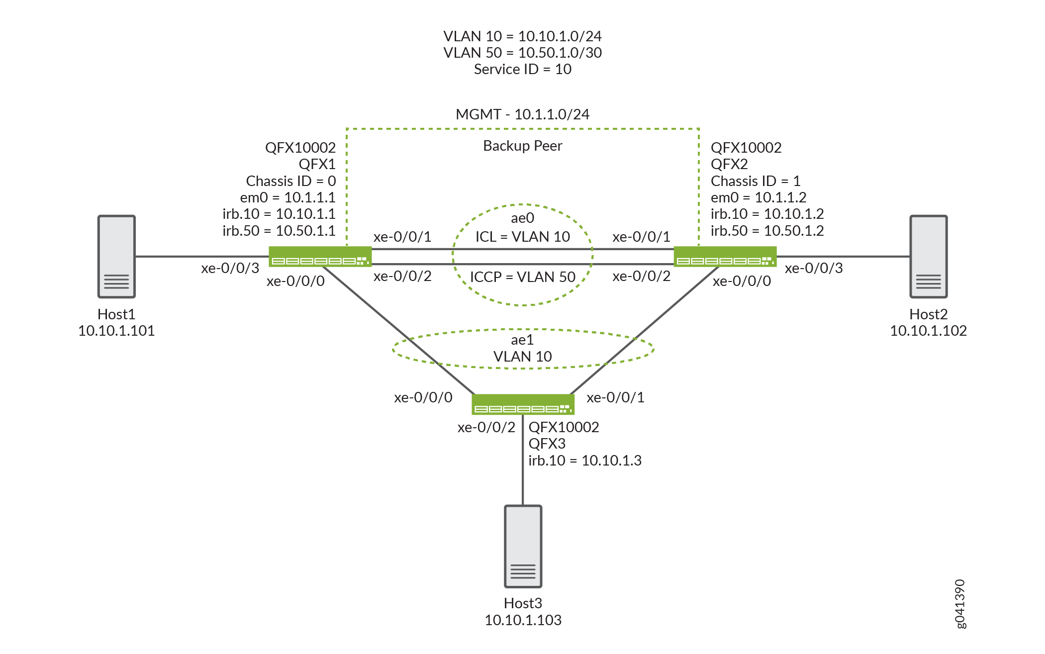
此示例说明了多机箱链路聚合组 (MC-LAG) 如何使客户端设备能够在两台交换机之间形成逻辑 LAG 接口,从而在两台交换机之间提供冗余和负载平衡、多宿主支持和无环路第 2 层网络,而无需运行生成树协议 (STP)。
要求
此示例使用以下硬件和软件组件:
-
Junos OS QFX5100 独立交换机使用 13.2X51-D10 或更高版本,QFX10002独立交换机使用 15.1X53-D10 或更高版本。
-
在 Junos OS 17.3R1 版上对 QFX5100 和 QFX10000 交换机进行了重新验证。
-
在 Junos OS 19.4R1 版上重新验证了 QFX10000 交换机。
-
配置 MC-LAG 之前,请确保您了解如何:
-
在交换机上配置聚合以太网接口。请参阅 示例:在 QFX 系列产品与聚合交换机之间配置链路聚合。
-
在交换机上的聚合以太网接口上配置链路聚合控制协议 (LACP)。请参阅 示例:在 QFX 系列产品与聚合交换机之间使用 LACP 配置链路聚合。
概述
在此示例中,您将跨两台交换机配置 MC-LAG,包括两个聚合以太网接口、一个机箱间控制链路保护链路 (ICL-PL)、用于 ICL-PL 的多机箱保护链路、用于托管 MC-LAG 的对等方的机箱间控制协议以及 MC-LAG 对等方之间的第 3 层连接。ICCP 需要第 3 层连接。
配置
CLI 快速配置
要快速配置此示例,请复制以下命令,将其粘贴到文本文件中,删除所有换行符,更改详细信息,以便与网络配置匹配,将命令复制并粘贴到层次结构级别的 [edit] CLI 中,然后从配置模式进入。commit
QFX1
set chassis aggregated-devices ethernet device-count 2
set interfaces xe-0/0/0 ether-options 802.3ad ae1
set interfaces xe-0/0/1 ether-options 802.3ad ae0
set interfaces xe-0/0/2 ether-options 802.3ad ae0
set interfaces xe-0/0/3 unit 0 family ethernet-switching interface-mode access
set interfaces xe-0/0/3 unit 0 family ethernet-switching vlan members v10
set interfaces ae0 aggregated-ether-options lacp active
set interfaces ae0 unit 0 family ethernet-switching interface-mode trunk
set interfaces ae0 unit 0 family ethernet-switching vlan members v50
set interfaces ae0 unit 0 family ethernet-switching vlan members v10
set interfaces ae1 aggregated-ether-options lacp active
set interfaces ae1 aggregated-ether-options lacp system-id 00:01:02:03:04:05
set interfaces ae1 aggregated-ether-options lacp admin-key 3
set interfaces ae1 aggregated-ether-options mc-ae mc-ae-id 3
set interfaces ae1 aggregated-ether-options mc-ae redundancy-group 1
set interfaces ae1 aggregated-ether-options mc-ae chassis-id 0
set interfaces ae1 aggregated-ether-options mc-ae mode active-active
set interfaces ae1 aggregated-ether-options mc-ae status-control active
set interfaces ae1 aggregated-ether-options mc-ae init-delay-time 240
set interfaces ae1 unit 0 family ethernet-switching interface-mode trunk
set interfaces ae1 unit 0 family ethernet-switching vlan members v10
set interfaces em0 unit 0 family inet address 10.1.1.1/24
set interfaces irb unit 10 family inet address 10.10.1.1/24
set interfaces irb unit 50 family inet address 10.50.1.1/30
set multi-chassis multi-chassis-protection 10.50.1.2 interface ae0
set protocols iccp local-ip-addr 10.50.1.1
set protocols iccp peer 10.50.1.2 session-establishment-hold-time 340
set protocols iccp peer 10.50.1.2 redundancy-group-id-list 1
set protocols iccp peer 10.50.1.2 backup-liveness-detection backup-peer-ip 10.1.1.2
set protocols iccp peer 10.50.1.2 liveness-detection minimum-receive-interval 1000
set protocols iccp peer 10.50.1.2 liveness-detection transmit-interval minimum-interval 1000
set switch-options service-id 10
set vlans v10 vlan-id 10
set vlans v10 l3-interface irb.10
set vlans v50 vlan-id 50
set vlans v50 l3-interface irb.50
QFX2
set chassis aggregated-devices ethernet device-count 2
set interfaces xe-0/0/0 ether-options 802.3ad ae1
set interfaces xe-0/0/1 ether-options 802.3ad ae0
set interfaces xe-0/0/2 ether-options 802.3ad ae0
set interfaces xe-0/0/3 unit 0 family ethernet-switching interface-mode access
set interfaces xe-0/0/3 unit 0 family ethernet-switching vlan members v10
set interfaces ae0 aggregated-ether-options lacp active
set interfaces ae0 unit 0 family ethernet-switching interface-mode trunk
set interfaces ae0 unit 0 family ethernet-switching vlan members v50
set interfaces ae0 unit 0 family ethernet-switching vlan members v10
set interfaces ae1 aggregated-ether-options lacp active
set interfaces ae1 aggregated-ether-options lacp system-id 00:01:02:03:04:05
set interfaces ae1 aggregated-ether-options lacp admin-key 3
set interfaces ae1 aggregated-ether-options mc-ae mc-ae-id 3
set interfaces ae1 aggregated-ether-options mc-ae redundancy-group 1
set interfaces ae1 aggregated-ether-options mc-ae chassis-id 1
set interfaces ae1 aggregated-ether-options mc-ae mode active-active
set interfaces ae1 aggregated-ether-options mc-ae status-control standby
set interfaces ae1 aggregated-ether-options mc-ae init-delay-time 240
set interfaces ae1 unit 0 family ethernet-switching interface-mode trunk
set interfaces ae1 unit 0 family ethernet-switching vlan members v10
set interfaces em0 unit 0 family inet address 10.1.1.2/24
set interfaces irb unit 10 family inet address 10.10.1.2/24
set interfaces irb unit 50 family inet address 10.50.1.2/30
set multi-chassis multi-chassis-protection 10.50.1.1 interface ae0
set protocols iccp local-ip-addr 10.50.1.2
set protocols iccp peer 10.50.1.1 session-establishment-hold-time 340
set protocols iccp peer 10.50.1.1 redundancy-group-id-list 1
set protocols iccp peer 10.50.1.1 backup-liveness-detection backup-peer-ip 10.1.1.1
set protocols iccp peer 10.50.1.1 liveness-detection minimum-receive-interval 1000
set protocols iccp peer 10.50.1.1 liveness-detection transmit-interval minimum-interval 1000
set switch-options service-id 10
set vlans v10 vlan-id 10
set vlans v10 l3-interface irb.10
set vlans v50 vlan-id 50
set vlans v50 l3-interface irb.50
QFX3
set chassis aggregated-devices ethernet device-count 2
set interfaces xe-0/0/0 ether-options 802.3ad ae1
set interfaces xe-0/0/1 ether-options 802.3ad ae1
set interfaces xe-0/0/2 unit 0 family ethernet-switching interface-mode access
set interfaces xe-0/0/2 unit 0 family ethernet-switching vlan members v10
set interfaces ae1 aggregated-ether-options lacp active
set interfaces ae1 unit 0 family ethernet-switching interface-mode trunk
set interfaces ae1 unit 0 family ethernet-switching vlan members v10
set interfaces em0 unit 0 family inet address 10.1.1.3/24
set interfaces irb unit 10 family inet address 10.10.1.3/24
set vlans v10 vlan-id 10
set vlans v10 l3-interface irb.10
在两台交换机上配置 MC-LAG
分步程序
下面的示例要求您在各个配置层级中进行导航。有关导航 CLI 的信息,请参阅在 配置模式下使用 CLI 编辑器。
要在 MC-LAG 对等方之间启用接口和多机箱保护链路:
-
配置 QFX1 和 QFX2 上的 LAG 数量。
[edit chassis]
user@switch# set aggregated-devices ethernet device-count 2
-
将成员接口添加到 QFX1 和 QFX2 上的聚合以太网接口。
QFX1 and QFX2:
[edit interfaces]
user@switch# set xe-0/0/0 ether-options 802.3ad ae1
[edit interfaces]
user@switch# set xe-0/0/1 ether-options 802.3ad ae0
[edit interfaces]
user@switch# set xe-0/0/2 ether-options 802.3ad ae0
-
配置到连接终端主机的接入接口。
[edit interfaces]
user@switch# set xe-0/0/3 unit 0 family ethernet-switching interface-mode access
-
将成员接口添加到 VLAN v10。
[edit interfaces]
user@switch# set interfaces xe-0/0/3 unit 0 family ethernet-switching vlan members v10
-
在 QFX1 和 QFX2 之间配置中继接口。
[edit interfaces]
user@switch# set ae0 unit 0 family ethernet-switching interface-mode trunk
-
在 QFX1 和 QFX2 之间的 MC-LAG 上启用 VLAN。
[edit]
user@switch# set vlans v10 vlan-id 10
>[edit]
user@switch# set vlans v50 vlan-id 50
>[edit interfaces]
user@switch# set ae0 unit 0 family ethernet-switching vlan members v10
>[edit interfaces]
user@switch# set ae0 unit 0 family ethernet-switching vlan members v50
-
配置 IRB 50。
>[edit irb]
user@switch# set irb.50
-
将 VLAN 50 分配给 irb.50。
>[edit]
user@switch# set vlans v50 l3-interface irb.50
-
配置 IRB 10。
>[edit irb]
user@switch# set irb.10
-
分配 VLAN 10 IRB.10。
>[edit]
user@switch# set vlans v10 l3-interface irb.10
-
在 QFX1 和 QFX2 上的 MC-LAG 接口上启用 LACP。
注意:至少一端需要处于活动状态。另一端可以是主动的,也可以是无源的。
>[edit interfaces]
user@switch# set ae0 aggregated-ether-options lacp active

[edit interfaces]
user@switch# set ae1 aggregated-ether-options lacp active
-
为 QFX1 和 QFX2 上的 MC-LAG 指定相同的 LACP 系统 ID。
>[edit interfaces]
user@switch# set ae1 aggregated-ether-options lacp system-ID 00:01:02:03:04:05
-
在 QFX1 和 QFX2 上指定相同的 LACP 管理密钥。
>[edit interfaces]
user@switch# set ae1 aggregated-ether-options lacp admin-key 3
-
在 QFX1 和 QFX2 上的两个 MC-LAG 对等方上指定相同的多机箱聚合以太网识别号。
>[edit interfaces]
user@switch# set ae1 aggregated-ether-options mc-ae mc-ae-id 3
-
为 QFX1 和 QFX2 上的 MC-LAG 对等方上的 MC-LAG 指定唯一的机箱 ID。
>QFX1:
[edit interfaces]
user@switch# set ae1 aggregated-ether-options mc-ae chassis-id 0
>QFX2:
[edit interfaces]
user@switch# set ae1 aggregated-ether-options mc-ae chassis-id 1
-
指定 MC-LAG 在 QFX1 和 QFX2 上的运行模式。
注意:目前仅支持主动-主动模式。
>[edit interfaces]
user@switch# set ae1 aggregated-ether-options mc-ae mode active-active
-
指定 QFX1 和 QFX2 上的 MC-LAG 状态控制。
注意:您必须在托管 MC-LAG 的 QFX1 和 QFX2 上配置状态控制。如果一个对等方处于活动模式,则另一个对等方必须处于备用模式。
>QFX1:
[edit interfaces]
user@switch# set ae1 aggregated-ether-options mc-ae status-control active
>QFX2:
[edit interfaces]
user@switch# set ae1 aggregated-ether-options mc-ae status-control standby
-
指定重新启动 QFX1 和 QFX2 后,多机箱聚合以太网接口的启动应延迟的秒数。
注意:最大 VLAN 配置(例如 4,000 个 VLAN)的建议值为 240 秒。如果在所有 VLAN 上都启用了 IGMP 侦听,则建议值为 420 秒。
>[edit interfaces]
user@switch# set ae1 aggregated-ether-options mc-ae init-delay-time 240
-
在 QFX1 和 QFX2 上的 MC-LAG 对等方之间配置第 3 层连接。
>[edit vlans]
user@switch# set v50 vlan-id 50
>[edit vlans]
user@switch# set v50 l3-interface irb.50
>[edit interfaces]
user@switch# set ae0 unit 0 family ethernet-switching interface-mode trunk vlan members v50
-
在 QFX1 和 QFX2 之间配置多机箱保护链路。
>QFX1:
[edit]
user@switch# set multi-chassis multi-chassis-protection 10.50.1.2 interface ae0
>QFX2:
[edit]
user@switch# set multi-chassis multi-chassis-protection 10.50.1.1 interface ae0
-
将本地 IP 地址配置为 QFX1 和 QFX2 上的 ICCP 连接中。
>QFX1:
[edit protocols]
user@switch# set iccp local-ip-addr 10.50.1.1
>QFX2:
[edit protocols]
user@switch# set iccp local-ip-addr 10.50.1.2
-
(选答)配置 QFX1 和 QFX2 上的 MC-LAG 对等方之间 ICCP 连接必须成功的时间。
注意:在 QFX 系列交换机上,默认会话建立保持时间为 300 秒。但是,会话建立时间必须至少比初始化延迟时间高 100 秒。您可以选择将会话建立时间更新为 340 秒,将初始化延迟时间更新为 240 秒。
>QFX1:
[edit protocols]
user@switch# set iccp peer 10.50.1.2 session-establishment-hold-time 340
>QFX2:
[edit protocols]
user@switch# set iccp peer 10.50.1.1 session-establishment-hold-time 340
-
在 QFX1 和 QFX2 上配置 ICCP 的冗余组。
>QFX1:
[edit protocols]
user@switch# set iccp peer 10.50.1.2 redundancy-group-id-list 1
>QFX2:
[edit protocols]
user@switch# set iccp peer 10.50.1.1 redundancy-group-id-list 1
-
(选答)配置要用于 QFX1 和 QFX2 上的备份活跃度检测的备用 IP 地址。
注意:默认情况下,未启用备份活动性检测。配置备用 IP 地址有助于在 MC-LAG 对等方重新启动期间实现亚秒级流量丢失。
>QFX1:
[edit protocols]
user@switch# set iccp peer 10.50.1.2 backup-liveness-detection backup-peer-ip 10.1.1.2
>QFX2:
[edit protocols]
user@switch# set iccp peer 10.50.1.1 backup-liveness-detection backup-peer-ip 10.1.1.1
-
为 QFX1 和 QFX2 上的 ICCP 配置 BFD 会话的对等 IP 地址和最小接收间隔。
>QFX1:
[edit protocols]
user@switch# set iccp peer 10.50.1.2 liveness-detection minimum-receive-interval 1000
>QFX2:
[edit protocols]
user@switch# set iccp peer 10.50.1.1 liveness-detection minimum-receive-interval 1000
-
为 QFX1 和 QFX2 上的 ICCP 配置 BFD 会话的对等 IP 地址和最小传输间隔。
>QFX1:
[edit protocols]
user@switch# set iccp peer 10.50.1.2 liveness-detection transmit-interval minimum-interval 1000
>QFX2:
[edit protocols]
user@switch# set iccp peer 10.50.1.1 liveness-detection transmit-interval minimum-interval 1000
-
要在 QFX1 和 QFX2 上启用服务 ID:
交换机服务 ID 用于跨 MC-LAG 成员同步应用、IGMP、ARP 和 MAC 学习。
>[edit switch-options]
user@switch# set service-id 10
结果
以下是您在 QFX1 上的配置结果。
chassis {
    aggregated-devices {
        ethernet {
            device-count 2;
        }
    }
}
interfaces {
    xe-0/0/0 {
        ether-options {
            802.3ad ae1;
        }
    }
    xe-0/0/1 {
        ether-options {
            802.3ad ae0;
        }
    }
    xe-0/0/2 {
        ether-options {
            802.3ad ae0;
        }
    }
    xe-0/0/3 {
        unit 0 {
            family ethernet-switching {
                interface-mode access;
                vlan {
                    members v10;
                }
            }
        }
    }
    ae0 {
        aggregated-ether-options {
            lacp {
                active;
            }
        }
        unit 0 {
            family ethernet-switching {
                interface-mode trunk;
                vlan {
                    members [ v50 v10 ];
                }
            }
        }
    }
    ae1 {
        aggregated-ether-options {
            lacp {
                active;
                system-id 00:01:02:03:04:05;
                admin-key 3;
            }
            mc-ae {
                mc-ae-id 3;
                redundancy-group 1;
                chassis-id 0;
                mode active-active;
                status-control active;
                init-delay-time 240;
            }
        }
        unit 0 {
            family ethernet-switching {
                interface-mode trunk;
                vlan {
                    members v10;
                }
            }
        }
    }
    em0 {
        unit 0 {
            family inet {
                address 10.1.1.1/24;
            }
        }
    }
    irb {
        unit 10 {
            family inet {
                address 10.10.1.1/24;
            }
        }
        unit 50 {
            family inet {
                address 10.50.1.1/30;
            }
        }
    }
}
multi-chassis {
    multi-chassis-protection 10.50.1.2 {
        interface ae0;
    }
}
protocols {
    iccp {
        local-ip-addr 10.50.1.1;
        peer 10.50.1.2 {
            session-establishment-hold-time 340;
            redundancy-group-id-list 1;
            backup-liveness-detection {
                backup-peer-ip 10.1.1.2;
            }
            liveness-detection {
                minimum-receive-interval 1000;
                transmit-interval {
                    minimum-interval 1000;
                }
            }
        }
    }
}
switch-options {
    service-id 10;
}
vlans {
    v10 {
        vlan-id 10;
        l3-interface irb.10;
    }
    v50 {
        vlan-id 50;
        l3-interface irb.50;
    }
}
显示 QFX2 上的配置结果。
chassis {
    aggregated-devices {
        ethernet {
            device-count 2;
        }
    }
}
interfaces {
    xe-0/0/0 {
        ether-options {
            802.3ad ae1;
        }
    }
    xe-0/0/1 {
        ether-options {
            802.3ad ae0;
        }
    }
    xe-0/0/2 {
        ether-options {
            802.3ad ae0;
        }
    }
    xe-0/0/3 {
        unit 0 {
            family ethernet-switching {
                interface-mode access;
                vlan {
                    members v10;
                }
            }
        }
    }
    ae0 {
        aggregated-ether-options {
            lacp {
                active;
            }
        }
        unit 0 {
            family ethernet-switching {
                interface-mode trunk;
                vlan {
                    members [ v50 v10 ];
                }
            }
        }
    }
    ae1 {
        aggregated-ether-options {
            lacp {
                active;
                system-id 00:01:02:03:04:05;
                admin-key 3;
            }
            mc-ae {
                mc-ae-id 3;
                redundancy-group 1;
                chassis-id 1;
                mode active-active;
                status-control standby;
                init-delay-time 240;
            }
        }
        unit 0 {
            family ethernet-switching {
                interface-mode trunk;
                vlan {
                    members v10;
                }
            }
        }
    }
    em0 {
        unit 0 {
            family inet {
                address 10.1.1.2/24;
            }
        }
    }
    irb {
        unit 10 {
            family inet {
                address 10.10.1.2/24;
            }
        }
        unit 50 {
            family inet {
                address 10.50.1.2/30;
            }
        }
    }
}
multi-chassis {
    multi-chassis-protection 10.50.1.1 {
        interface ae0;
    }
}
protocols {
    iccp {
        local-ip-addr 10.50.1.2;
        peer 10.50.1.1 {
            session-establishment-hold-time 340;
            redundancy-group-id-list 1;
            backup-liveness-detection {
                backup-peer-ip 10.1.1.1;
            }
            liveness-detection {
                minimum-receive-interval 1000;
                transmit-interval {
                    minimum-interval 1000;
                }
            }
        }
    }
}
switch-options {
    service-id 10;
}
vlans {
    v10 {
        vlan-id 10;
        l3-interface irb.10;
    }
    v50 {
        vlan-id 50;
        l3-interface irb.50;
    }
}
显示 QFX3 上的配置结果。
chassis {
    aggregated-devices {
        ethernet {
            device-count 2;
        }
    }
}
interfaces {
    xe-0/0/0 {
        ether-options {
            802.3ad ae1;
        }
    }
    xe-0/0/1 {
        ether-options {
            802.3ad ae1;
        }
    }
    xe-0/0/2 {
        unit 0 {
            family ethernet-switching {
                interface-mode access;
                vlan {
                    members v10;
                }
            }
        }
    }
    ae1 {
        aggregated-ether-options {
            lacp {
                active;
            }
        }
        unit 0 {
            family ethernet-switching {
                interface-mode trunk;
                vlan {
                    members v10;
                }
            }
        }
    }
    em0 {
        unit 0 {
            family inet {
                address 10.1.1.3/24;
            }
        }
    }
    irb {
        unit 10 {
            family inet {
                address 10.10.1.3/24;
            }
        }
    }
}
vlans {
    v10 {
        vlan-id 10;
        l3-interface irb.10;
    }
}
验证
验证配置是否工作正常。
- 验证 ICCP 是否在 QFX1 上正常工作
- 验证 LACP 是否在 QFX1 上处于活动状态
- 验证 QFX1 上的 MC-AE 和 ICL-PL 接口是否已开启
- 验证 QFX1 上是否正在进行 MAC 学习
- 验证主机 1 是否可以连接到主机 2
验证 ICCP 是否在 QFX1 上正常工作
目的
验证 ICCP 是否在 QFX1 上运行。
行动
user@switch> show iccp
Redundancy Group Information for peer 10.50.1.2
  TCP Connection       : Established
  Liveliness Detection : Up
  Backup liveness peer status: Up
  Redundancy Group ID          Status
    1                           Up

Client Application: lacpd
  Redundancy Group IDs Joined: 1

Client Application: l2ald_iccpd_client
  Redundancy Group IDs Joined: 1
意义
此输出显示,托管 MC-LAG 的对等方之间的 TCP 连接已开启,活度检测已开启,并且 MCSNOOPD 和 ESWD 客户端应用程序正在运行。
验证 LACP 是否在 QFX1 上处于活动状态
目的
验证 LACP 在 QFX1 上是否处于活动状态。
行动
user@switch> show lacp interfaces
Aggregated interface: ae0
    LACP state:       Role   Exp   Def  Dist  Col  Syn  Aggr  Timeout  Activity
      xe-0/0/1       Actor    No    No   Yes  Yes  Yes   Yes     Fast    Active
      xe-0/0/1     Partner    No    No   Yes  Yes  Yes   Yes     Fast    Active
      xe-0/0/2       Actor    No    No   Yes  Yes  Yes   Yes     Fast    Active
      xe-0/0/2     Partner    No    No   Yes  Yes  Yes   Yes     Fast    Active
    LACP protocol:        Receive State  Transmit State          Mux State
      xe-0/0/1                  Current   Fast periodic Collecting distributing
      xe-0/0/2                  Current   Fast periodic Collecting distributing

Aggregated interface: ae1
    LACP state:       Role   Exp   Def  Dist  Col  Syn  Aggr  Timeout  Activity
      xe-0/0/0       Actor    No    No   Yes  Yes  Yes   Yes     Fast    Active
      xe-0/0/0     Partner    No    No   Yes  Yes  Yes   Yes     Fast    Active
    LACP protocol:        Receive State  Transmit State          Mux State
      xe-0/0/0                  Current   Fast periodic Collecting distributing
意义
此输出显示 QFX1 正在参与 LACP 协商。
验证 QFX1 上的 MC-AE 和 ICL-PL 接口是否已开启
目的
验证 QFX1 上的 MC-AE 和 ICL-PL 接口是否已开启。
行动
user@switch> show interfaces mc-ae
 Member Link                  : ae1
 Current State Machine's State: mcae active state
 Local Status                 : active
 Local State                  : up
 Peer Status                  : active
 Peer State                   : up
     Logical Interface        : ae1.0
     Topology Type            : bridge
     Local State              : up
     Peer State               : up
     Peer Ip/MCP/State        : 10.50.1.2 ae0.0 up
意义
此输出显示 QFX1 上的 MC-AE 接口已启动且处于活动状态。
验证 QFX1 上是否正在进行 MAC 学习
目的
验证 MAC 学习是否在 QFX1 上正常工作。
行动
user@switch> show ethernet-switching table
MAC flags (S - static MAC, D - dynamic MAC, L - locally learned, P - Persistent static, C - Control MAC
           SE - statistics enabled, NM - non configured MAC, R - remote PE MAC, O - ovsdb MAC)


Ethernet switching table : 3 entries, 3 learned
Routing instance : default-switch
    Vlan                MAC                 MAC         Age    Logical                NH        RTR
    name                address             flags              interface              Index     ID
    v10                 00:50:56:93:73:cd   DR            -   ae0.0                  0         0
    v10                 00:50:56:93:87:58   DL            -   xe-0/0/3.0             0         0
    v10                 00:50:56:93:89:a0   DLR           -   ae1.0                  0         0
意义
输出显示三个学习的 MAC 地址条目。
验证主机 1 是否可以连接到主机 2
目的
验证 Host1 是否可以对 Host2 执行 ping 操作。
行动
[edit]
user@HOST1> ping 10.10.1.102
PING 10.10.1.102 (10.10.1.102): 56 data bytes
64 bytes from 10.10.1.102: icmp_seq=0 ttl=64 time=157.788 ms
64 bytes from 10.10.1.102: icmp_seq=1 ttl=64 time=153.965 ms
64 bytes from 10.10.1.102: icmp_seq=2 ttl=64 time=102.126 ms
...
意义
输出显示 HOST1 可以成功 ping HOST2。
示例:在 MX 系列上配置多机箱链路聚合
此示例说明如何在主动-主动场景中配置多机箱链路聚合组 (MC-LAG),该组可在 PE 之间对流量进行负载均衡。
要求
此示例使用以下硬件和软件组件:
此示例也适用于 QFX10002 和 QFX10008 交换机。
-
四台瞻博网络 MX 系列路由器(MX240、MX480、MX960)
-
在所有四台路由器上运行 Junos OS 11.2 或更高版本
概述
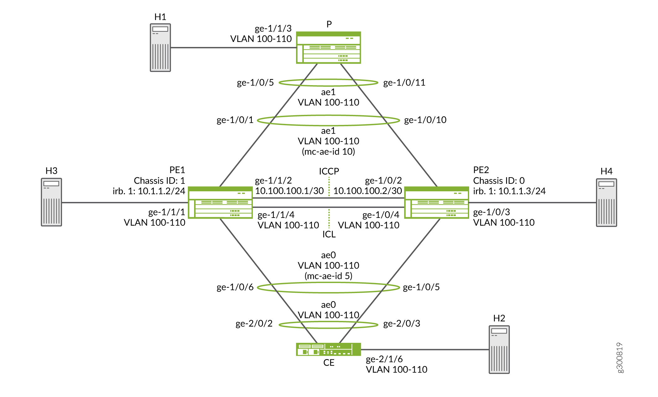
考虑一个示例拓扑,其中客户边缘路由器 客户边缘 分别连接到两个提供商边缘 (PE) 路由器 PE1 和 PE2。两个 PE 设备各有一个连接到客户边缘设备的链路聚合组 (LAG)。配置的模式为 active-active,表示两个 PE 路由器的 LAG 端口处于活动状态并同时传输流量。PE1 和 PE2 连接到单个服务提供商路由器 P。
在此示例中,客户边缘路由器不知道其聚合以太网链路已连接到两个单独的 PE 设备。两个 PE 设备各有一个连接到客户边缘设备的 LAG。配置的模式为主动-主动,这意味着两个 PE 路由器的 LAG 端口处于活动状态并同时传输流量。
在 图 2 中,从路由器客户边缘的角度来看,属于 LAG 的所有四个端口都连接到单个服务提供商设备。由于配置的模式为主动-主动模式,因此所有四个端口都处于活动状态,并且客户边缘设备会均衡到对等 PE 设备的流量负载。在 PE 路由器上,配置了一个面向客户边缘设备的常规 LAG。
MC-LAG 的一端是 MC-LAG 客户端设备,例如在 LAG 中具有一个或多个物理链路的服务器。此客户端设备不需要检测 MC-LAG。MC-LAG 的另一端是两台 MC-LAG 路由器。每个路由器都有一个或多个物理链路连接到单个客户端设备。路由器相互协调,确保正确转发数据流量。
ICCP 消息在两台 PE 设备之间发送。在此示例中,您将跨两台路由器配置 MC-LAG,包括两个聚合以太网接口、一个机箱间链路保护链路 (ICL-PL)、用于 ICL-PL 的多机箱保护链路,以及用于托管 MC-LAG 的对等方的 ICCP。
配置 PE 路由器
CLI 快速配置
要快速配置此示例,请复制以下命令,将其粘贴到文本文件中,删除所有换行符,更改详细信息,以便与网络配置匹配,将命令复制并粘贴到层次结构级别的 [edit] CLI 中,然后从配置模式进入。commit
路由器 PE1
set chassis aggregated-devices ethernet device-count 5
set interfaces ge-1/0/1 gigether-options 802.3ad ae1
set interfaces ge-1/1/2 unit 0 family inet address 10.100.100.1/30
set interfaces ge-1/0/6 gigether-options 802.3ad ae0
set interfaces ge-1/1/1 flexible-vlan-tagging
set interfaces ge-1/1/1 encapsulation flexible-ethernet-services
set interfaces ge-1/1/1 unit 0 encapsulation vlan-bridge
set interfaces ge-1/1/1 unit 0 vlan-id-range 100-110
set interfaces ge-1/1/4 flexible-vlan-tagging
set interfaces ge-1/1/4 encapsulation flexible-ethernet-services
set interfaces ge-1/1/4 unit 0 encapsulation vlan-bridge
set interfaces ge-1/1/4 unit 0 vlan-id-range 100-110
set interfaces ae0 flexible-vlan-tagging
set interfaces ae0 encapsulation flexible-ethernet-services
set interfaces ae0 aggregated-ether-options lacp active
set interfaces ae0 aggregated-ether-options lacp system-priority 100
set interfaces ae0 aggregated-ether-options lacp system-id 00:00:00:00:00:05
set interfaces ae0 aggregated-ether-options lacp admin-key 1
set interfaces ae0 aggregated-ether-options mc-ae mc-ae-id 5
set interfaces ae0 aggregated-ether-options mc-ae redundancy-group 10
set interfaces ae0 aggregated-ether-options mc-ae chassis-id 1
set interfaces ae0 aggregated-ether-options mc-ae mode active-active
set interfaces ae0 aggregated-ether-options mc-ae status-control active
set interfaces ae0 unit 0 encapsulation vlan-bridge
set interfaces ae0 unit 0 vlan-id-range 100-110
set interfaces ae0 unit 0 multi-chassis-protection 10.100.100.2 interface ge-1/1/4.0
set interfaces ae1 flexible-vlan-tagging
set interfaces ae1 encapsulation flexible-ethernet-services
set interfaces ae1 aggregated-ether-options lacp active
set interfaces ae1 aggregated-ether-options lacp system-priority 100
set interfaces ae1 aggregated-ether-options lacp system-id 00:00:00:00:00:05
set interfaces ae1 aggregated-ether-options lacp admin-key 1
set interfaces ae1 aggregated-ether-options mc-ae mc-ae-id 10
set interfaces ae1 aggregated-ether-options mc-ae redundancy-group 10
set interfaces ae1 aggregated-ether-options mc-ae chassis-id 1
set interfaces ae1 aggregated-ether-options mc-ae mode active-active
set interfaces ae1 aggregated-ether-options mc-ae status-control active
set interfaces ae1 unit 0 encapsulation vlan-bridge
set interfaces ae1 unit 0 vlan-id-range 100-110
set interfaces ae1 unit 0 multi-chassis-protection 10.100.100.2 interface ge-1/1/4.0
set bridge-domains bd0 domain-type bridge
set bridge-domains bd0 vlan-id all
set bridge-domains bd0 service-id 20
set bridge-domains bd0 interface ae1.0
set bridge-domains bd0 interface ge-1/0/3.0
set bridge-domains bd0 interface ge-1/1/1.0
set bridge-domains bd0 interface ge-1/1/4.0
set bridge-domains bd0 interface ae0.0
set protocols iccp local-ip-addr 10.100.100.1
set protocols iccp peer 10.100.100.2 redundancy-group-id-list 10
set protocols iccp peer 10.100.100.2 liveness-detection minimum-interval 1000
set switch-options service-id 10
路由器 PE2
set chassis aggregated-devices ethernet device-count 5
set interfaces ge-1/0/2 unit 0 family inet address 10.100.100.2/30
set interfaces ge-1/0/3 flexible-vlan-tagging
set interfaces ge-1/0/3 encapsulation flexible-ethernet-services
set interfaces ge-1/0/3 unit 0 encapsulation vlan-bridge
set interfaces ge-1/0/3 unit 0 vlan-id-range 100-110
set interfaces ge-1/0/4 flexible-vlan-tagging
set interfaces ge-1/0/4 encapsulation flexible-ethernet-services
set interfaces ge-1/0/4 unit 0 encapsulation vlan-bridge
set interfaces ge-1/0/4 unit 0 vlan-id-range 100-110
set interfaces ge-1/0/5 gigether-options 802.3ad ae0
set interfaces ge-1/1/0 gigether-options 802.3ad ae1
set interfaces ae0 flexible-vlan-tagging
set interfaces ae0 encapsulation flexible-ethernet-services
set interfaces ae0 aggregated-ether-options lacp active
set interfaces ae0 aggregated-ether-options lacp system-priority 100
set interfaces ae0 aggregated-ether-options lacp system-id 00:00:00:00:00:05
set interfaces ae0 aggregated-ether-options lacp admin-key 1
set interfaces ae0 aggregated-ether-options mc-ae mc-ae-id 5
set interfaces ae0 aggregated-ether-options mc-ae redundancy-group 10
set interfaces ae0 aggregated-ether-options mc-ae chassis-id 0
set interfaces ae0 aggregated-ether-options mc-ae mode active-active
set interfaces ae0 aggregated-ether-options mc-ae status-control standby
set interfaces ae0 unit 0 encapsulation vlan-bridge
set interfaces ae0 unit 0 vlan-id-range 100-110
set interfaces ae0 unit 0 multi-chassis-protection 10.100.100.1 interface ge-1/0/4.0
set interfaces ae1 flexible-vlan-tagging
set interfaces ae1 encapsulation flexible-ethernet-services
set interfaces ae1 aggregated-ether-options lacp active
set interfaces ae1 aggregated-ether-options lacp system-priority 100
set interfaces ae1 aggregated-ether-options lacp system-id 00:00:00:00:00:05
set interfaces ae1 aggregated-ether-options lacp admin-key 1
set interfaces ae1 aggregated-ether-options mc-ae mc-ae-id 10
set interfaces ae1 aggregated-ether-options mc-ae redundancy-group 10
set interfaces ae1 aggregated-ether-options mc-ae chassis-id 0
set interfaces ae1 aggregated-ether-options mc-ae mode active-active
set interfaces ae1 aggregated-ether-options mc-ae status-control standby
set interfaces ae1 unit 0 encapsulation vlan-bridge
set interfaces ae1 unit 0 vlan-id-range 100-110
set interfaces ae1 unit 0 multi-chassis-protection 10.100.100.1 interface ge-1/0/4.0
set bridge-domains bd0 domain-type bridge
set bridge-domains bd0 vlan-id all
set bridge-domains bd0 service-id 20
set bridge-domains bd0 interface ae1.0
set bridge-domains bd0 interface ge-1/0/3.0
set bridge-domains bd0 interface ge-1/0/4.0
set bridge-domains bd0 interface ae0.0
set protocols iccp local-ip-addr 10.100.100.2
set protocols iccp peer 10.100.100.1 redundancy-group-id-list 10
set protocols iccp peer 10.100.100.1 liveness-detection minimum-interval 1000
set switch-options service-id 10
配置 PE1 路由器
分步程序
下面的示例要求您在各个配置层级中进行导航。有关导航 CLI 的信息,请参阅 在 配置模式下使用 CLI 编辑器 。
要配置路由器 PE1,请执行以下操作:
-
指定要创建的聚合以太网接口数量。
[edit chassis]
user@PE1# set aggregated-devices ethernet device-count 5
-
指定要包含在聚合以太网捆绑包中的成员。
[edit interfaces]
user@PE1# set ge-1/0/1 gigether-options 802.3ad ae1
user@PE1# set ge-1/0/6 gigether-options 802.3ad ae0
-
配置连接到发送方或接收方的接口、ICL 接口和 ICCP 接口。
[edit interfaces]
user@PE1# set ge-1/1/1 flexible-vlan-tagging
user@PE1# set ge-1/1/1 encapsulation flexible-ethernet-services
user@PE1# set ge-1/1/1 unit 0 encapsulation vlan-bridge
user@PE1# set ge-1/1/1 unit 0 vlan-id-range 100-110

user@PE1# set ge-1/1/4 flexible-vlan-tagging
user@PE1# set ge-1/1/4 encapsulation flexible-ethernet-services
user@PE1# set ge-1/1/4 unit 0 encapsulation vlan-bridge
user@PE1# set ge-1/1/4 unit 0 vlan-id-range 100-110

user@PE1# set ge-1/1/2 unit 0 family inet address 10.100.100.1/30
-
在聚合以太网捆绑包上配置参数。
[edit interfaces ae0]
user@PE1# set flexible-vlan-tagging
user@PE1# set encapsulation flexible-ethernet-services
user@PE1# set unit 0 encapsulation vlan-bridge
user@PE1# set unit 0 vlan-id-range 100-110
user@PE1# set unit 0 multi-chassis-protection 10.100.100.2 interface ge-1/1/4.0
[edit interfaces ae1]
user@PE1# set flexible-vlan-tagging
user@PE1# set encapsulation flexible-ethernet-services
user@PE1# set unit 0 encapsulation vlan-bridge
user@PE1# set unit 0 vlan-id-range 100-110
user@PE1# set unit 0 multi-chassis-protection 10.100.100.2 interface ge-1/1/4.0
-
在聚合以太网捆绑包上配置 LACP。
[edit interfaces ae0 aggregated-ether-options]
user@PE1# set lacp active
user@PE1# set lacp system-priority 100
user@PE1# set lacp system-id 00:00:00:00:00:05
user@PE1# set lacp admin-key 1
[edit interfaces ae1 aggregated-ether-options]
user@PE1# set lacp active
user@PE1# set lacp system-priority 100
user@PE1# set lacp system-id 00:00:00:00:00:05
user@PE1# set lacp admin-key 1
-
配置 MC-LAG 接口。
[edit interfaces ae0 aggregated-ether-options]
user@PE1# set mc-ae mc-ae-id 5
user@PE1# set mc-ae redundancy-group 10
user@PE1# set mc-ae chassis-id 1
user@PE1# set mc-ae mode active-active
user@PE1# set mc-ae status-control active
[edit interfaces ae1 aggregated-ether-options]
user@PE1# set mc-ae mc-ae-id 10
user@PE1# set mc-ae redundancy-group 10
user@PE1# set mc-ae chassis-id 1
user@PE1# set mc-ae mode active-active
user@PE1# set mc-ae status-control active
多机箱聚合以太网识别号 (mc-ae-id) 指定聚合以太网接口属于哪个链路聚合组。路由器 PE1 和路由器 PE2 上的 ae0 接口配置了 mc-ae-id 5。路由器 PE1 和路由器 PE2 上的 ae1 接口配置了 mc-ae-id 10。
redundancy-group 10ICCP 使用此语句将执行类似冗余功能的多个机箱关联起来,并建立通信通道,以便对等机箱上的应用可以相互发送消息。路由器 PE1 和路由器 PE2 上的 ae0 和 ae1 接口配置了相同的冗余组,即冗余组 10。LACP 使用该
chassis-id语句来计算 MC-LAG 物理成员链路的端口号。路由器 PE1 使用 chassid-id 1 来识别其 ae0 和 ae1 接口。路由器 PE2 使用 机箱 ID 0 来识别其 ae0 和 ae1 接口。该语句指示
modeMC-LAG 是处于主动-备用模式还是主动-主动模式。同一组中的机箱必须处于同一模式。 -
配置包含逻辑端口集的域。
[edit bridge-domains bd0]
user@PE1# set domain-type bridge
user@PE1# set vlan-id all
user@PE1# set service-id 20
user@PE1# set interface ae0.0
user@PE1# set interface ae1.0
user@PE1# set interface ge-1/1/1.0
user@PE1# set interface ge-1/1/4.0
网桥域中的端口具有相同的泛洪或广播特征,以便执行第 2 层桥接。
要跨对等方(在本例中为路由器 PE1 和路由器 PE2)之间链接相关的网桥域,需要使用桥接级别
service-id语句,并且必须配置相同的值。 -
配置 ICCP 参数。
[edit protocols iccp]
user@PE1# set local-ip-addr 10.100.100.1
user@PE1# set peer 10.100.100.2 redundancy-group-id-list 10
user@PE1# set peer 10.100.100.2 liveness-detection minimum-interval 1000
-
在全局级别配置服务 ID。
[edit switch-options]
user@PE1# set service-id 10
您必须为提供服务的 PE 路由器集中的服务配置相同的唯一网络范围配置。如果多机箱聚合以太网接口是桥接域的一部分,则需要使用此服务 ID。
结果
在配置模式下,输入 show bridge-domains、 show chassis、 show protocolsshow interfaces和show switch-options命令以确认您的配置。如果输出未显示预期的配置,请重复此示例中的说明以更正配置。
user@PE1#  show bridge-domains
bd0 {
    domain-type bridge;
    vlan-id all;
    service-id 20;
    interface ae1.0;
    interface ge-1/1/1.0;
    interface ge-1/1/4.0;
    interface ae0.0;
}
user@PE1#  show chassis
aggregated-devices {
    ethernet {
        device-count 5;
    }
}
user@PE1#  show interfaces
ge-1/0/1 {
    gigether-options {
        802.3ad ae1;
    }
}
ge-1/0/6 {
    gigether-options {
        802.3ad ae0;
    }
}
ge-1/1/2 {
    unit 0 {
        family inet {
            address 10.100.100.1/30;
        }
    }
}
ge-1/1/1 {
    flexible-vlan-tagging;
    encapsulation flexible-ethernet-services;
    unit 0 {
        encapsulation vlan-bridge;
        vlan-id-range 100-110;
    }
}
ge-1/1/4 {
    flexible-vlan-tagging;
    encapsulation flexible-ethernet-services;
    unit 0 {
        encapsulation vlan-bridge;
        vlan-id-range 100-110;
    }
}
ae0 {
    flexible-vlan-tagging;
    encapsulation flexible-ethernet-services;
    aggregated-ether-options {
        lacp {
            active;
            system-priority 100;
            system-id 00:00:00:00:00:05;
            admin-key 1;
        }
        mc-ae {
            mc-ae-id 5;
            redundancy-group 10;
            chassis-id 1;
            mode active-active;
            status-control active;
        }
    }
    unit 0 {
        encapsulation vlan-bridge;
        vlan-id-range 100-110;
        multi-chassis-protection 10.100.100.2 {
            interface ge-1/1/4.0;
        }
    }
}
ae1 {
    flexible-vlan-tagging;
    encapsulation flexible-ethernet-services;
    aggregated-ether-options {
        lacp {
            active;
            system-priority 100;
            system-id 00:00:00:00:00:05;
            admin-key 1;
        }
        mc-ae {
            mc-ae-id 10;
            redundancy-group 10;
            chassis-id 1;
            mode active-active;
            status-control active;
        }
    }
    unit 0 {
        encapsulation vlan-bridge;
        vlan-id-range 100-110;
        multi-chassis-protection 10.100.100.2 {
            interface ge-1/1/4.0;
        }
    }
}
user@PE1#  show protocols
iccp {
    local-ip-addr 10.100.100.1;
    peer 10.100.100.2 {
        redundancy-group-id-list 10;
        liveness-detection {
            minimum-interval 1000;
        }
    }
}
user@PE1#  show switch-options
service-id 10;
如果完成设备配置,请从配置模式输入 commit 。
使用相应的接口名称和地址对路由器 PE2 重复此过程。
配置客户边缘设备
CLI 快速配置
要快速配置此示例,请复制以下命令,将其粘贴到文本文件中,删除所有换行符,更改详细信息以匹配网络配置,将命令复制并粘贴到层次结构级别的 [edit] CLI 中,然后从配置模式进入。commit
设备客户边缘
set chassis aggregated-devices ethernet device-count 2
set interfaces ge-2/0/2 gigether-options 802.3ad ae0
set interfaces ge-2/0/3 gigether-options 802.3ad ae0
set interfaces ge-2/1/6 flexible-vlan-tagging
set interfaces ge-2/1/6 encapsulation flexible-ethernet-services
set interfaces ge-2/1/6 unit 0 encapsulation vlan-bridge
set interfaces ge-2/1/6 unit 0 vlan-id-range 100-110
set interfaces ae0 flexible-vlan-tagging
set interfaces ae0 encapsulation flexible-ethernet-services
set interfaces ae0 aggregated-ether-options lacp active
set interfaces ae0 aggregated-ether-options lacp system-priority 100
set interfaces ae0 unit 0 encapsulation vlan-bridge
set interfaces ae0 unit 0 vlan-id-range 100-110
set bridge-domains bd0 domain-type bridge
set bridge-domains bd0 vlan-id all
set bridge-domains bd0 interface ge-2/1/6.0
set bridge-domains bd0 interface ae0.0
配置客户边缘设备
分步程序
下面的示例要求您在各个配置层级中进行导航。有关导航 CLI 的信息,请参阅 在 配置模式下使用 CLI 编辑器 。
要配置客户边缘设备:
-
指定要创建的聚合以太网接口数量。
[edit chassis]
user@CE# set aggregated-devices ethernet device-count 2
-
指定要包含在聚合以太网捆绑包中的成员。
[edit interfaces]
user@CE# set ge-2/0/2 gigether-options 802.3ad ae0
user@CE# set ge-2/0/3 gigether-options 802.3ad ae0
-
配置连接到发送方或接收方的接口。
[edit interfaces ge-2/1/6]
user@CE# set flexible-vlan-tagging
user@CE# set encapsulation flexible-ethernet-services
user@CE# set unit 0 encapsulation vlan-bridge
user@CE# set unit 0 vlan-id-range 100-110
-
在聚合以太网捆绑包上配置参数。
[edit interfaces ae0]
user@CE# set flexible-vlan-tagging
user@CE# set encapsulation flexible-ethernet-services
user@CE# set unit 0 encapsulation vlan-bridge
user@CE# set unit 0 vlan-id-range 100-110
-
在聚合以太网捆绑包上配置 LACP。
[edit interfaces ae0 aggregated-ether-options]
user@CE# set lacp active
user@CE# set lacp system-priority 100
该
active语句启动 LACP 数据包的传输。对于
system-priority语句,值越小表示优先级越高。系统优先级值较低的设备决定了每个 LACP 组的 LACP 伙伴设备之间的哪些链路处于活动状态,哪些链路处于备用模式。链路控制端上的设备使用端口优先级来确定哪些端口要捆绑到聚合捆绑包中,哪些端口处于备用模式。其他设备(链路的非控制端)上的端口优先级将被忽略。 -
配置包含逻辑端口集的域。
[edit bridge-domains bd0]
user@CE# set domain-type bridge
user@CE# set vlan-id all
user@CE# set interface ge-2/1/6.0
user@CE# set interface ae0.0
网桥域中的端口具有相同的泛洪或广播特征,以便执行第 2 层桥接。
结果
在配置模式下,输入 show bridge-domains、 show chassis和 show interfaces 命令以确认您的配置。如果输出未显示预期的配置,请重复此示例中的说明以更正配置。
user@CE# show bridge-domains
bd0 {
    domain-type bridge;
    vlan-id all;
    interface ge-2/1/6.0;
    interface ae0.0;
}
user@CE# show chassis
aggregated-devices {
    ethernet {
        device-count 2;
    }
}
user@CE# show interfaces
ge-2/0/2 {
    gigether-options {
        802.3ad ae0;
    }
}
ge-2/0/3 {
    gigether-options {
        802.3ad ae0;
    }
}
ge-2/1/6 {
    flexible-vlan-tagging;
    encapsulation flexible-ethernet-services;
    unit 0 {
        encapsulation vlan-bridge;
        vlan-id-range 100-110;
    }
}
ae0 {
    flexible-vlan-tagging;
    encapsulation flexible-ethernet-services;
    aggregated-ether-options {
        lacp {
            active;
            system-priority 100;
        }
    }
    unit 0 {
        encapsulation vlan-bridge;
        vlan-id-range 100-110;
    }
}
如果完成设备配置,请从配置模式输入 commit 。
配置提供商路由器
CLI 快速配置
要快速配置此示例,请复制以下命令,将其粘贴到文本文件中,删除所有换行符,更改详细信息,以便与网络配置匹配,将命令复制并粘贴到层次结构级别的 [edit] CLI 中,然后从配置模式进入。commit
路由器 P
set chassis aggregated-devices ethernet device-count 2
set interfaces ge-1/0/5 gigether-options 802.3ad ae1
set interfaces ge-1/0/11 gigether-options 802.3ad ae1
set interfaces ge-1/1/3 flexible-vlan-tagging
set interfaces ge-1/1/3 encapsulation flexible-ethernet-services
set interfaces ge-1/1/3 unit 0 encapsulation vlan-bridge
set interfaces ge-1/1/3 unit 0 vlan-id-range 100-110
set interfaces ae1 flexible-vlan-tagging
set interfaces ae1 encapsulation flexible-ethernet-services
set interfaces ae1 aggregated-ether-options lacp active
set interfaces ae1 aggregated-ether-options lacp system-priority 100
set interfaces ae1 unit 0 encapsulation vlan-bridge
set interfaces ae1 unit 0 vlan-id-range 100-110
set bridge-domains bd0 vlan-id all
set bridge-domains bd0 domain-type bridge
set bridge-domains bd0 interface ge-1/1/3.0
set bridge-domains bd0 interface ae1.0
配置 PE 路由器
分步程序
下面的示例要求您在各个配置层级中进行导航。有关导航 CLI 的信息,请参阅 在 配置模式下使用 CLI 编辑器 。
要配置 P 路由器,请执行以下操作:
-
指定要创建的聚合以太网接口数量。
[edit chassis]
user@P# set aggregated-devices ethernet device-count 2
-
指定要包含在聚合以太网捆绑包中的成员。
[edit interfaces]
user@P# set ge-1/0/5 gigether-options 802.3ad ae1
user@P# set ge-1/0/11 gigether-options 802.3ad ae1
-
配置连接到发送方或接收方的接口。
[edit interfaces ge-1/1/3]
user@P# set flexible-vlan-tagging
user@P# set encapsulation flexible-ethernet-services
user@P# set unit 0 encapsulation vlan-bridge
user@P# set unit 0 vlan-id-range 100-500
-
在聚合以太网捆绑包上配置参数。
[edit interfaces ae1]
user@P# set flexible-vlan-tagging
user@P# set encapsulation flexible-ethernet-services
user@P# set unit 0 encapsulation vlan-bridge
user@P# set unit 0 vlan-id-range 100-110
-
在聚合以太网捆绑包上配置 LACP。
[edit interfaces ae1 aggregated-ether-options]
user@P# set lacp active
user@P# set lacp system-priority 100
-
配置包含逻辑端口集的域。
[edit bridge-domains bd0]
user@P# set vlan-id all
user@P# set domain-type bridge
user@P# set interface ge-1/1/3.0
user@P# set interface ae1.0
结果
在配置模式下,输入 show bridge-domains、 show chassis和 show interfaces 命令以确认您的配置。如果输出未显示预期的配置,请重复此示例中的说明以更正配置。
user@P#  show bridge-domains
bd0 {
    domain-type bridge;
    vlan-id all;
    interface ge-1/1/3.0;
    interface ae1.0;
}
user@P#  show chassis
aggregated-devices {
    ethernet {
        device-count 2;
    }
}
user@P#  show interfaces
ge-1/0/5 {
    gigether-options {
        802.3ad ae1;
    }
}
ge-1/0/11 {
    gigether-options {
        802.3ad ae1;
    }
}
ge-1/1/3 {
    flexible-vlan-tagging;
    encapsulation flexible-ethernet-services;
    unit 0 {
        encapsulation vlan-bridge;
        vlan-id-range 100-500;
    }
}
ae1 {
    flexible-vlan-tagging;
    encapsulation flexible-ethernet-services;
    aggregated-ether-options {
        lacp {
            active;
            system-priority 100;
        }
    }
    unit 0 {
        encapsulation vlan-bridge;
        vlan-id-range 100-110;
    }
}
如果完成设备配置,请从配置模式输入 commit 。
验证
运行以下命令,确认配置工作正常:
-
show iccp -
show interfaces ae0 -
show interfaces ae1 -
show interfaces mc-ae -
show pim interfaces -
show vrrp -
show igmp -
show ospf -
show dhcp relay
示例:在 QFX 系列交换机和 MX 系列路由器之间配置多机箱链路聚合
此示例说明如何使用主动-主动模式在 QFX 系列交换机和 MX 系列路由器之间配置多机箱链路聚合组 (MC-LAG),以支持第 2 层桥接。在主动-主动模式下,所有成员链路都会传输流量,从而可以将流量负载均衡到两个 MC-LAG 对等方。
要求
此示例使用以下硬件和软件组件:
一台瞻博网络 MX 系列路由器(MX240、MX480、MX960)
一台瞻博网络 QFX 系列交换机(QFX10000、QFX5110、QFX5120)
两台支持 LAG 的服务器;在此示例中,MX 系列路由器扮演了服务器角色
MC-LAG 对等方上的 Junos OS 19.4R1 或更高版本
概述
在示例拓扑中,两台服务器连接到两台提供商边缘 (PE) 设备 S0 和 R1。S0 是 QFX 系列交换机,而 R1 是 MX 系列路由器。两台 PE 设备都有连接到两台服务器的链路聚合组 (LAG)。此示例为 MC-LAG 配置主动-主动模式,表示两个 PE 设备的 LAG 端口处于活动状态并同时传输流量。
服务器不知道其聚合以太网链路已连接到多个 PE 设备。MC-LAG 操作对服务器不透明,并且都配置了传统的以太网 LAG 接口。
MC-LAG 的一端是 MC-LAG 客户端设备,例如服务器或交换/路由设备,其 LAG 中有一个或多个物理链路。客户端设备不需要支持 MC-LAG,因为这些设备只需要支持标准 LAG 接口。MC-LAG 的另一侧是两个 MC-LAG 设备 (PE)。每个 PE 都有一个或多个物理链路连接到客户端设备。PE 设备相互协调,以确保数据流量得到正确转发,即使所有客户端链路都在主动转发流量。
在 图 3 中,服务器的运行方式就好像两个 LAG 成员都连接到单个提供商设备一样。由于配置的模式为主动-主动,因此所有 LAG 成员都处于转发状态,并且客户边缘设备会均衡到对等 PE 设备的流量负载。
机箱间控制协议 (ICCP) 在 PE 设备之间发送消息,以控制 MC-LAG 的转发状态。此外,在主动-主动模式下运行时,机箱间链路保护链路 (ICL-PL) 可用于根据需要在 PE 设备之间转发流量。
在此示例中,您在 PE 上配置两个 MC-LAG,以支持服务器上聚合以太网接口之间的第 2 层连接。作为 MC-LAG 配置的一部分,您可以在 MC-LAG 对等方之间配置聚合以太网接口,以支持 ICL-PL 和 ICCP 功能。
拓扑图
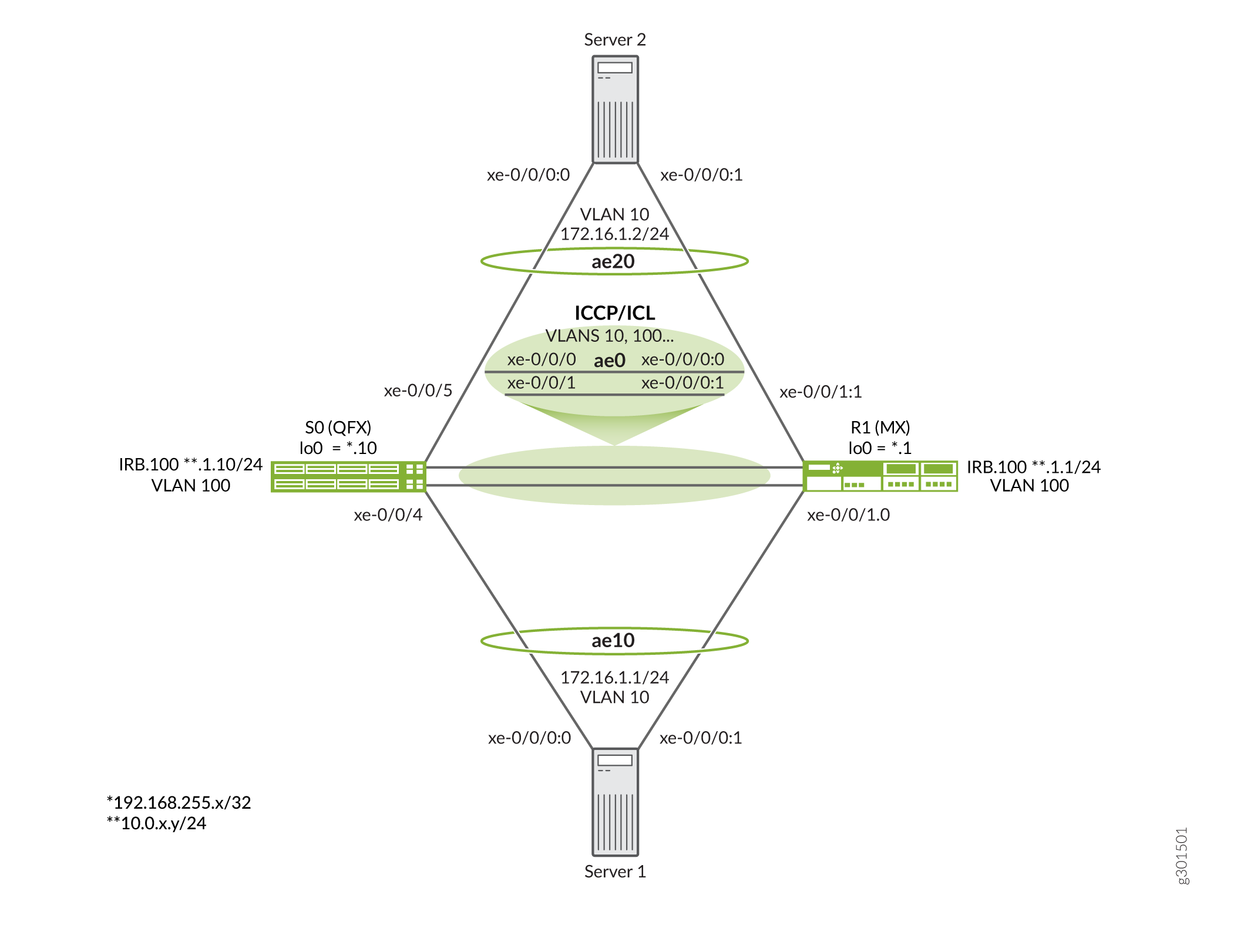
图 3 显示了此示例中使用的拓扑。
关于拓扑结构的要点包括:
- S0 节点是 QFX10000 交换机,而 R1 节点是 MX960 路由器。
- MX 系列路由器用于填补 2 台服务器的角色。此示例中可以使用任何支持基于传统 LACP 的 LAG 接口的交换机、路由器或服务器设备。
- 为服务器分配了 VLAN 10,并具有一个共享子网。您期望服务器之间有第 2 层连接。
- PE 之间的 ICCP 会话锚定到 IRB 接口。这类似于环路接口之间的 BGP 对等互连,以便在链路故障后继续存在。但是,在这里,IRB 被放置在共享 VLAN (VLAN 100) 中,用于在 PE 之间提供第 2 层连接。这意味着 IRB 之间的连接不需要 IGP 或静态路由。因此,IRB 共享一个 IP 子网。
- 此示例在 PE (ae0) 之间部署一个 LAG 接口,以支持 ICCP 和 ICL 功能。如果需要,您可以在单独的 AE 捆绑包上运行 ICCP。强烈建议在用于 ICCP/ICL 链路的 AE 束中使用多个成员,以确保它们在发生单个接口或链路故障时保持运行。
- 虽然基本相似,但 PE 设备之间的 MC-LAG 配置略有不同,因为它们是不同的平台。演示这些配置差异以及平台之间的 MC-LAG 互操作性是创建此示例的原因。在继续执行示例时,请务必跟踪您正在与哪个 PE 交互。
配置设备
CLI 快速配置
要快速配置此示例,请复制以下命令,将其粘贴到文本文件中,删除所有换行符,更改详细信息,以便与网络配置匹配,将命令复制并粘贴到层次结构级别的 [edit] CLI 中。完成后,从配置模式进入 commit 以激活更改。
交换机 S0
在此示例中,S0 设备是 QFX10000 交换机。
set system host-name mc-lag_r0
set chassis aggregated-devices ethernet device-count 10
set interfaces xe-0/0/0 gigether-options 802.3ad ae0
set interfaces xe-0/0/1 gigether-options 802.3ad ae0
set interfaces xe-0/0/4 gigether-options 802.3ad ae10
set interfaces xe-0/0/5 gigether-options 802.3ad ae20
set interfaces ae0 aggregated-ether-options lacp active
set interfaces ae0 unit 0 family ethernet-switching interface-mode trunk
set interfaces ae0 unit 0 family ethernet-switching vlan members all
set interfaces ae10 aggregated-ether-options lacp active
set interfaces ae10 aggregated-ether-options lacp system-id 01:01:01:01:01:01
set interfaces ae10 aggregated-ether-options lacp admin-key 10
set interfaces ae10 aggregated-ether-options mc-ae mc-ae-id 10
set interfaces ae10 aggregated-ether-options mc-ae redundancy-group 1
set interfaces ae10 aggregated-ether-options mc-ae chassis-id 0
set interfaces ae10 aggregated-ether-options mc-ae mode active-active
set interfaces ae10 aggregated-ether-options mc-ae status-control active
set interfaces ae10 unit 0 family ethernet-switching vlan members vlan10
set interfaces ae20 aggregated-ether-options lacp active
set interfaces ae20 aggregated-ether-options lacp system-id 02:02:02:02:02:02
set interfaces ae20 aggregated-ether-options lacp admin-key 20
set interfaces ae20 aggregated-ether-options mc-ae mc-ae-id 20
set interfaces ae20 aggregated-ether-options mc-ae redundancy-group 1
set interfaces ae20 aggregated-ether-options mc-ae chassis-id 1
set interfaces ae20 aggregated-ether-options mc-ae mode active-active
set interfaces ae20 aggregated-ether-options mc-ae status-control standby
set interfaces ae20 unit 0 family ethernet-switching vlan members vlan10
set interfaces irb unit 100 family inet address 10.0.1.10/24
set interfaces lo0 unit 0 family inet address 192.168.255.10/32
set multi-chassis multi-chassis-protection 10.0.1.1 interface ae0
set protocols iccp local-ip-addr 10.0.1.10
set protocols iccp peer 10.0.1.1 session-establishment-hold-time 50
set protocols iccp peer 10.0.1.1 redundancy-group-id-list 1
set protocols iccp peer 10.0.1.1 liveness-detection minimum-interval 1000
set switch-options service-id 100
set vlans vlan10 vlan-id 10
set vlans vlan100 vlan-id 100
set vlans vlan100 l3-interface irb.100
路由器 R1
在此示例中,R1 设备是 MX 系列路由器。
set system host-name mc-lag_r1
set chassis aggregated-devices ethernet device-count 10
set interfaces xe-0/0/0:0 gigether-options 802.3ad ae0
set interfaces xe-0/0/0:1 gigether-options 802.3ad ae0
set interfaces xe-0/0/1:0 gigether-options 802.3ad ae10
set interfaces xe-0/0/1:1 gigether-options 802.3ad ae20
set interfaces ae0 aggregated-ether-options lacp active
set interfaces ae0 unit 0 family bridge interface-mode trunk
set interfaces ae0 unit 0 family bridge vlan-id-list 1-1000
set interfaces ae10 aggregated-ether-options lacp active
set interfaces ae10 aggregated-ether-options lacp system-id 01:01:01:01:01:01
set interfaces ae10 aggregated-ether-options lacp admin-key 10
set interfaces ae10 aggregated-ether-options mc-ae mc-ae-id 10
set interfaces ae10 aggregated-ether-options mc-ae redundancy-group 1
set interfaces ae10 aggregated-ether-options mc-ae chassis-id 1
set interfaces ae10 aggregated-ether-options mc-ae mode active-active
set interfaces ae10 aggregated-ether-options mc-ae status-control standby
set interfaces ae10 unit 0 multi-chassis-protection 10.0.1.10 interface ae0.0
set interfaces ae10 unit 0 family bridge interface-mode access
set interfaces ae10 unit 0 family bridge vlan-id 10
set interfaces ae20 aggregated-ether-options lacp active
set interfaces ae20 aggregated-ether-options lacp system-id 02:02:02:02:02:02
set interfaces ae20 aggregated-ether-options lacp admin-key 20
set interfaces ae20 aggregated-ether-options mc-ae mc-ae-id 20
set interfaces ae20 aggregated-ether-options mc-ae redundancy-group 1
set interfaces ae20 aggregated-ether-options mc-ae chassis-id 0
set interfaces ae20 aggregated-ether-options mc-ae mode active-active
set interfaces ae20 aggregated-ether-options mc-ae status-control active
set interfaces ae20 unit 0 multi-chassis-protection 10.0.1.10 interface ae0.0
set interfaces ae20 unit 0 family bridge interface-mode access
set interfaces ae20 unit 0 family bridge vlan-id 10
set interfaces irb unit 100 family inet address 10.0.1.1/24
set interfaces lo0 unit 0 family inet address 192.168.255.1/32
set protocols iccp local-ip-addr 10.0.1.1
set protocols iccp peer 10.0.1.10 session-establishment-hold-time 50
set protocols iccp peer 10.0.1.10 redundancy-group-id-list 1
set protocols iccp peer 10.0.1.10 liveness-detection minimum-interval 1000
set bridge-domains vlan10 vlan-id 10
set bridge-domains vlan100 vlan-id 100
set bridge-domains vlan100 routing-interface irb.100
set switch-options service-id 10
服务器 1
此示例中的服务器是 MX 路由器。虽然此示例重点介绍如何在 PE 设备上配置 MC-LAG,但为了完整起见,提供了服务器配置。在此示例中,服务器 2 具有相同的配置,只是分配了 IPv4 地址 172.16.1.2/24 和 IPv6 地址 2001:db8:172:16:1::2 。
set system host-name server1
set chassis aggregated-devices ethernet device-count 10
set interfaces xe-0/0/0:0 gigether-options 802.3ad ae10
set interfaces xe-0/0/0:1 gigether-options 802.3ad ae10
set interfaces ae10 aggregated-ether-options lacp active
set interfaces ae10 unit 0 family inet address 172.16.1.1/24
set interfaces ae10 unit 0 family inet6 address 2001:db8:172:16:1::1/64
配置 S0 交换机
分步程序
下面的示例要求您在各个配置层级中进行导航。有关导航 CLI 的信息,请参阅在 配置模式下使用 CLI 编辑器。
要配置交换机 S0,请执行以下操作:
指定机箱上支持的聚合以太网设备数量。示例只需要 3 个 LAG,但具有未使用的 AE 束容量不会导致任何问题。
[edit chassis]
user@S0# set aggregated-devices ethernet device-count 10
配置环路(如果需要,在本例中不使用)和 IRB 接口,以及 IRB 接口的 VLAN。在此示例中,IRB 接口用于锚定 ICCP 会话,并分配给 VLAN 100。
[edit]
user@S0# set interfaces lo0 unit 0 family inet address 192.168.255.10/32
user@S0# set interfaces irb unit 100 family inet address 10.0.1.10/24
user@S0# set vlans vlan100 vlan-id 100
user@S0# set vlans vlan100 l3-interface irb.100
将 ae0 接口配置为支持 ICCP 和 ICL。请务必包括所有 MC-LAG VLAN,以及用于支持 ICCP 的 IRB VLAN。您可以指定 VLAN 列表,但在此示例
all中,关键字用于快速确保 ae0 接口支持所有 VLAN。在此示例中,ISL 上只需要两个 VLAN。支持 ICCP 的 MC-LAG VLAN (10) 和 VLAN 100。要正常运行,单元 0 必须用于 QFX 系列交换机上的 ICL 链路,因为与 MX 系列路由器不同,它们不支持单元级 ICL 链路规范。
注意:QFX 系列交换机仅支持 ICL 链路的接口级别规范,并假定使用单元 0。因此,如图所示,在单元 0 下列出所有 MC-LAG VLAN 非常重要。MX 系列路由器可以支持 ICL 的全局级或单元级规范。本例稍后将显示后一种方法。
[edit interfaces]
user@S0# set xe-0/0/0 gigether-options 802.3ad ae0
user@S0# set xe-0/0/1 gigether-options 802.3ad ae0
user@S0# set ae0 aggregated-ether-options lacp active
user@S0# set ae0 unit 0 family ethernet-switching interface-mode trunk
user@S0# set ae0 unit 0 family ethernet-switching vlan members all
指定用于面向聚合以太网捆绑包的服务器的成员接口。
[edit interfaces]
user@S0# set xe-0/0/4 gigether-options 802.3ad ae10
user@S0# set xe-0/0/5 gigether-options 802.3ad ae20
为连接到服务器 1 (ae10) 的 MC-LAG 配置 LACP 和 MC-LAG 参数。MC-LAG 设置为主动-主动模式,在本例中,使用语句将
status-control activeS0 设置为活动 MC-LAG 节点。如果 S0 失败,R1 将接管作为活动节点。LACP 使用该chassis-id语句来计算 MC-LAG 物理成员链路的端口号。按照惯例,系统会为活动节点分配一个机箱 ID,而为备用节点分配一个 1。在后面的步骤中,您将 R1 配置为连接到服务器 2 的 MC-LAG 的活动节点。多机箱聚合以太网识别号 (mc-ae-id) 指定聚合以太网接口属于哪个链路聚合组。S0 和 R1 上的 ae10 接口配置了 mc-ae-id 10。以类似的方式,ae20 接口配置为 mc-ae-id 20 。
redundancy-group 1ICCP 使用此语句将执行类似冗余功能的多个机箱关联起来,并建立通信通道,以便对等机箱上的应用可以相互发送消息。S0 和 R1 上的 ae10 和 ae20 接口配置了相同的冗余组,即冗余组 1。该语句指示
modeMC-LAG 是处于主动-备用模式还是主动-主动模式。同一组中的机箱必须处于同一模式。[edit interfaces ae10] user@S0# set aggregated-ether-options lacp active user@S0# set aggregated-ether-options lacp system-id 01:01:01:01:01:01 user@S0# set aggregated-ether-options lacp admin-key 10 user@S0# set aggregated-ether-options mc-ae mc-ae-id 10 user@S0# set aggregated-ether-options mc-ae redundancy-group 1 user@S0# set aggregated-ether-options mc-ae chassis-id 0 user@S0# set aggregated-ether-options mc-ae mode active-active user@S0# set aggregated-ether-options mc-ae status-control active user@S0# set unit 0 family ethernet-switching vlan members vlan10
为连接到服务器 2 (ae20) 的 MC-LAG 配置 LACP 和 MC-LAG 参数。MC-LAG 设置为主动-主动模式,在本例中,S0 设置为备用 MC-LAG 节点。如果 R1 发生故障,S0 将接管作为活动节点。
[edit interfaces ae20]
user@S0# set aggregated-ether-options lacp active
user@S0# set interfaces ae20 aggregated-ether-options lacp system-id 02:02:02:02:02:02
user@S0# set aggregated-ether-options lacp admin-key 20
user@S0# set aggregated-ether-options mc-ae mc-ae-id 20
user@S0# set aggregated-ether-options mc-ae redundancy-group 1
user@S0# set aggregated-ether-options mc-ae chassis-id 1
user@S0# set aggregated-ether-options mc-ae mode active-active
user@S0# set aggregated-ether-options mc-ae status-control standby
user@S0# set unit 0 family ethernet-switching vlan members v10
为 AE 10 和 AE 20 捆绑包配置 VLAN。
[edit]
user@S0# set vlans vlan10 vlan-id 10
配置交换机选项服务 ID。
网桥域中的端口具有相同的泛洪或广播特征,以便执行第 2 层桥接。
跨对等方(在本例中为 S0 和 R1)链接相关网桥域需要 global
service-id语句,并且必须配置相同的值。[edit switch-options] user@S0# set service-id 100
配置 ICCP 参数。和参数
localpeer设置为分别反映之前为本地和远程 IRB 接口配置的值。配置 ICCP 对等到 IRB(或环路)接口可确保 ICCP 会话在发生单个链路故障时能够保持开启状态。[edit protocols iccp] user@S0# set local-ip-addr 10.0.1.10 user@S0# set peer 10.0.1.1 session-establishment-hold-time 50 user@S0# set peer 10.0.1.1 redundancy-group-id-list 1 user@S0# set peer 10.0.1.10 liveness-detection minimum-interval 1000
在全局级别配置服务 ID。您必须在提供服务的 PE 路由器集中配置相同的唯一网络范围服务 ID。当多机箱聚合以太网接口属于桥接域时,需要使用此服务 ID。
[edit switch-options]
user@S0# set service-id 100
将 ae0 接口配置为用作 S0 支持的 MC-LAG 束的 ICL。
[edit multi-chassis]
user@S0# set multi-chassis-protection 10.0.1.1 interface ae0
注意:在 QFX 系列交换机上,您必须将物理接口设备指定为 ICL 保护链路。不支持 ICL 到 MC-LAG 捆绑包的逻辑单元级映射。要正常运行,必须确保单元 0 用于支持 ICL 上 MC-LAG VLAN 的桥接。
S0 结果
在配置模式下,输入 show 命令以确认您的配置。如果输出未显示预期的配置,请重复此示例中的说明以更正配置。
[edit]
user@S0# show
. . .chassis {
    aggregated-devices {
        ethernet {
            device-count 10;
        }
    }
}
interfaces {
    xe-0/0/0 {
        gigether-options {
            802.3ad ae0;
        }
    }
    xe-0/0/1 {
        gigether-options {
            802.3ad ae0;
        }
    }
    xe-0/0/4 {
        gigether-options {
            802.3ad ae10;
        }
    }
    xe-0/0/5 {
        gigether-options {
            802.3ad ae20;
        }
    }
    ae0 {
        aggregated-ether-options {
            lacp {
                active;
            }
        }
        unit 0 {
            family ethernet-switching {
                interface-mode trunk;
                vlan {
                    members all;
                }
            }
        }
    }
    ae10 {
        aggregated-ether-options {
            lacp {
                active;
                system-id 01:01:01:01:01:01;
                admin-key 10;
            }
            mc-ae {
                mc-ae-id 10;
                redundancy-group 1;
                chassis-id 0;
                mode active-active;
                status-control active;
            }
        }
        unit 0 {
            family ethernet-switching {
                vlan {
                    members vlan10;
                }
            }
        }
    }
    ae20 {
        aggregated-ether-options {
            lacp {
                active;
                system-id 02:02:02:02:02:02;
                admin-key 20;
            }
            mc-ae {
                mc-ae-id 20;
                redundancy-group 1;
                chassis-id 1;
                mode active-active;
                status-control standby;
            }
        }
        unit 0 {
            family ethernet-switching {
                vlan {
                    members vlan10;
                }
            }
        }
    }
    irb {
        unit 100 {
            family inet {
                address 10.0.1.10/24;
            }
        }
    }
    lo0 {
        unit 0 {
            family inet {
                address 192.168.255.10/32;
            }
        }
    }
}
multi-chassis {
    multi-chassis-protection 10.0.1.1 {
        interface ae0;
    }
}
protocols {
    iccp {
        local-ip-addr 10.0.1.10;
        peer 10.0.1.1 {
            session-establishment-hold-time 50;
            redundancy-group-id-list 1;
            liveness-detection {
                minimum-interval 1000;
            }
        }
    }
}
switch-options {
    service-id 100;
}
vlans {
    vlan10 {
        vlan-id 10;
    }
    vlan100 {
        vlan-id 100;
        l3-interface irb.100;
    }
}
配置 R1 路由器
分步程序
下面的示例要求您在各个配置层级中进行导航。有关导航 CLI 的信息,请参阅在 配置模式下使用 CLI 编辑器。
要配置路由器 R1,请执行以下操作:
指定要在机箱上创建的聚合以太网接口数量。只需要 3 个 LAG,但具有额外的 LAG 容量不会造成问题。
[edit chassis]
user@R1# set aggregated-devices ethernet device-count 10
配置环路(如果需要,在本例中不需要)和 IRB 接口,以及 IRB 接口的 VLAN。在此示例中,IRB 接口用于锚定 ICCP 会话。
[edit]
user@R1# set interfaces lo0 unit 0 family inet address 192.168.255.1/32
user@R1# set interfaces irb unit 100 family inet address 10.0.1.1/24
user@R1# set bridge-domains vlan100 vlan-id 100
user@R1# set bridge-domains vlan100 routing-interface irb.100
配置 ae0 接口以支持 ICL 和 ICCP 功能。A
vlan-id-list用于支持一系列 VLAN,其中包括用于 ICCP 的 VLAN 100 和用于 MC-LAG 的 VLAN 10。与 QFX 系列交换机不同,allMX 系列路由器不支持用作支持所有 VLAN 的快捷方式。注意:ICL 链路必须支持所有 MC-LAG VLAN 以及用于 ICCP 的 VLAN。在此示例中,这意味着至少必须列出 VLAN 10 和 VLAN 100,因为在此示例中,ae0 链路同时支持 ISL 和 ICCP。
[edit interfaces]
user@R1# set xe-0/0/0:0 gigether-options 802.3ad ae0
user@R1# set xe-0/0/0:1 gigether-options 802.3ad ae0
user@R1# set ae0 aggregated-ether-options lacp active
user@R1# set ae0 unit 0 family bridge interface-mode trunk
user@R1# set ae0 unit 0 family bridge vlan-id-list 2-1000
指定要包含在 R0 处面向聚合以太网捆绑包的服务器中的成员。
[edit interfaces]
user@R1# set xe-0/0/1:0 gigether-options 802.3ad ae10
user@R1# set xe-0/0/1:1 gigether-options 802.3ad ae20
为连接到服务器 1 (ae10) 的 MC-LAG 配置 LACP 和 MC-LAG 参数。MC-LAG 设置为主动-主动模式,在本例中,R1 使用
status-control standby语句设置为备用 MC-LAG 节点。这使得 S0 成为 ae10 运行时的活动 MC-LAG 节点。如果 S0 发生故障,R1 将接管作为活动节点。LACP 使用该chassis-id语句来计算 MC-LAG 物理成员链路的端口号。按照惯例,系统会为活动节点分配机箱 ID 0,而备用节点则分配 1。多机箱聚合以太网识别号 ( )
mc-ae-id指定聚合以太网接口所属的链路聚合组。S0 和 R1 上的 ae10 接口配置了 mc-ae-id 10。以类似的方式,ae20 接口配置为 mc-ae-id 20。redundancy-group 1ICCP 使用此语句将执行类似冗余功能的多个机箱关联起来,并建立通信通道,以便对等机箱上的应用可以相互发送消息。S0 和 R1 上的 ae10 和 ae20 接口配置了相同的冗余组,即冗余组 1。该语句指示
modeMC-LAG 是处于主动-备用模式还是主动-主动模式。同一组中的机箱必须处于同一模式。此示例演示了 MX 系列路由器在单元级别(在 MC-LAG 单元下)对 ICL 接口规范的支持,如下所示。如果需要,可以在层次结构的
[edit multi-chassis multi-chassis-protection]物理设备级别(假定单元 0)全局指定 ICL 保护链路,如 QFX 系列交换机 S0 所示。[edit interfaces ae10] user@R1# set aggregated-ether-options lacp active user@R1# set aggregated-ether-options lacp system-id 01:01:01:01:01:01 user@R1# set aggregated-ether-options lacp admin-key 10 user@R1# set aggregated-ether-options mc-ae mc-ae-id 10 user@R1# set aggregated-ether-options mc-ae redundancy-group 1 user@R1# set aggregated-ether-options mc-ae chassis-id 1 user@R1# set aggregated-ether-options mc-ae mode active-active user@R1# set aggregated-ether-options mc-ae status-control standby user@R1# set ae10 unit 0 family bridge interface-mode access user@R1# set ae10 unit 0 family bridge vlan-id 10 user@R1# set ae10 unit 0 multi-chassis-protection 10.0.1.10 interface ae0.0
注意:在 MX 平台上,您可以在层次结构中使用
edit multi-chassis multi-chassis-protection全局级物理设备声明来指定 ICL 接口,也可以在 MC-LAG 捆绑包中的逻辑单元级别使用此处所示的物理设备声明来指定 ICL 接口。QFX 系列交换机仅支持物理设备的全局级规范。为连接到服务器 2 (ae20) 的 MC-LAG 配置 LACP 和 MC-LAG 参数。MC-LAG 设置为主动-主动模式,在此示例中,R1 设置为主动 MC-LAG 节点。如果 R1 发生故障,S0 将接管作为 ae20 MC-LAG 的活动节点。
[edit interfaces ae20]
user@R1# set aggregated-ether-options lacp active
user@R1# set aggregated-ether-options lacp system-id 02:02:02:02:02:02
user@R1# set aggregated-ether-options lacp admin-key 20
user@R1# set aggregated-ether-options mc-ae mc-ae-id 20
user@R1# set aggregated-ether-options mc-ae redundancy-group 1
user@R1# set aggregated-ether-options mc-ae chassis-id 0
user@R1# set aggregated-ether-options mc-ae mode active-active
user@R1# set aggregated-ether-options mc-ae status-control active
user@R1# set unit 0 family bridge interface-mode access
user@R1# set unit 0 family bridge vlan-id 10
user@R1# set unit 0 multi-chassis-protection 10.0.1.10 interface ae0.0
为 ae10 和 ae20 捆绑包配置 VLAN。
注意:在 MX 系列路由器上,您可以在层次结构下
[edit bridge-domains]定义 VLAN。在 QFX 系列交换机上,这是在层次结构中[edit vlans]完成的。这是 QFX 系列交换机和 MX 系列路由器之间的区别之一。[edit bridge-domains] user@R1# set vlan10 vlan-id 10
配置交换机选项服务 ID。
网桥域中的端口具有相同的泛洪或广播特征,以便执行第 2 层桥接。
跨对等方(在本例中为 S0 和 R1)链接相关网桥域需要 global
service-id语句,并且必须配置相同的值。[edit switch-options] user@R1# set service-id 100
配置 ICCP 参数。和参数
localpeer设置为分别反映之前在本地和远程 IRB 接口上配置的值。配置 ICCP 对等到 IRB(或环路)接口可确保 ICCP 会话在发生单个链路故障时能够保持开启状态。[edit protocols iccp] user@R1# set local-ip-addr 10.0.1.1 user@R1# set peer 10.0.1.10 session-establishment-hold-time 50 user@R1# set peer 10.0.1.10 redundancy-group-id-list 1 user@R1# set peer 10.0.1.10 liveness-detection minimum-interval 1000
在全局级别配置服务 ID。您必须为提供服务的 PE 设备集中的服务配置相同的唯一网络范围配置。如果多机箱聚合以太网接口是桥接域的一部分,则需要使用此服务 ID。
[edit switch-options]
user@R1# set service-id 100
R1 结果
在配置模式下,输入 show 命令以确认您的配置。如果输出未显示预期的配置,请重复此示例中的说明以更正配置。
[edit]
user@R1# show
. . .
chassis {
    aggregated-devices {
        ethernet {
            device-count 10;
        }
    }
}
interfaces {
    xe-0/0/0:0 {
        gigether-options {
            802.3ad ae0;
        }
    }
    xe-0/0/0:1 {
        gigether-options {
            802.3ad ae0;
        }
    }
    xe-0/0/0:2 {
        gigether-options {
            802.3ad ae1;
        }
    }
    xe-0/0/0:3 {
        gigether-options {
            802.3ad ae1;
        }
    }
    xe-0/0/1:0 {
        gigether-options {
            802.3ad ae10;
        }
    }
    xe-0/0/1:1 {
        gigether-options {
            802.3ad ae20;
        }
    }
    ae0 {
        aggregated-ether-options {
            lacp {
                active;
            }
        }
        unit 0 {
            family bridge {
                interface-mode trunk;
                vlan-id-list 2-1000;
            }
        }
    }
    ae10 {
        aggregated-ether-options {
            lacp {
                active;
                system-id 01:01:01:01:01:01;
                admin-key 10;
            }
            mc-ae {
                mc-ae-id 10;
                redundancy-group 1;
                chassis-id 1;
                mode active-active;
                status-control standby;
            }
        }
        unit 0 {
            multi-chassis-protection 10.0.1.10 {
                interface ae0.0;
            }
            family bridge {
                interface-mode access;
                vlan-id 10;
            }
        }
    }
    ae20 {
        aggregated-ether-options {
            lacp {
                active;
                system-id 02:02:02:02:02:02;
                admin-key 20;
            }
            mc-ae {
                mc-ae-id 20;
                redundancy-group 1;
                chassis-id 0;
                mode active-active;
                status-control active;
            }
        }
        unit 0 {
            multi-chassis-protection 10.0.1.10 {
                interface ae0.0;
            }
            family bridge {
                interface-mode access;
                vlan-id 10;
            }
        }
    }
    irb {
        unit 100 {
            family inet {
                address 10.0.1.1/24;
            }
        }
    }
    lo0 {
        unit 0 {
            family inet {
                address 192.168.255.1/32;
            }
        }
    }
}
protocols {
    iccp {
        local-ip-addr 10.0.1.1;
        peer 10.0.1.10 {
            session-establishment-hold-time 50;
            redundancy-group-id-list 1;
            liveness-detection {
                minimum-interval 1000;
            }
        }
    }
}
bridge-domains {
    vlan10 {
        vlan-id 10;
    }
    vlan100 {
        vlan-id 100;
        routing-interface irb.100;
    }
}
switch-options {
    service-id 100;
}
验证
运行以下操作模式命令,确认配置工作正常:
show iccpshow interfaces mc-ae \show interfaces aeX (0, 10, and 20)在 QFX 系列交换机上,使用 和
show vlansshow ethernet-switching table命令在 MX 系列路由器上,使用
show bridge mac-table以下命令验证服务器之间的第 2 层连接
运行 Select 验证命令以显示预期输出。我们从 S0 上的命令开始 show iccp 。如果未建立 ICCP 会话,请在 IRB 接口之间发出 ping 命令,以确保通过 ae0 ICCP/ICL 链路建立预期的第 2 层连接:
user@S0# show iccp
Redundancy Group Information for peer 10.0.1.1
  TCP Connection       : Established
  Liveliness Detection : Up
  Redundancy Group ID          Status
    1                           Up

Client Application: l2ald_iccpd_client
  Redundancy Group IDs Joined: 1

Client Application: lacpd
  Redundancy Group IDs Joined: 1
接下来,我们在 S0 上运行 show interfaces mc-ae extensive 命令。输出确认两个 MC-LAG 的预期主动-主动状态和状态控制主动/备用状态。回想一下,在本例中,S0是ae10的状态控制活动节点和ae20的备用节点:
user@S0# show interfaces mc-lag extensive
 Member Link                  : ae10
 Current State Machine's State: mcae active state
 Local Status                 : active
 Local State                  : up
 Peer Status                  : active
 Peer State                   : up
     Logical Interface        : ae10.0
     Topology Type            : bridge
     Local State              : up
     Peer State               : up
     Peer Ip/MCP/State        : 10.0.1.1 ae0.0 up

 MCAE Configuration
     Redundancy Group         : 1
     MCAE ID                  : 10
     MCAE Mode                : active_active
     Status Control           : active
     Chassis ID               : 0
 LACP Configuration
     System ID                : 01:01:01:01:01:01
     Admin Key                : 10
 LACP Information
     Local Partner System ID  : 2c:6b:f5:20:55:c0
     Peer Partner System ID   : 2c:6b:f5:20:55:c0

 Member Link                  : ae20
 Current State Machine's State: mcae active state
 Local Status                 : active
 Local State                  : up
 Peer Status                  : active
 Peer State                   : up
     Logical Interface        : ae20.0
     Topology Type            : bridge
     Local State              : up
     Peer State               : up
     Peer Ip/MCP/State        : 10.0.1.1 ae0.0 up

 MCAE Configuration
     Redundancy Group         : 1
     MCAE ID                  : 20
     MCAE Mode                : active_active
     Status Control           : standby
     Chassis ID               : 1
 LACP Configuration
     System ID                : 02:02:02:02:02:02
     Admin Key                : 20
 LACP Information
     Local Partner System ID  : 2c:6b:f5:13:24:c0
     Peer Partner System ID   : 2c:6b:f5:13:24:c0
该 show interfaces 命令用于确认 ICCP/ICL 以及 MC-LAG 束已开启。为简洁起见,仅显示 ae10 捆绑包的输出。所有 AE 接口(ae0、ae10 和 ae20)都应开启:
user@S0# show interfaces ae10
 Physical interface: ae10 (MC-AE-10, active), Enabled, Physical link is Up
  Interface index: 670, SNMP ifIndex: 561
  Link-level type: Ethernet, MTU: 1514, Speed: 10Gbps, BPDU Error: None, Ethernet-Switching Error: None, MAC-REWRITE Error: None,
  Loopback: Disabled, Source filtering: Disabled, Flow control: Disabled, Minimum links needed: 1, Minimum bandwidth needed: 1bps
  Device flags   : Present Running
  Interface flags: SNMP-Traps Internal: 0x4000
  Current address: 02:05:86:72:a9:f7, Hardware address: 02:05:86:72:a9:f7
  Last flapped   : 2021-04-08 11:56:43 PDT (02:37:24 ago)
  Input rate     : 0 bps (0 pps)
  Output rate    : 992 bps (0 pps)

  Logical interface ae10.0 (Index 578) (SNMP ifIndex 562)
    Flags: Up SNMP-Traps 0x24024000 Encapsulation: Ethernet-Bridge
    Statistics        Packets        pps         Bytes          bps
    Bundle:
        Input :          9454          0        963310          776
        Output:          9429          0       1204640          968
    Adaptive Statistics:
        Adaptive Adjusts:          0
        Adaptive Scans  :          0
        Adaptive Updates:          0
    Protocol eth-switch, MTU: 1514
和 show ethernet-switching table 命令show vlans detail用于确认 S0 设备上 ICCP/ICL 和 MC-LAG 接口的 VLAN 定义和映射:
user@S0# show vlans detail
 Routing instance: default-switch
VLAN Name: vlan10                            State: Active
Tag: 10
Internal index: 3, Generation Index: 3, Origin: Static
MAC aging time: 300 seconds
VXLAN Enabled : No
Interfaces:
    ae0.0*,tagged,trunk
    ae10.0*,untagged,access
    ae20.0*,untagged,access
Number of interfaces: Tagged 1    , Untagged 2
Total MAC count: 2

Routing instance: default-switch
VLAN Name: vlan100                        State: Active
Tag: 100
Internal index: 2, Generation Index: 2, Origin: Static
MAC aging time: 300 seconds
Layer 3 interface: irb.100
VXLAN Enabled : No
Interfaces:
    ae0.0*,tagged,trunk
Number of interfaces: Tagged 1    , Untagged 0
Total MAC count:

show ethernet-switching table
MAC flags (S - static MAC, D - dynamic MAC, L - locally learned, P - Persistent static, C - Control MAC
           SE - statistics enabled, NM - non configured MAC, R - remote PE MAC, O - ovsdb MAC)


Ethernet switching table : 2 entries, 2 learned
Routing instance : default-switch
    Vlan                MAC                 MAC         Age    Logical                NH        RTR
    name                address             flags              interface              Index     ID
    vlan10                 2c:6b:f5:13:24:c2   DLR           -   ae20.0                 0         0
    vlan10                 2c:6b:f5:20:55:c3   DL            -   ae10.0                 0         0
最后,在服务器 1 和 2 之间 ping 以确认第 2 层连接:
user@Server1# ping 172.16.1.2 count 2
 PING 172.16.1.2 (172.16.1.2): 56 data bytes
64 bytes from 172.16.1.2: icmp_seq=0 ttl=64 time=56.529 ms
64 bytes from 172.16.1.2: icmp_seq=1 ttl=64 time=117.029 ms

--- 172.16.1.2 ping statistics ---
2 packets transmitted, 2 packets received, 0% packet loss
round-trip min/avg/max/stddev = 56.529/86.779/117.029/30.250 ms
user@Server1# ping 2001:db8:172:16:1::2 count 2
PING6(56=40+8+8 bytes) 2001:db8:172:16:1::1 --> 2001:db8:172:16:1::2
16 bytes from 2001:db8:172:16:1::2, icmp_seq=0 hlim=64 time=154.164 ms
16 bytes from 2001:db8:172:16:1::2, icmp_seq=1 hlim=64 time=167.032 ms

--- 2001:db8:172:16:1::2 ping6 statistics ---
2 packets transmitted, 2 packets received, 0% packet loss
round-trip min/avg/max/std-dev = 154.164/160.598/167.032/6.434 ms
示例:在园区网络核心的 EX9200 交换机上配置多机箱链路聚合
园区配置中的 MC-LAG 允许您将两个或多个物理链路绑定到核心聚合或聚合接入交换机之间的逻辑链路中。MC-LAG 通过标准链路聚合组 (LAG) 在多台交换机之间提供主动/主动链路,从而提高了可用性,无需生成树协议 (STP),并在链路和设备发生故障时提供更快的第 2 层融合。MC-LAG 具有多个活动网络路径,使您能够跨多个物理链路对流量负载均衡。如果链路出现故障,流量可以通过其他可用链路转发,并且聚合链路仍然可用。
- 要求
- 概述
- 配置
- (选答)配置 RSTP
- (选答)配置 IGMP 侦听
- (选答)配置 VRRP
- (选答)配置 MAC 地址同步
- (选答)配置 OSPF
- (选答)配置 PIM
- (选答)配置 DHCP 中继
- 验证
要求
此示例使用以下硬件和软件组件:
-
适用于 EX 系列的 Junos OS 13.2R5.10 版
-
两台 EX9200 交换机
此配置示例已使用列出的软件版本进行了测试,假设适用于所有更高版本。
配置 MC-LAG 之前,请确保您了解如何:
-
在交换机上配置聚合以太网接口。请参阅 配置聚合以太网接口。
-
在交换机上的聚合以太网接口上配置链路聚合控制协议 (LACP)。请参阅配置聚合以太网 LACP(CLI 过程)。
概述
在此示例中,您将跨两台交换机配置 MC-LAG,包括两个聚合以太网接口、一个机箱间链路保护链路 (ICL-PL)、用于 ICL-PL 的多机箱保护链路、用于托管 MC-LAG 的对等方的 ICCP 以及 MC-LAG 对等方之间的第 3 层连接。ICCP 需要第 3 层连接。
拓扑结构
此示例中使用的拓扑由承载 MC-LAG 的两台交换机组成。这两台交换机连接到一台 EX4600 交换机和一台 MX80 路由器。 图 4 显示了此示例的拓扑结构。
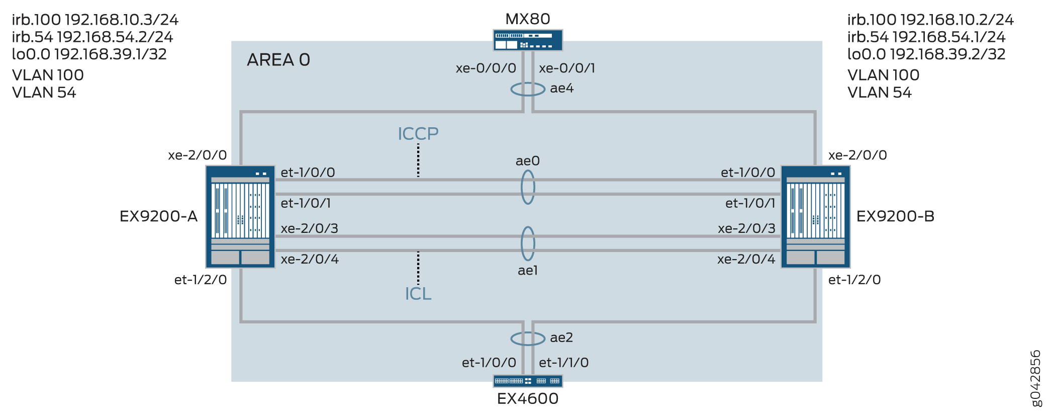
表 1 详细介绍了此配置示例中使用的拓扑。
| 主机名 | 基本硬件 | Multichassis 链路聚合组 |
|---|---|---|
| EX9200-A EX9200-B |
EX9200 EX9200 |
ae0 配置为聚合以太网接口,用作 ICCP 链路。以下接口属于 ae0 的一部分:EX9200-A 上的 et-1/0/0 和 et-1/0/1,EX9200-B 上的 et-1/0/0 和 et-1/0/1。 ae1 配置为聚合以太网接口并用作 ICL 链路,以下两个接口属于 ae1 :EX9200-A 上的 xe-2/0/3 和 xe-2/0/4,以及 EX9200-B 上的 xe-2/0/3 和 xe-2/0/4。 ae2 配置为 MC-LAG,以下接口属于 ae2: EX9200-A 上的 et-1/2/0 和 EX9200-B 上的 et-1/2/0。 ae4 配置为 MC-LAG,以下接口属于 ae4: EX9200-A 上的 xe-2/0/0 和 EX9200-B 上的 xe-2/0/0。 |
配置
CLI 快速配置
要快速配置此示例,请复制以下命令,将其粘贴到文本文件中,删除所有换行符,更改详细信息,以便与网络配置匹配,将命令复制并粘贴到层次结构级别的 [edit] CLI 中,然后从配置模式进入。commit
EX9200-A
set chassis aggregated-devices ethernet device-count 20
set interfaces et-1/0/0 ether-options 802.3ad ae0
set interfaces et-1/0/1 ether-options 802.3ad ae0
set interfaces et-1/2/0 ether-options 802.3ad ae2
set interfaces xe-2/0/3 hold-time up 100
set interfaces xe-2/0/3 hold-time down 9000
set interfaces xe-2/0/3 ether-options 802.3ad ae1
set interfaces xe-2/0/4 hold-time up 100
set interfaces xe-2/0/4 hold-time down 9000
set interfaces xe-2/0/4 ether-options 802.3ad ae1
set interfaces xe-2/0/0 ether-options 802.3ad ae4
set interfaces ae0 aggregated-ether-options lacp active
set interfaces ae0 aggregated-ether-options lacp periodic fast
set interfaces ae0 unit 0 family inet address 192.168.90.1/24
set interfaces ae1 description ICL-LINK
set interfaces ae1 aggregated-ether-options lacp active
set interfaces ae1 aggregated-ether-options lacp periodic fast
set interfaces ae1 unit 0 family ethernet-switching interface-mode trunk
set interfaces ae1 unit 0 family ethernet-switching vlan members all
set interfaces ae2 aggregated-ether-options lacp active
set interfaces ae2 aggregated-ether-options lacp periodic fast
set interfaces ae2 aggregated-ether-options lacp system-id 00:01:02:03:04:05
set interfaces ae2 aggregated-ether-options lacp admin-key 3
set interfaces ae2 aggregated-ether-options mc-ae mc-ae-id 3
set interfaces ae2 aggregated-ether-options mc-ae redundancy-group 1
set interfaces ae2 aggregated-ether-options mc-ae chassis-id 0
set interfaces ae2 aggregated-ether-options mc-ae mode active-active
set interfaces ae2 aggregated-ether-options mc-ae status-control active
set interfaces ae2 aggregated-ether-options mc-ae init-delay-time 520
set interfaces ae2 aggregated-ether-options mc-ae events iccp-peer-down prefer-status-control-active
set interfaces ae2 unit 0 family ethernet-switching interface-mode trunk
set interfaces ae2 unit 0 family ethernet-switching vlan members all
set interfaces ae4 aggregated-ether-options lacp active
set interfaces ae4 aggregated-ether-options lacp periodic fast
set interfaces ae4 aggregated-ether-options lacp system-id 00:01:02:03:04:06
set interfaces ae4 aggregated-ether-options lacp admin-key 7
set interfaces ae4 aggregated-ether-options mc-ae mc-ae-id 7
set interfaces ae4 aggregated-ether-options mc-ae redundancy-group 1
set interfaces ae4 aggregated-ether-options mc-ae chassis-id 0
set interfaces ae4 aggregated-ether-options mc-ae mode active-active
set interfaces ae4 aggregated-ether-options mc-ae status-control active
set interfaces ae4 aggregated-ether-options mc-ae init-delay-time 520
set interfaces ae4 aggregated-ether-options mc-ae events iccp-peer-down prefer-status-control-active
set interfaces ae4 unit 0 family ethernet-switching interface-mode trunk
set interfaces ae4 unit 0 family ethernet-switching vlan members v54
set vlans rack_1 vlan-id 100
set vlans rack_1 vlan-id 54
set vlans rack_1 l3-interface irb.100
set vlans v54 l3-interface irb.54
set interfaces irb unit 54 family inet address 192.168.54.2/24 arp 192.168.54.1 l2-interface ae1.0
set interfaces irb unit 54 family inet address 192.168.54.2/24 arp 192.168.54.1 mac 3c:8a:b0:85:78:70
set interfaces irb unit 100 family inet address 192.168.10.3/24 arp 192.168.10.2 l2-interface ae1.0
set interfaces irb unit 100 family inet address 192.168.10.3/24 arp 192.168.10.2 mac 3c:8a:b0:85:78:70
set interfaces lo0 unit 0 family inet address 192.168.39.1/32
set protocols iccp local-ip-addr 192.168.39.1
set protocols iccp peer 192.168.39.2 session-establishment-hold-time 50
set protocols iccp peer 192.168.39.2 redundancy-group-id-list 1
set protocols iccp peer 192.168.39.2 backup-liveness-detection backup-peer-ip 10.105.5.6
set protocols iccp peer 192.168.39.2 liveness-detection minimum-interval 2000
set protocols iccp peer 192.168.39.2 liveness-detection multiplier 4
set multi-chassis multi-chassis-protection 192.168.39.2 interface ae1
set switch-options service-id 1
EX9200-B
set chassis aggregated-devices ethernet device-count 20
set interfaces et-1/0/0 ether-options 802.3ad ae0
set interfaces et-1/0/1 ether-options 802.3ad ae0
set interfaces et-1/2/0 ether-options 802.3ad ae2
set interfaces xe-2/0/0 ether-options 802.3ad ae4
set interfaces xe-2/0/3 hold-time up 100
set interfaces xe-2/0/3 hold-time down 9000
set interfaces xe-2/0/3 ether-options 802.3ad ae1
set interfaces xe-2/0/4 hold-time up 100
set interfaces xe-2/0/4 hold-time down 9000
set interfaces xe-2/0/4 ether-options 802.3ad ae1
set interfaces ae0 aggregated-ether-options lacp active
set interfaces ae0 aggregated-ether-options lacp periodic fast
set interfaces ae0 unit 0 family inet address 192.168.90.2/24
set interfaces ae1 description ICL-LINK
set interfaces ae1 aggregated-ether-options lacp active
set interfaces ae1 aggregated-ether-options lacp periodic fast
set interfaces ae1 unit 0 family ethernet-switching interface-mode trunk
set interfaces ae1 unit 0 family ethernet-switching vlan members all
set interfaces ae2 aggregated-ether-options lacp active
set interfaces ae2 aggregated-ether-options lacp periodic fast
set interfaces ae2 aggregated-ether-options lacp system-id 00:01:02:03:04:05
set interfaces ae2 aggregated-ether-options lacp admin-key 3
set interfaces ae2 aggregated-ether-options mc-ae mc-ae-id 3
set interfaces ae2 aggregated-ether-options mc-ae redundancy-group 1
set interfaces ae2 aggregated-ether-options mc-ae chassis-id 1
set interfaces ae2 aggregated-ether-options mc-ae mode active-active
set interfaces ae2 aggregated-ether-options mc-ae init-delay-time 520
set interfaces ae2 aggregated-ether-options mc-ae events

set interfaces ae2 aggregated-ether-options mc-ae status-control standby
set interfaces ae2 unit 0 family ethernet-switching interface-mode trunk
set interfaces ae2 unit 0 family ethernet-switching vlan members all
set interfaces ae4 aggregated-ether-options lacp active
set interfaces ae4 aggregated-ether-options lacp periodic fast
set interfaces ae4 aggregated-ether-options lacp system-id 00:01:02:03:04:06
set interfaces ae4 aggregated-ether-options lacp admin-key 7
set interfaces ae4 aggregated-ether-options mc-ae mc-ae-id 7
set interfaces ae4 aggregated-ether-options mc-ae redundancy-group 1
set interfaces ae4 aggregated-ether-options mc-ae chassis-id 1
set interfaces ae4 aggregated-ether-options mc-ae mode active-active
set interfaces ae4 aggregated-ether-options mc-ae status-control standby
set interfaces ae4 aggregated-ether-options mc-ae init-delay-time 520
set interfaces ae4 unit 0 family ethernet-switching interface-mode trunk
set interfaces ae4 unit 0 family ethernet-switching vlan members v54
set vlans rack_1 vlan-id 100
set vlans rack_1 l3-interface irb.100
set vlans v54 vlan-id 54
set vlans v54 l3-interface irb.54
set interfaces irb unit 54 family inet address 192.168.54.1/24 arp 192.168.54.2 l2-interface ae1.0
set interfaces irb unit 54 family inet address 192.168.54.1/24 arp 192.168.54.2 mac 00:1f:12:b6:6f:f0
set interfaces irb unit 100 family inet address 192.168.10.2/24 arp 192.168.10.3 l2-interface ae1.0
set interfaces irb unit 100 family inet address 192.168.10.2/24 arp 192.168.10.3 mac 00:1f:12:b6:6f:f0
set interfaces lo0 unit 0 family inet address 192.168.39.2/32
set protocols iccp local-ip-addr 192.168.39.2
set protocols iccp peer 192.168.39.1 session-establishment-hold-time 50
set protocols iccp peer 192.168.39.1 redundancy-group-id-list 1
set protocols iccp peer 192.168.39.1 backup-liveness-detection backup-peer-ip 10.105.5.5
set protocols iccp peer 192.168.39.1 liveness-detection minimum-interval 2000
set protocols iccp peer 192.168.39.1 liveness-detection multiplier 4
set multi-chassis multi-chassis-protection 192.168.39.1 interface ae1
set switch-options service-id 1
在交换机 A 上配置 MC-LAG
分步程序
下面的示例要求您在各个配置层级中进行导航。
-
配置要在交换机 A 上创建的聚合以太网接口数量。
[edit chassis]
user@switch# set aggregated-devices ethernet device-count 20
-
将成员接口添加到将用于机箱间控制协议 (ICCP) 接口的聚合以太网接口。
[edit interfaces]
user@switch# set et-1/0/0 ether-options 802.3ad ae0
user@switch# set et-1/0/1 ether-options 802.3ad ae0
-
指定属于接口 ae2 的成员接口。
[edit interfaces]
user@switch# set et-1/2/0 ether-options 802.3ad ae2
-
使用高于配置的 BFD 计时器的保持时间值配置机箱之间链路 (ICL) 的成员接口,以防止在 ICCP 链路关闭之前将 ICL 播发为已关闭。
如果 ICL 在 ICCP 链路中断之前中断,则配置为备用状态控制对等方的 MC-LAG 接口将启动和关闭。接口上下移动会导致融合延迟。
[edit interfaces]
user@switch# set xe-2/0/3 hold-time up 100
user@switch# set xe-2/0/3 hold-time down 9000
user@switch# set xe-2/0/3 ether-options 802.3ad ae1
user@switch# set xe-2/0/4 hold-time up 100
user@switch# set xe-2/0/4 hold-time down 9000
user@switch# set xe-2/0/4 ether-options 802.3ad ae1
-
指定属于 ae4 的成员。
指定属于 ae4 的成员。
[edit interfaces]
user@switch# set xe-2/0/0 ether-options 802.3ad ae4
-
将 ae0 配置为第 3 层接口。
[edit interfaces]
user@switch# set ae0 aggregated-ether-options lacp active
user@switch# set ae0 aggregated-ether-options lacp periodic fast
user@switch# set ae0 unit 0 family inet address 192.168.90.1/24
-
将 ae1 配置为第 2 层接口。
[edit interfaces]
user@switch# set ae1 description ICL-LINK
user@switch# set ae1 aggregated-ether-options lacp active
user@switch# set ae1 aggregated-ether-options lacp periodic fast
-
在 EX9200-A 和 EX9200-B 之间配置中继接口。
[edit interfaces]
user@switch# set ae1 unit 0 family ethernet-switching interface-mode trunk
user@switch# set ae1 unit 0 family ethernet-switching vlan members all
-
在 ae2 上配置 LACP 参数。
[edit interfaces]
user@switch# set ae2 aggregated-ether-options lacp active
user@switch# set ae2 aggregated-ether-options lacp periodic fast
-
配置 LACP 系统 ID。
[edit interfaces]
user@switch# set ae2 aggregated-ether-options lacp system-id 00:01:02:03:04:06
-
配置 MC-AE 接口属性。
[edit interfaces]
user@switch# set ae2 aggregated-ether-options lacp admin-key 3
user@switch# set ae2 aggregated-ether-options mc-ae mc-ae-id 3
user@switch# set ae2 aggregated-ether-options mc-ae redundancy-group 1
-
为聚合以太网接口所属的 MC-LAG 指定唯一的机箱 ID。
[edit interfaces]
user@switch# set ae2 aggregated-ether-options mc-ae chassis-id 0
-
指定聚合以太网接口所属的 MC-LAG 模式。
[edit interfaces]
user@switch# set ae2 aggregated-ether-options mc-ae mode active-active
-
在托管 MC-LAG 的交换机上配置状态控制。
如果一台交换机处于活动模式,则另一台交换机必须处于备用模式。
[edit interfaces]
user@switch# set ae2 aggregated-ether-options mc-ae status-control active
-
指定必须形成路由邻接的时间(以秒为单位)。
[edit interfaces]
user@switch# set ae2 aggregated-ether-options mc-ae init-delay-time 520
-
指定如果 MC-LAG 组的对等方关闭,则配置为状态控制活动的对等方将成为活动对等方。
[edit interfaces]
user@switch# set ae2 aggregated-ether-options mc-ae events iccp-peer-down prefer-status-control-active
-
将 ae2 配置为具有所有 VLAN 成员资格的中继端口。
[edit interfaces]
user@switch# set ae2 unit 0 family ethernet-switching interface-mode trunk
user@switch# set ae2 unit 0 family ethernet-switching vlan members all
-
在 ae4 上配置 LACP 参数。
[edit interfaces]
user@switch# set ae4 aggregated-ether-options lacp active
user@switch# set ae4 aggregated-ether-options lacp periodic fast
-
指定 LACP 管理密钥。
[edit interfaces]
user@switch# set ae4 aggregated-ether-options lacp system-id 00:01:02:03:04:06
user@switch# set ae4 aggregated-ether-options lacp admin-key 7
user@switch# set ae4 aggregated-ether-options mc-ae mc-ae-id 7
user@switch# set ae4 aggregated-ether-options mc-ae redundancy-group 1
-
为聚合以太网接口所属的 MC-LAG 指定唯一的机箱 ID。
[edit interfaces]
user@switch# set ae4 aggregated-ether-options mc-ae chassis-id 0
user@switch# set ae4 aggregated-ether-options mc-ae mode active-active
-
在托管 MC-LAG 的交换机上配置状态控制。
如果一台交换机处于活动模式,则另一台交换机必须处于备用模式。
[edit interfaces]
user@switch# set ae4 aggregated-ether-options mc-ae status-control active
user@switch# set ae4 aggregated-ether-options mc-ae init-delay-time 520
user@switch# set ae4 aggregated-ether-options mc-ae events iccp-peer-down prefer-status-control-active
-
将 ae4 配置为第 2 层接口。
[edit interfaces]
user@switch# set ae4 unit 0 family ethernet-switching interface-mode trunk
user@switch# set ae4 unit 0 family ethernet-switching vlan members v54
-
配置 VLAN rack_1,并在 VLAN rack_1上配置第 3 层 IRB 接口。
[edit vlans]
user@switch# set rack_1 vlan-id 100
user@switch# set rack_1 l3-interface irb.100
-
配置 VLAN rack_1。
[edit vlans]
user@switch# set rack_1 vlan-id 54
-
配置 VLAN 54 并在 VLAN 54 上配置第 3 层 IRB。
[edit vlans]
user@switch# set v54 vlan-id 54
user@switch# set v54 l3-interface irb.54
-
在 VLAN 54 上配置 IRB 接口。
您必须在 MC-LAG 对等方上配置静态 ARP,以允许路由协议遍历 IRB 接口。
[edit interfaces]
user@switch# set irb unit 54 family inet address 192.168.54.2/24 arp 192.168.54.1 l2-interface ae1.0
user@switch# set irb unit 54 family inet address 192.168.54.2/24 arp 192.168.54.1 mac 3c:8a:b0:85:78:70
-
在 MC-LAG 对等方上配置静态 ARP,以允许路由协议遍历 IRB 接口
[edit interfaces]
user@switch# set irb unit 100 family inet address 192.168.10.3/24 arp 192.168.10.2 l2-interface ae1.0
user@switch# set irb unit 100 family inet address 192.168.10.3/24 arp 192.168.10.2 mac 3c:8a:b0:85:78:70
-
配置环路接口。
[edit interfaces]
user@switch# set lo0 unit 0 family inet address 192.168.39.2/32
-
使用环路地址配置 ICCP。
[edit protocols]
user@switch# set iccp local-ip-addr 192.168.39.1
-
配置会话建立保持时间,以便 ICCP 能够更快地连接。
[edit protocols]
user@switch# set iccp peer 192.168.39.2 session-establishment-hold-time 50
user@switch# set iccp peer 192.168.39.2 redundancy-group-id-list 1
user@switch# set iccp peer 192.168.39.2 backup-liveness-detection backup-peer-ip 10.105.5.6
-
要启用双向转发检测 (BFD),请配置最小接收间隔。
建议最小接收间隔值为 6 秒。
[edit protocols]
user@switch# set iccp peer 192.168.39.2 liveness-detection minimum-interval 2000
user@switch# set iccp peer 192.168.39.2 liveness-detection multiplier 4
[edit multi-chassis]
user@switch# set multi-chassis-protection 192.168.39.2 interface ae1
-
指定交换机服务 ID。
交换机服务 ID 用于跨 MC-LAG 成员同步应用、IGMP、ARP 和 MAC 学习。
[edit switch-options]
user@switch# set service-id 1
在交换机 B 上配置 MC-LAG
分步程序
下面的示例要求您在各个配置层级中进行导航。
-
配置要在交换机 A 上创建的聚合以太网接口数量。
[edit chassis]
user@switch# set aggregated-devices ethernet device-count 20
-
将成员接口添加到将用于机箱间控制协议 (ICCP) 接口的聚合以太网接口。
[edit interfaces]
user@switch# set et-1/0/0 ether-options 802.3ad ae0
user@switch# set et-1/0/1 ether-options 802.3ad ae0
-
指定属于接口 ae2 的成员接口。
[edit interfaces]
user@switch# set et-1/2/0 ether-options 802.3ad ae2
-
使用高于配置的 BFD 计时器的保持时间值配置机箱之间链路 (ICL) 的成员接口,以防止在 ICCP 链路关闭之前将 ICL 播发为已关闭。
如果 ICL 在 ICCP 链路中断之前中断,则配置为备用状态控制对等方的 MC-LAG 接口将启动和关闭。接口上下移动会导致融合延迟。
[edit interfaces]
user@switch# set xe-2/0/3 hold-time up 100
user@switch# set xe-2/0/3 hold-time down 9000
user@switch# set xe-2/0/3 ether-options 802.3ad ae1
user@switch# set xe-2/0/4 hold-time up 100
user@switch# set xe-2/0/4 hold-time down 9000
user@switch# set xe-2/0/4 ether-options 802.3ad ae1
-
指定属于 ae4 的成员。
[edit interfaces]
user@switch# set xe-2/0/0 ether-options 802.3ad ae4
-
将 ae0 配置为第 3 层接口。
[edit interfaces]
user@switch# set ae0 aggregated-ether-options lacp active
user@switch# set ae0 aggregated-ether-options lacp periodic fast
user@switch# set ae0 unit 0 family inet address 192.168.90.2/24
-
将 ae1 配置为第 2 层接口。
[edit interfaces]
user@switch# set ae1 description ICL-LINK
user@switch# set ae1 aggregated-ether-options lacp active
user@switch# set ae1 aggregated-ether-options lacp periodic fast
-
在 EX9200-A 和 EX9200-B 之间配置中继接口。
[edit interfaces]
user@switch# set ae1 unit 0 family ethernet-switching interface-mode trunk
user@switch# set ae1 unit 0 family ethernet-switching vlan members all
-
在 ae2 上配置 LACP 参数。
[edit interfaces]
user@switch# set ae2 aggregated-ether-options lacp active
user@switch# set ae2 aggregated-ether-options lacp periodic fast
-
配置 LACP 系统 ID。
[edit interfaces]
user@switch# set ae2 aggregated-ether-options lacp system-id 00:01:02:03:04:05
-
配置 MC-AE 接口属性。
[edit interfaces]
user@switch# set ae2 aggregated-ether-options lacp admin-key 3
user@switch# set ae2 aggregated-ether-options mc-ae mc-ae-id 3
user@switch# set ae2 aggregated-ether-options mc-ae redundancy-group 1
-
为聚合以太网接口所属的 MC-LAG 指定唯一的机箱 ID。
[edit interfaces]
user@switch# set ae2 aggregated-ether-options mc-ae chassis-id 1
-
指定聚合以太网接口所属的 MC-LAG 模式。
[edit interfaces]
user@switch# set ae2 aggregated-ether-options mc-ae mode active-active
-
指定必须形成路由邻接的时间(以秒为单位)。
[edit interfaces]
user@switch# set ae2 aggregated-ether-options mc-ae init-delay-time 520
-
在托管 MC-LAG 的交换机上配置状态控制。
如果一台交换机处于活动模式,则另一台交换机必须处于备用模式。
[edit interfaces]
user@switch# set ae2 aggregated-ether-options mc-ae status-control standby
-
将 ae2 配置为具有所有 VLAN 成员资格的中继端口。
[edit interfaces]
user@switch# set ae2 unit 0 family ethernet-switching interface-mode trunk
user@switch# set ae2 unit 0 family ethernet-switching vlan members all
-
在 ae4 上配置 LACP 参数。
[edit interfaces]
user@switch# set ae4 aggregated-ether-options lacp active
user@switch# set ae4 aggregated-ether-options lacp periodic fast
-
指定 LACP 管理密钥。
[edit interfaces]
user@switch# set ae4 aggregated-ether-options lacp system-id 00:01:02:03:04:06
user@switch# set ae4 aggregated-ether-options lacp admin-key 7
user@switch# set ae4 aggregated-ether-options mc-ae mc-ae-id 7
user@switch# set ae4 aggregated-ether-options mc-ae redundancy-group 1
-
为聚合以太网接口所属的 MC-LAG 指定唯一的机箱 ID。
[edit interfaces]
user@switch# set ae4 aggregated-ether-options mc-ae chassis-id 1
user@switch# set ae4 aggregated-ether-options mc-ae mode active-active
-
在托管 MC-LAG 的交换机上配置状态控制。
如果一台交换机处于活动模式,则另一台交换机必须处于备用模式。
[edit interfaces]
user@switch# set ae4 aggregated-ether-options mc-ae status-control standby
user@switch# set ae4 aggregated-ether-options mc-ae init-delay-time 520
user@switch# set ae4 aggregated-ether-options mc-ae events iccp-peer-down prefer-status-control-active
-
将 ae4 配置为第 2 层接口。
[edit interfaces]
user@switch# set ae4 unit 0 family ethernet-switching interface-mode trunk
user@switch# set ae4 unit 0 family ethernet-switching vlan members v54
-
配置 VLAN rack_1,并在 VLAN rack_1上配置第 3 层 IRB 接口。
[edit vlans]
user@switch# set rack_1 vlan-id 100
user@switch# set rack_1 l3-interface irb.100
-
配置 VLAN 54 并在 VLAN 54 上配置 IRB。
[edit vlans]
user@switch# set v54 vlan-id 54
user@switch# set v54 l3-interface irb.54
-
在 MC-LAG 对等方上配置静态 ARP,以允许路由协议遍历 IRB 接口。
[edit interfaces]
user@switch# set irb unit 54 family inet address 192.168.54.1/24 arp 192.168.54.2 l2-interface ae1.0
user@switch# set irb unit 54 family inet address 192.168.54.1/24 arp 192.168.54.2 mac mac 00:1f:12:b6:6f:f0
-
在 MC-LAG IRB 对等方上配置静态地址解析协议 (ARP),以允许路由协议遍历 IRB 接口。
[edit interfaces]
user@switch# set irb unit 100 family inet address 192.168.10.2/24 arp 192.168.10.3 l2-interface ae1.0
user@switch# set irb unit 100 family inet address 192.168.10.2/24 arp 192.168.10.3 mac 00:1f:12:b6:6f:f0
-
配置环路接口。
[edit interfaces]
user@switch# set lo0 unit 0 family inet address 192.168.39.2/32
-
使用环路地址配置 ICCP。
[edit protocols]
user@switch# set iccp local-ip-addr 192.168.39.2
-
配置会话建立保持时间,以便 ICCP 能够更快地连接。
[edit protocols]
user@switch# set iccp peer 192.168.39.1 session-establishment-hold-time 50
user@switch# set iccp peer 192.168.39.1 redundancy-group-id-list 1
user@switch# set iccp peer 192.168.39.1 backup-liveness-detection backup-peer-ip 10.105.5.5
-
要启用双向转发检测 (BFD),请配置最小接收间隔。
建议最小接收间隔值为 6 秒。
[edit protocols]
user@switch# set iccp peer 192.168.39.1 liveness-detection minimum-interval 2000
user@switch# set iccp peer 192.168.39.1 liveness-detection multiplier 4
[edit multi-chassis]
user@switch# set multi-chassis-protection 192.168.39.1 interface ae1
-
指定交换机服务 ID。
交换机服务 ID 用于跨 MC-LAG 成员同步应用、IGMP、ARP 和 MAC 学习。
[edit switch-options]
user@switch# set service-id 1
结果
显示 EX9200-A 上的配置结果。
user@switch> show chassis
    chassis {
        redundancy {
            graceful-switchover;
        }
        aggregated-devices {
            ethernet {
                device-count 20;
            }
        }
    }
user@switch> show interfaces
    interfaces {
        et-1/0/0 {
            ether-options {
                802.3ad ae0;
            }
        }
        et-1/0/1 {
            ether-options {
                802.3ad ae0;
            }
        }
        et-1/2/0 {
            ether-options {
                802.3ad ae2;
            }
        }
        xe-2/0/3 {
            hold-time up 100 down 7000;
            ether-options {
                802.3ad ae1;
            }
        }
        xe-2/0/4 {
            hold-time up 100 down 7000;
            ether-options {
                802.3ad ae1;
            }
        }
        ae0 {
            aggregated-ether-options {
                lacp {
                    active;
                    periodic fast;
                }
            }
            unit 0 {
                family inet {
                    address 192.168.90.1/24;
                }
            }
        }
        ae1 {
            description ICL-LINK;
            aggregated-ether-options {
                lacp {
                    active;
                    periodic fast;
                }
            }
            unit 0 {
                family ethernet-switching {
                    interface-mode trunk;
                    vlan {
                        members all;
                    }
                }
            }
        }
        ae2 {
            aggregated-ether-options {
                lacp {
                    active;
                    periodic fast;
                    system-id 00:01:02:03:04:05;
                    admin-key 3;
                }
                mc-ae {
                    mc-ae-id 3;
                    redundancy-group 1;
                    chassis-id 0;
                    mode active-active;
                    status-control active;
                    init-delay-time 520;
                    events {
                        iccp-peer-down {
                            prefer-status-control-active;
                        }
                    }
                }
            }
            unit 0 {
                family ethernet-switching {
                    interface-mode trunk;
                    vlan {
                        members all;
                    }
                }
            }
        }
        ae4 {
            aggregated-ether-options {
                lacp {
                    active;
                    periodic fast;
                    system-id 00:01:02:03:04:06;
                    admin-key 7;
                }
                mc-ae {
                    mc-ae-id 7;
                    redundancy-group 1;
                    chassis-id 0;
                    mode active-active;
                    status-control standby;
                    init-delay-time 520;
                    events {
                        iccp-peer-down {
                            prefer-status-control-active;
                        }
                    }
                }
            }
                unit 0 {
                    family ethernet-switching {
                        interface-mode trunk;
                        vlan {
                            members [ rack_1 v54 ];
                        }
                    }
            irb {
                arp-l2-validate;
                    unit 54 {
                        family inet {
                            address 192.168.54.2/24 {
                                arp 192.168.54.1 l2-interface ae1.0 mac 3c:8a:b0:85:78:70;
                            }
                        }
                    }
                        unit 100 {
                            family inet {
                                address 192.168.10.3/24 {
                                    arp 192.168.10.2 l2-interface ae1.0 mac 3c:8a:b0:85:78:70;
                                }
                            }
                        }
                }
                lo0 {
                    unit 0 {
                        family inet {
                            address 192.168.39.1/32;
                        }
                    }
                }
user@switch> show multi-chassis
    multi-chassis {
        multi-chassis-protection 192.168.39.2 {
            interface ae1;
        }
    }
user@switch> show protocols
    protocols {
        iccp {
            local-ip-addr 192.168.39.1;
            peer 192.168.39.2 {
                session-establishment-hold-time 50;
                redundancy-group-id-list 1;
                backup-liveness-detection {
                    backup-peer-ip 10.105.5.6;
                }
                liveness-detection {
                    minimum-interval 2000;
                    multiplier 3;
                }
            }
        }
        lldp {
            interface all;
        }
        layer2-control {
            nonstop-bridging;
        }
    }
user@switch> show switch-options
    switch-options {
        service-id 1;
    }
user@switch> show vlans
    vlans {
        rack_1 {
            vlan-id 100;
            l3-interface irb.100;

        }
            v54 {
                vlan-id 54;
                l3-interface irb.54;
            }
        }
显示 EX9200-B 上的配置结果。
user@switch> show chassis
    chassis {
        redundancy {
            graceful-switchover;
        }
        aggregated-devices {
            ethernet {
                device-count 20;
            }
        }
    }
user@switch> show interfaces
    interfaces {
        et-1/0/0 {
            ether-options {
                802.3ad ae0;
            }
        }
        et-1/0/1 {
            ether-options {
                802.3ad ae0;
            }
        }
        et-1/2/0 {
            ether-options {
                802.3ad ae2;
            }
        }
        xe-2/0/3 {
            hold-time up 100 down 7000;
            ether-options {
                802.3ad ae1;
            }
        }
        xe-2/0/4 {
            hold-time up 100 down 7000;
            ether-options {
                802.3ad ae1;
            }
        }
        ae0 {
            aggregated-ether-options {
                lacp {
                    active;
                    periodic fast;
                }
            }
                unit 0 {
                    family inet {
                    address 192.168.90.2/24;
                }
        }
        ae1 {
            description ICL-LINK;
            aggregated-ether-options {
                lacp {
                    active;
                    periodic fast;
                }
            }
            unit 0 {
                family ethernet-switching {
                    interface-mode trunk;
                    vlan {
                        members all;
                    }
                }
            }
        }
        ae2 {
            aggregated-ether-options {
                lacp {
                    active;
                    periodic fast;
                    system-id 00:01:02:03:04:05;
                    admin-key 3;
                }
                mc-ae {
                    mc-ae-id 3;
                    redundancy-group 1;
                    chassis-id 1;
                    mode active-active;
                    status-control active;
                    init-delay-time 520;
                    events {
                        iccp-peer-down {
                            prefer-status-control-active;
                        }
                    }
                }
            }
            unit 0 {
                family ethernet-switching {
                    interface-mode trunk;
                    vlan {
                        members all;
                    }
                }
            }
        }
        ae4 {
            aggregated-ether-options {
                lacp {
                    active;
                    periodic fast;
                    system-id 00:01:02:03:04:06;
                    admin-key 7;
                }
                mc-ae {
                    mc-ae-id 7;
                    redundancy-group 1;
                    chassis-id 1;
                    mode active-active;
                    status-control standby;
                    init-delay-time 520;
                }
            }
                unit 0 {
                    family ethernet-switching {
                        interface-mode trunk;
                        vlan {
                            members [rack_1 v54 ];
                        }
                    }
            irb {
            arp-l2-validate;
                unit 54 {
                    family inet {
                        address 192.168.54.1/24 {
                            arp 192.168.54.2 l2-interface ae1.0 mac 00:1f:12:b6:6f:f0;
                        }
                    }
                }
                    unit 100 {
                        family inet {
                            address 192.168.10.2/24 {
                                arp 192.168.10.3 l2-interface ae1.0 mac 00:1f:12:b6:6f:f0;
                            }
                        }
                    }
            lo0 {
                    unit 0 {
                        family inet {
                            address 192.168.39.2/32;
                        }
                    }
user@switch> show multi-chassis
    multi-chassis {
        multi-chassis-protection 192.168.39.1 {
            interface ae1;
        }
    }
user@switch> show protocols
    protocols {
        iccp {
            local-ip-addr 192.168.39.2;
            peer 192.168.39.1 {
                session-establishment-hold-time 50;
                redundancy-group-id-list 1;
                backup-liveness-detection {
                    backup-peer-ip 10.105.5.5;
                }
                liveness-detection {
                    minimum-interval 2000;
                    multiplier 3;
                }
            }
        }
        lldp {
            interface all;
        }
        layer2-control {
            nonstop-bridging;
        }
    }
user@switch> show switch-options
    switch-options {
        service-id 1;
    }
user@switch> show vlans
    vlans {
            rack_1 {
                vlan-id 100;
                l3-interface irb.100;

            }
            v54 {
                vlan-id 54;
                l3-interface irb.54;
            }
        }
(选答)配置 RSTP
CLI 快速配置
交换机 A 和交换机 B
set protocols rstp interface ae2
set protocols rstp interface ae4
set protocols rstp system-identifier 00:01:02:03:04:05
set protocols rstp bridge-priority 0
配置交换机 A 和交换机 B
分步程序
下面的示例要求您在各个配置层级中进行导航。有关导航 CLI 的信息,请参阅 在 配置模式下使用 CLI 编辑器 。
要配置交换机 A 和交换机 B,请执行以下操作:
-
在 ae2 和 ae4 接口上启用快速生成树协议,以实现可选的环路防御。
[edit protocols]
user@switch# set rstp interface ae2
user@switch# set rstp interface ae4
-
配置系统标识符。
[edit protocols]
user@switch# set rstp system-identifier 00:01:02:03:04:05
-
将快速生成树协议优先级设置为 0。这将使 MC-AE 节点成为最高优先级。
[edit protocols]
user@switch# set rstp bridge-priority 0
交换机 A 和交换机 B
在配置模式下,输入 show protocols rstp 命令以确认您的配置。如果输出未显示预期的配置,请重复此示例中的说明以更正配置。
user@switch> show protocols rstp
rstp {
system-identifier 00:01:02:03:04:05;
interface ae2;
interface ae4;
}
(选答)配置 IGMP 侦听
CLI 快速配置
交换机 A 和交换机 B
set protocols igmp-snooping vlan rack_1 set protocols igmp-snooping vlan v54 set multicast-snooping-options multichassis-lag-replicate-state set protocols igmp-snooping vlan rack_1 interface ae1.0 multicast-router-interface set protocols igmp-snooping vlan v54 interface ae1.0 multicast-router-interface
配置交换机 A 和交换机 B
分步程序
下面的示例要求您在各个配置层级中进行导航。有关导航 CLI 的信息,请参阅 在 配置模式下使用 CLI 编辑器 。
要配置交换机 A 和交换机 B,请执行以下操作:
-
为所有 VLAN 启用 IGMP 侦听。
[edit protocols] user@switch# set igmp-snooping vlan rack_1 user@switch# set igmp-snooping vlan v54
-
配置网桥域时,在 MC-LAG 对等方之间同步组播状态。
在全局级别,IGMP 加入和离开消息从 MC-LAG 接口活动链路复制到备用链路,以便在故障切换后更快地恢复成员信息。
[edit multicast-snooping-options] user@switch# set multichassis-lag-replicate-state
-
将 ICL-PL 接口配置为面向路由器的接口。
[edit protocols] user@switch# set igmp-snooping vlan rack_1 interface ae1.0 multicast-router-interface user@switch# set igmp-snooping vlan v54 interface ae1.0 multicast-router-interface
交换机 A 和交换机 B
在配置模式下,输入和show protocols igmpshow multicast-snooping-options命令以确认您的配置。如果输出未显示预期的配置,请重复此示例中的说明以更正配置。
user@switch> show protocols igmp
igmp-snooping {
vlan rack_1 {
interface ae1.0 {
multicast-router-interface;
}
}
vlan v54 {
interface ae1.0 {
multicast-router-interface;
}
}
}
user@switch> show multicast-snooping-options
multicast-snooping-options {
multichassis-lag-replicate-state;
}
(选答)配置 VRRP
您不能同时配置 VRRP 和 MAC 地址同步。
CLI 快速配置
开关 A
set interfaces irb unit 100 family inet address 192.168.10.3/24 vrrp-group 1 virtual-address 192.168.10.1 set interfaces irb unit 100 family inet address 192.168.10.3/24 vrrp-group 1 priority 150 set interfaces irb unit 100 family inet address 192.168.10.3/24 vrrp-group 1 accept-data set interfaces irb unit 54 family inet address 192.168.54.2/24 vrrp-group 4 virtual-address 192.168.54.3 set interfaces irb unit 54 family inet address 192.168.54.2/24 vrrp-group 4 priority 200
开关 B
set interfaces irb unit 100 family inet address 192.168.10.2/24 vrrp-group 1 virtual-address 192.168.10.1 set interfaces irb unit 100 family inet address 192.168.10.2/24 vrrp-group 1 priority 200 set interfaces irb unit 100 family inet address 192.168.10.2/24 vrrp-group 1 accept-data set interfaces irb unit 54 family inet address 192.168.54.1/24 vrrp-group 4 virtual-address 192.168.54.3 set interfaces irb unit 54 family inet address 192.168.54.1/24 vrrp-group 4 priority 150
配置交换机 A
分步程序
下面的示例要求您在各个配置层级中进行导航。有关导航 CLI 的信息,请参阅 在 配置模式下使用 CLI 编辑器 。
要配置交换机 A:
-
通过为每个 MC-LAG 创建 IRB 接口,在 MC-LAG 上启用 VRRP,分配一个在 VRRP 组中的每台交换机之间共享的虚拟 IP 地址,并为 VRRP 组中的每个成员分配一个单独的 IP 地址。
[edit interfaces] user@switch# set irb unit 100 family inet address 192.168.10.3/24 vrrp-group 1 virtual-address 192.168.10.1 user@switch# set irb unit 100 family inet address 192.168.10.3/24 vrrp-group 1 priority 150 user@switch# set irb unit 100 family inet address 192.168.10.3/24 vrrp-group 1 accept-data
-
通过为每个 MC-LAG 创建 IRB 接口,在 MC-LAG 上启用 VRRP,分配一个在 VRRP 组中的每台交换机之间共享的虚拟 IP 地址,并为 VRRP 组中的每个成员分配一个单独的 IP 地址。
[edit interfaces] user@switch# set irb unit 54 family inet address 192.168.54.2/24 vrrp-group 4 virtual-address 192.168.54.3 user@switch# set irb unit 54 family inet address 192.168.54.2/24 vrrp-group 4 priority 200
开关 A
在配置模式下,输入和show interfaces irb unit 100 family inet address 192.168.10.3/24 vrrp-groupshow interfaces irb unit 100 family inet address 192.168.54.2/24 vrrp-group命令以确认您的配置。如果输出未显示预期的配置,请重复此示例中的说明以更正配置。
user@switch> show interfaces irb unit 100 family inet address 192.168.10.3/24 vrrp-group
vrrp-group 1 {
virtual-address 192.168.10.1;
priority 150;
accept-data;
}
user@switch> show interfaces irb unit 100 family inet address 192.168.54.2/24 vrrp-group
vrrp-group 4 {
virtual-address 192.168.54.3;
priority 150;
}
配置交换机 B
分步程序
下面的示例要求您在各个配置层级中进行导航。有关导航 CLI 的信息,请参阅 在 配置模式下使用 CLI 编辑器 。
要配置交换机 A:
-
通过为每个 MC-LAG 创建 IRB 接口,在 MC-LAG 上启用 VRRP,分配一个在 VRRP 组中的每台交换机之间共享的虚拟 IP 地址,并为 VRRP 组中的每个成员分配一个单独的 IP 地址。
[edit interfaces] user@switch# set irb unit 100 family inet address 192.168.10.2/24 vrrp-group 1 virtual-address 192.168.10.1 user@switch# set irb unit 100 family inet address 192.168.10.2/24 vrrp-group 1 priority 150 user@switch# set irb unit 100 family inet address 192.168.10.2/24 vrrp-group 1 accept-data
-
通过为每个 MC-LAG 创建 IRB 接口,在 MC-LAG 上启用 VRRP,分配一个在 VRRP 组中的每台交换机之间共享的虚拟 IP 地址,并为 VRRP 组中的每个成员分配一个单独的 IP 地址。
[edit interfaces] user@switch# set irb unit 54 family inet address 192.168.54.1/24 vrrp-group 4 virtual-address 192.168.54.3 user@switch# set irb unit 54 family inet address 192.168.54.1/24 vrrp-group 4 priority 150
开关 B
在配置模式下,输入 show protocols rstp 命令以确认您的配置。如果输出未显示预期的配置,请重复此示例中的说明以更正配置。
user@switch> show interfaces irb unit 100 family inet address 192.168.10.2/24 vrrp-group
vrrp-group 1 {
virtual-address 192.168.10.1;
priority 200;
accept-data;
}
user@switch> show interfaces irb unit 100 family inet address 192.168.54.1/24 vrrp-group
vrrp-group 4 {
virtual-address 192.168.54.3;
priority 150;
}
(选答)配置 MAC 地址同步
您不能同时配置 MAC 同步和 VRRP。
您必须在两个 MC-LAG 对等方的 VLAN 中的 IRB 接口上配置相同的 IP 地址。
CLI 快速配置
交换机 A 和交换机 B
set vlans v100 mcae-mac-synchronize set vlans v54 mcae-mac-synchronize
配置交换机 A 和交换机 B
分步程序
下面的示例要求您在各个配置层级中进行导航。有关导航 CLI 的信息,请参阅 在 配置模式下使用 CLI 编辑器 。
要配置交换机 A:
-
在交换机 A 和交换机 B 上的 MC-LAG VLAN 中配置 MAC 地址同步。
[edit] user@switch# set vlans v100 mcae-mac-synchronize [edit] user@switch# set vlans v54 mcae-mac-synchronize
交换机 A 和交换机 B
在配置模式下,输入和show vlans v100show vlans v54命令以确认您的配置。如果输出未显示预期的配置,请重复此示例中的说明以更正配置。
user@switch> show vlans v100
v100 {
vlan-id 100;
l3-interface irb.100;
mcae-mac-synchronize;
}
user@switch> show vlans v54
v54 {
vlan-id 54;
l3-interface irb.54;
mcae-mac-synchronize;
}
(选答)配置 OSPF
CLI 快速配置
交换机 A 和交换机 B
set protocols ospf area 0.0.0.0 interface lo0.0 set protocols ospf area 0.0.0.0 interface ae0.0 set protocols ospf area 0.0.0.0 interface irb.54 set protocols ospf area 0.0.0.0 interface irb.100
配置交换机 A 和交换机 B
分步程序
下面的示例要求您在各个配置层级中进行导航。有关导航 CLI 的信息,请参阅 在 配置模式下使用 CLI 编辑器 。
要配置交换机 A 和交换机 B,请执行以下操作:
-
配置 OSPF 区域。
[edit protocols] user@switch# set ospf area 0.0.0.0 interface lo0.0 user@switch# set ospf area 0.0.0.0 interface ae0.0 user@switch# set ospf area 0.0.0.0 interface irb.54 user@switch# set ospf area 0.0.0.0 interface irb.100
交换机 A 和交换机 B
在配置模式下,输入 show protocols ospf 命令以确认您的配置。如果输出未显示预期的配置,请重复此示例中的说明以更正配置。
user@switch> show protocols ospf
ospf {
area 0.0.0.0 {
interface lo0.0;
interface ae0.0;
interface irb.54;
interface irb.100;
}
}
(选答)配置 PIM
CLI 快速配置
开关 A
set protocols pim interface irb.54 set protocols pim interface irb.100 set protocols pim interface lo0.0 set protocols pim rp bootstrap-priority 150 set protocols pim rp local address 192.168.39.1
开关 B
set protocols pim interface irb.54 set protocols pim interface irb.100 set protocols pim interface lo0.0 set protocols pim rp bootstrap-priority 200 set protocols pim rp local address 192.168.39.2
配置交换机 A
分步程序
下面的示例要求您在各个配置层级中进行导航。有关导航 CLI 的信息,请参阅 在 配置模式下使用 CLI 编辑器 。
要配置交换机 A:
-
将协议无关组播 (PIM) 配置为组播协议。
[edit protocols] user@switch# set pim interface irb.54 user@switch# set pim interface irb.100
-
配置环路接口。
[edit protocols] user@switch# set pim interface lo0.0
-
将交换机配置为辅助汇聚点 (RP)。
较低优先级设置表示辅助 RP 处于自举配置中。
[edit protocols] user@switch# set pim rp bootstrap-priority 150 user@switch# set pim rp local address 192.168.39.1
开关 A
在配置模式下,输入 show protocols pim 命令以确认您的配置。如果输出未显示预期的配置,请重复此示例中的说明以更正配置。
user@switch> show protocols pim
pim {
rp {
bootstrap-priority 150;
local {
address 192.168.39.1;
}
}
interface irb.54;
interface irb.100;
interface lo0.0;
}
配置交换机 B
分步程序
下面的示例要求您在各个配置层级中进行导航。有关导航 CLI 的信息,请参阅 在 配置模式下使用 CLI 编辑器 。
要配置交换机 A:
-
将协议无关组播 (PIM) 配置为组播协议。
[edit protocols] user@switch# set pim interface irb.54 user@switch# set pim interface irb.100
-
配置环路接口。
[edit protocols] user@switch# set pim interface lo0.0
-
将交换机配置为辅助汇聚点 (RP)。
较低优先级设置表示辅助 RP 处于自举配置中。
[edit protocols] user@switch# set pim rp bootstrap-priority 200 user@switch# set pim rp local address 192.168.39.2
开关 B
在配置模式下,输入 show protocols pim 命令以确认您的配置。如果输出未显示预期的配置,请重复此示例中的说明以更正配置。
user@switch> show protocols pim
pim {
rp {
bootstrap-priority 200;
local {
address 192.168.39.2;
}
}
interface irb.54;
interface irb.100;
interface lo0.0;
}
(选答)配置 DHCP 中继
CLI 快速配置
交换机 A 和交换机 B
set forwarding-options dhcp-relay forward-snooped-clients all-interfaces set forwarding-options dhcp-relay overrides allow-snooped-clients set forwarding-options dhcp-relay server-group GVP-DHCP 10.105.5.202 set forwarding-options dhcp-relay active-server-group GVP-DHCP set forwarding-options dhcp-relay route-suppression destination set forwarding-options dhcp-relay group Floor1 interface irb.100 set forwarding-options dhcp-relay relay-option-82 circuit-id use-interface-description device
配置交换机 A 和交换机 B
分步程序
下面的示例要求您在各个配置层级中进行导航。有关导航 CLI 的信息,请参阅 在 配置模式下使用 CLI 编辑器 。
要配置交换机 A 和交换机 B,请执行以下操作:
-
在所有接口上配置正向侦听单播数据包。
[edit fowarding-options] user@switch# set dhcp-relay forward-snooped-clients all-interfaces
-
创建窥探单播客户端的绑定条目。
[edit forwarding-options] user@switch# set dhcp-relay overrides allow-snooped-clients
-
创建 DHCP 服务器组。
[edit forwarding-options] user@switch# set dhcp-relay server-group GVP-DHCP 10.105.5.202
-
将 DHCP 中继代理配置应用于指定的 DHCP 服务器地址组。
[edit forwarding-options] user@switch# set dhcp-relay active-server-group GVP-DHCP
-
配置中继代理以抑制安装相应客户端绑定的 ARP 和路由条目。
[edit forwarding-options] user@switch# set dhcp-relay route-suppression destination
-
创建至少包含一个接口的 DHCP 中继组。
DHCP 在 DHCP 组中定义的接口上运行。
[edit forwarding-options] user@switch# set dhcp-relay group Floor1 interface irb.100
-
使用选项 82 配置 DHCP 中继。
[edit forwarding-options] user@switch# set dhcp-relay relay-option-82 circuit-id use-interface-description device
交换机 A 和交换机 B
在配置模式下,输入 show protocols pim 命令以确认您的配置。如果输出未显示预期的配置,请重复此示例中的说明以更正配置。
user@switch> show forwarding-options dhcp-relay
dhcp-relay {
forward-snooped-clients all-interfaces;
overrides {
allow-snooped-clients;
}
relay-option-82 {
circuit-id {
use-interface-description device;
}
}
server-group {
GVP-DHCP {
10.105.5.202;
}
}
active-server-group GVP-DHCP;
route-suppression {
destination;
}
group Floor1 {
interface irb.100;
}
}
验证
确认配置工作正常。
- 验证 MC-LAG 上的 ICCP
- 验证 MC-LAG 上的 LACP
- 验证 MC-LAG 中的聚合以太网接口
- 验证 MC-LAG 上的 MAC 学习
- 验证 MC-LAG 中的 VRRP
- 验证 MC-LAG 上的 OSPF
验证 MC-LAG 上的 ICCP
目的
验证 ICCP 是否在 MC-LAG 中的每台设备上运行。
行动
-
验证交换机 A 上是否正在运行 ICCP。
root@EX92000-A> show iccp Redundancy Group Information for peer 192.168.39.2 TCP Connection : Established Liveliness Detection : Up Backup liveness peer status: Up Redundancy Group ID Status 1 Up Client Application: l2ald_iccpd_client Redundancy Group IDs Joined: 1 Client Application: lacpd Redundancy Group IDs Joined: 1 Client Application: MCSNOOPD Redundancy Group IDs Joined: 1 -
验证交换机 B 上是否正在运行 ICCP。
root@EX9200-B> show iccp Redundancy Group Information for peer 192.168.39.1 TCP Connection : Established Liveliness Detection : Up Backup liveness peer status: Up Redundancy Group ID Status 1 Up Client Application: lacpd Redundancy Group IDs Joined: 1 Client Application: l2ald_iccpd_client Redundancy Group IDs Joined: 1 Client Application: MCSNOOPD Redundancy Group IDs Joined: 1
意义
此输出显示,托管 MC-LAG 的对等方之间的 TCP 连接已开启,活度检测已开启,并且 MCSNOOPD 和 ESWD 客户端应用程序正在运行。
验证 MC-LAG 上的 LACP
目的
验证 LACP 是否在 MC-LAG 中的每台设备上正常工作。
行动
-
验证交换机 A 上的 LACP 接口是否已启动并运行。
root@EX9200-A> show lacp interfaces Aggregated interface: ae0 LACP state: Role Exp Def Dist Col Syn Aggr Timeout Activity et-1/0/0 Actor No No Yes Yes Yes Yes Fast Active et-1/0/0 Partner No No Yes Yes Yes Yes Fast Active et-1/0/1 Actor No No Yes Yes Yes Yes Fast Active et-1/0/1 Partner No No Yes Yes Yes Yes Fast Active LACP protocol: Receive State Transmit State Mux State et-1/0/0 Current Fast periodic Collecting distributing et-1/0/1 Current Fast periodic Collecting distributing Aggregated interface: ae1 LACP state: Role Exp Def Dist Col Syn Aggr Timeout Activity xe-2/0/3 Actor No No Yes Yes Yes Yes Fast Active xe-2/0/3 Partner No No Yes Yes Yes Yes Fast Active xe-2/0/4 Actor No No Yes Yes Yes Yes Fast Active xe-2/0/4 Partner No No Yes Yes Yes Yes Fast Active LACP protocol: Receive State Transmit State Mux State xe-2/0/3 Current Fast periodic Collecting distributing xe-2/0/4 Current Fast periodic Collecting distributing Aggregated interface: ae3 LACP state: Role Exp Def Dist Col Syn Aggr Timeout Activity xe-2/0/1 Actor No No Yes Yes Yes Yes Fast Active xe-2/0/1 Partner No No Yes Yes Yes Yes Fast Passive xe-2/0/2 Actor No No Yes Yes Yes Yes Fast Active xe-2/0/2 Partner No No Yes Yes Yes Yes Fast Passive LACP protocol: Receive State Transmit State Mux State xe-2/0/1 Current Fast periodic Collecting distributing xe-2/0/2 Current Fast periodic Collecting distributing Aggregated interface: ae4 LACP state: Role Exp Def Dist Col Syn Aggr Timeout Activity xe-2/0/0 Actor No No Yes Yes Yes Yes Fast Active xe-2/0/0 Partner No No Yes Yes Yes Yes Fast Active LACP protocol: Receive State Transmit State Mux State xe-2/0/0 Current Fast periodic Collecting distributing -
验证交换机 B 上的 LACP 接口是否已启动且运行。
root@EX9200-B> show lacp interfaces Aggregated interface: ae0 LACP state: Role Exp Def Dist Col Syn Aggr Timeout Activity et-1/0/0 Actor No No Yes Yes Yes Yes Fast Active et-1/0/0 Partner No No Yes Yes Yes Yes Fast Active et-1/0/1 Actor No No Yes Yes Yes Yes Fast Active et-1/0/1 Partner No No Yes Yes Yes Yes Fast Active LACP protocol: Receive State Transmit State Mux State et-1/0/0 Current Fast periodic Collecting distributing et-1/0/1 Current Fast periodic Collecting distributing Aggregated interface: ae1 LACP state: Role Exp Def Dist Col Syn Aggr Timeout Activity xe-2/0/3 Actor No No Yes Yes Yes Yes Fast Active xe-2/0/3 Partner No No Yes Yes Yes Yes Fast Active xe-2/0/4 Actor No No Yes Yes Yes Yes Fast Active xe-2/0/4 Partner No No Yes Yes Yes Yes Fast Active LACP protocol: Receive State Transmit State Mux State xe-2/0/3 Current Fast periodic Collecting distributing xe-2/0/4 Current Fast periodic Collecting distributing Aggregated interface: ae2 LACP state: Role Exp Def Dist Col Syn Aggr Timeout Activity et-1/2/0 Actor No No Yes Yes Yes Yes Fast Active et-1/2/0 Partner No No Yes Yes Yes Yes Fast Passive LACP protocol: Receive State Transmit State Mux State et-1/2/0 Current Fast periodic Collecting distributing Aggregated interface: ae4 LACP state: Role Exp Def Dist Col Syn Aggr Timeout Activity xe-2/0/0 Actor No No Yes Yes Yes Yes Fast Active xe-2/0/0 Partner No No Yes Yes Yes Yes Fast Active LACP protocol: Receive State Transmit State Mux State xe-2/0/0 Current Fast periodic Collecting distributing
意义
此输出意味着设备和所有相关接口都正确参与 LACP 协商。
验证 MC-LAG 中的聚合以太网接口
目的
验证是否在 MC LAG 中正确配置了所有 ae 接口。
行动
-
验证交换机 A 上的 ae 接口。
user@EX9200-A> show interfaces mc-ae Member Link : ae2 Current State Machine's State: mcae active state Local Status : active Local State : up Peer Status : active Peer State : up Logical Interface : ae2.0 Topology Type : bridge Local State : up Peer State : up Peer Ip/MCP/State : 192.168.39.2 ae1.0 up Member Link : ae4 Current State Machine's State: mcae active state Local Status : active Local State : up Peer Status : active Peer State : up Logical Interface : ae4.0 Topology Type : bridge Local State : up Peer State : up Peer Ip/MCP/State : 192.168.39.2 ae1.0 up -
验证交换机 B 上的 ae 接口。
root@EX9200-B> show interface mc-ae Member Link : ae2 Current State Machine's State: mcae active state Local Status : active Local State : up Peer Status : active Peer State : up Logical Interface : ae2.0 Topology Type : bridge Local State : up Peer State : up Peer Ip/MCP/State : 192.168.39.1 ae1.0 up Member Link : ae4 Current State Machine's State: mcae active state Local Status : active Local State : up Peer Status : active Peer State : up Logical Interface : ae4.0 Topology Type : bridge Local State : up Peer State : up Peer Ip/MCP/State : 192.168.39.1 ae1.0 up
意义
此输出表示每个设备上的 mc-ae 接口均已启动且处于活动状态。
验证 MC-LAG 上的 MAC 学习
目的
验证设备之间的 MAC 学习是否在 MC-LAG 中发生。
行动
-
显示交换机 A 中的以太网交换表。
root@EX9200-A> show ethernet-switching table MAC flags (S - static MAC, D - dynamic MAC, L - locally learned, P - Persistent static SE - statistics enabled, NM - non configured MAC, R - remote PE MAC) Ethernet switching table : 68 entries, 68 learned Routing instance : default-switch Vlan MAC MAC Age Logical name address flags interface dmzuplink 00:00:5e:00:01:ba DL - ae4.0 dmzuplink 00:10:db:bc:f5:9d DR - ae4.0 dmzuplink 00:10:db:ff:10:01 DL - ae3.0 dmzuplink 00:19:e2:57:33:81 DR - ae4.0 dmzuplink 00:26:88:92:ef:1d DR - ae4.0 dmzuplink 28:8a:1c:74:fb:07 DR - ae4.0 dmzuplink 28:8a:1c:75:05:1f DR - ae4.0 dmzuplink 28:c0:da:6a:1d:2a DR - ae4.0 dmzuplink 2c:21:72:7d:40:01 DL - ae4.0 dmzuplink 3c:8a:b0:77:a9:d6 DR - ae4.0 dmzuplink 5c:5e:ab:0e:cd:e0 DL - ae4.0 dmzuplink 84:18:88:8d:9d:2a DL - ae4.0 MAC flags (S - static MAC, D - dynamic MAC, L - locally learned, P - Persistent static SE - statistics enabled, NM - non configured MAC, R - remote PE MAC) Ethernet switching table : 68 entries, 68 learned Routing instance : default-switch Vlan MAC MAC Age Logical name address flags interface rack_1 00:50:56:9b:01:57 DR - ae2.0 rack_1 00:50:56:9b:09:95 DL - ae2.0 rack_1 00:50:56:9b:15:2e DL - ae2.0 rack_1 00:50:56:9b:20:44 DL - ae2.0 rack_1 00:50:56:9b:20:a7 DL - ae2.0 rack_1 00:50:56:9b:22:a8 DR - ae2.0 rack_1 00:50:56:9b:38:01 DL - ae2.0 rack_1 00:50:56:9b:66:dc DL - ae2.0 rack_1 00:50:56:9b:75:60 DR - ae2.0 MAC flags (S - static MAC, D - dynamic MAC, L - locally learned, P - Persistent static SE - statistics enabled, NM - non configured MAC, R - remote PE MAC) Ethernet switching table : 68 entries, 68 learned Routing instance : default-switch Vlan MAC MAC Age Logical name address flags interface v54 80:71:1f:c1:85:f0 DL - ae4.0 -
显示交换机 B 中的以太网交换表。
root@EX9200-B> show ethernet-switching table MAC flags (S - static MAC, D - dynamic MAC, L - locally learned, P - Persistent static SE - statistics enabled, NM - non configured MAC, R - remote PE MAC) Ethernet switching table : 66 entries, 66 learned Routing instance : default-switch Vlan MAC MAC Age Logical name address flags interface rack_1 00:50:56:9b:01:57 DL - ae2.0 rack_1 00:50:56:9b:09:95 DR - ae2.0 rack_1 00:50:56:9b:15:2e DR - ae2.0 rack_1 00:50:56:9b:20:44 DR - ae2.0 rack_1 00:50:56:9b:20:a7 DR - ae2.0 rack_1 00:50:56:9b:22:a8 DL - ae2.0 rack_1 00:50:56:9b:38:01 DR - ae2.0 rack_1 00:50:56:9b:66:dc DR - ae2.0 rack_1 00:50:56:9b:75:60 DL - ae2.0 MAC flags (S - static MAC, D - dynamic MAC, L - locally learned, P - Persistent static SE - statistics enabled, NM - non configured MAC, R - remote PE MAC) Ethernet switching table : 66 entries, 66 learned Routing instance : default-switch Vlan MAC MAC Age Logical name address flags interface MAC flags (S - static MAC, D - dynamic MAC, L - locally learned, P - Persistent static SE - statistics enabled, NM - non configured MAC, R - remote PE MAC) Ethernet switching table : 66 entries, 66 learned Routing instance : default-switch Vlan MAC MAC Age Logical name address flags interface v54 80:71:1f:c1:85:f0 DR - ae4.0
意义
此输出意味着可以在 MC-LAG 中定义的共享 VLAN 中正确学习 MAC 地址。其中包括用于定义 MC-LAG 的 IRB 接口,以及用于配置 VRRP 的 ICL 接口。
验证 MC-LAG 中的 VRRP
目的
验证 MC-LAG 中的设备之间的 VRRP 是否已启动且处于活动状态。
行动
-
确认交换机 A 上的 VRRP 已开启且处于活动状态。
root@EX9200-A> show vrrp Interface State Group VR state VR Mode Timer Type Address irb.54 up 4 backup Active D 3.090 lcl 192.168.54.1 vip 192.168.54.3 mas 192.168.54.2 irb.100 up 1 backup Active D 2.655 lcl 192.168.10.3 vip 192.168.10.1 mas 192.168.10.2在此示例中,交换机 A 是备用 VRRP 成员。
-
确认交换机 B 上的 VRRP 已开启且处于活动状态。
root@EX9200-B> show vrrp Interface State Group VR state VR Mode Timer Type Address irb.54 up 4 master Active A 0.900 lcl 192.168.54.2 vip 192.168.54.3 irb.100 up 1 master Active A 0.175 lcl 192.168.10.2 vip 192.168.10.1在此示例中,交换机 B 是主 VRRP 成员。
意义
此输出表示 VRRP 已启动并正常运行。
验证 MC-LAG 上的 OSPF
目的
验证 OSPF 是否已通过 MC-LAG 正常启动并运行。
行动
-
在交换机 A 上显示 OSPF 邻接方。
root@EX9200-A> show ospf neighbor Address Interface State ID Pri Dead 192.168.90.2 ae0.0 Full 192.168.39.2 128 35 192.168.10.2 irb.100 Full 192.168.39.2 128 33 192.168.54.2 irb.54 Full 192.168.39.2 128 38
-
显示交换机 A 上的 OSPF 路由表。
root@EX9200-A> show ospf route Topology default Route Table: Prefix Path Route NH Metric NextHop Nexthop Type Type Type Interface Address/LSP 192.168.39.2 Intra Router IP 1 ae0.0 192.168.90.2 irb.100 192.168.10.2 irb.54 192.168.54.2 192.168.39.1/32 Intra Network IP 0 lo0.0 192.168.39.2/32 Intra Network IP 1 ae0.0 192.168.90.2 irb.100 192.168.10.2 irb.54 192.168.54.2 192.168.10.0/24 Intra Network IP 1 irb.100 192.168.54.0/24 Intra Network IP 1 irb.54 192.168.90.0/24 Intra Network IP 1 ae0.0 -
在交换机 B 上显示 OSPF 邻接方。
root@EX9200-B> show ospf neighbor Address Interface State ID Pri Dead 192.168.90.1 ae0.0 Full 192.168.39.1 128 32 192.168.10.3 irb.100 Full 192.168.39.1 128 34 192.168.54.1 irb.54 Full 192.168.39.1 128 37
-
显示交换机 B 上的 OSPF 路由表。
root@EX9200-B> show ospf route Topology default Route Table: Prefix Path Route NH Metric NextHop Nexthop Type Type Type Interface Address/LSP 192.168.39.1 Intra Router IP 1 ae0.0 192.168.90.1 irb.100 192.168.10.3 irb.54 192.168.54.1 192.168.39.1/32 Intra Network IP 1 ae0.0 192.168.90.1 irb.100 192.168.10.3 irb.54 192.168.54.1 192.168.39.2/32 Intra Network IP 0 lo0.0 192.168.10.0/24 Intra Network IP 1 irb.100 192.168.54.0/24 Intra Network IP 1 irb.54 192.168.90.0/24 Intra Network IP 1 ae0.0
示例:为多机箱链路聚合配置可选功能
此示例说明如何配置可与 MC LAG 组合使用的可选功能。
(选答)配置 RSTP
CLI 快速配置
QFX1 和 QFX2
set protocols rstp interface xe-0/0/3 edge set protocols rstp interface ae0 disable set protocols rstp interface all mode point-to-point set protocols rstp bpdu-block-on-edge
配置 QFX1 和 QFX2
分步程序
要启用 RSTP:
下面的示例要求您在各个配置层级中进行导航。有关导航 CLI 的信息,请参阅在 配置模式下使用 CLI 编辑器。
-
将 MC-LAG 接口配置为 QFX1 和 QFX2 上的边缘端口。
[edit] user@switch# set protocols rstp interface xe-0/0/3 edge
-
在 QFX1 和 QFX2 上的 ICL-PL 接口上禁用 RSTP:
[edit] user@switch# set protocols rstp interface ae0 disable
-
在 QFX1 和 QFX2 上的所有接口上全局启用 RSTP。
[edit] user@switch# set protocols rstp interface all mode point-to-point
-
在除 QFX1 和 QFX2 上的 ICL-PL 接口之外的所有接口上启用 BPDU 阻塞。
注意:ae1 接口是下行接口。这就是需要配置 RSTP 和 bpdu-block-on-edge 的原因。
[edit] user@switch# set protocols rstp bpdu-block-on-edge
QFX1 和 QFX2
在配置模式下,输入 show protocols rstp 命令以确认您的配置。如果输出未显示预期的配置,请重复此示例中的说明以更正配置。
user@switch> show protocols rstp
rstp {
interface xe-0/0/3 {
edge;
}
interface ae0 {
disable;
}
interface all {
mode point-to-point;
}
bpdu-block-on-edge;
(选答)配置 IGMP 侦听
CLI 快速配置
QFX1 和 QFX2
set protocols igmp-snooping vlan all
配置 QFX1 和 QFX2
分步程序
下面的示例要求您在各个配置层级中进行导航。有关导航 CLI 的信息,请参阅 在 配置模式下使用 CLI 编辑器 。
要配置 QFX1 和 QFX2,请执行以下操作:
为所有 VLAN 启用 IGMP 侦听。
[edit protocols] user@switch# set igmp-snooping vlan all
QFX1 和 QFX2
在配置模式下,输入和show protocols igmpshow multicast-snooping-options命令以确认您的配置。如果输出未显示预期的配置,请重复此示例中的说明以更正配置。
user@switch> show protocols igmp
igmp-snooping {
vlan all;
}
(选答)配置 VRRP
CLI 快速配置
QFX1
set interfaces irb unit 50 family inet address 10.50.1.1/30 vrrp-group 1 virtual-address 10.50.1.10 set interfaces irb unit 50 family inet address 10.50.1.1/30 vrrp-group 1 priority 200 set interfaces irb unit 50 family inet address 10.50.1.1/30 vrrp-group 1 accept-data
QFX2
set interfaces irb unit 50 family inet address 10.50.1.2/30 vrrp-group 1 virtual-address 10.50.1.10 set interfaces irb unit 50 family inet address 10.50.1.2/30 vrrp-group 1 priority 150 set interfaces irb unit 50 family inet address 10.50.1.2/30 vrrp-group 1 accept-data
配置 QFX1
分步程序
下面的示例要求您在各个配置层级中进行导航。有关导航 CLI 的信息,请参阅 在 配置模式下使用 CLI 编辑器 。
要配置 QFX1:
通过为每个 MC-LAG 创建 IRB 接口,在 MC-LAG 上启用 VRRP,分配一个在 VRRP 组中的每台交换机之间共享的虚拟 IP 地址,并为 VRRP 组中的每个成员分配一个单独的 IP 地址。
[edit interfaces] user@switch# set interfaces irb unit 50 family inet address 10.50.1.1/30 vrrp-group 1 virtual-address 10.50.1.10 user@switch# set interfaces irb unit 50 family inet address 10.50.1.1/30 vrrp-group 1 priority 200 user@switch# set interfaces irb unit 50 family inet address 10.50.1.2/30 vrrp-group 1 accept-data
QFX1
在配置模式下,输入 show interfaces irb unit 50 family inet address 10.50.1.1/30 vrrp-group 命令以确认您的配置。如果输出未显示预期的配置,请重复此示例中的说明以更正配置。
user@switch> show interfaces irb unit 50 family inet address 10.50.1.1/30 vrrp-group
vrrp-group 1 {
virtual-address 10.50.1.10;
priority 200;
accept-data;
}
配置 QFX2
分步程序
下面的示例要求您在各个配置层级中进行导航。有关导航 CLI 的信息,请参阅在 配置模式下使用 CLI 编辑器。
要配置 QFX1:
通过为每个 MC-LAG 创建 IRB 接口,在 MC-LAG 上启用 VRRP,分配一个在 VRRP 组中的每台交换机之间共享的虚拟 IP 地址,并为 VRRP 组中的每个成员分配一个单独的 IP 地址。
[edit interfaces] user@switch# set interfaces irb unit 50 family inet address 10.50.1.2/30 vrrp-group 1 virtual-address 10.50.1.10 user@switch# set interfaces irb unit 50 family inet address 10.50.1.2/30 vrrp-group 1 priority 150 user@switch# set interfaces irb unit 50 family inet address 10.50.1.2/30 vrrp-group 1 accept-data
QFX2
在配置模式下,输入 show interfaces irb unit 50 family inet address 10.50.1.2/30 vrrp-group 命令以确认您的配置。如果输出未显示预期的配置,请重复此示例中的说明以更正配置。
user@switch> show interfaces irb unit 50 family inet address 10.50.1.2/30 vrrp-group
vrrp-group 1 {
virtual-address 10.50.1.10;
priority 150;
accept-data;
}
(选答)配置 MAC 地址同步
您不能同时配置 MAC 同步和 VRRP。
您必须在两个 MC-LAG 对等方的 VLAN 中的 IRB 接口上配置相同的 IP 地址。
CLI 快速配置
QFX1 和 QFX2
set vlans v10 mcae-mac-synchronize
配置 QFX1 和 QFX2
分步程序
下面的示例要求您在各个配置层级中进行导航。有关导航 CLI 的信息,请参阅 在 配置模式下使用 CLI 编辑器 。
要配置 QFX1:
在 QFX1 和 QFX2 上的 MC-LAG VLAN 中配置 MAC 地址同步。
[edit] user@switch# set vlans v10 mcae-mac-synchronize
QFX1 和 QFX2
在配置模式下,输入 show vlans v10 命令以确认您的配置。如果输出未显示预期的配置,请重复此示例中的说明以更正配置。
user@switch> show vlans v10
v10 {
vlan-id 10;
l3-interface irb.10;
mcae-mac-synchronize;
}
(选答)配置 OSPF
CLI 快速配置
QFX1、QFX2 和 QFX3
set protocols ospf area 0.0.0.0 interface irb.10
配置 QFX1 和 QFX2
分步程序
下面的示例要求您在各个配置层级中进行导航。有关导航 CLI 的信息,请参阅 在 配置模式下使用 CLI 编辑器 。
要配置 QFX1 和 QFX2,请执行以下操作:
-
在 QFX1、QFX2 上配置 OSPF 区域。
[edit protocols] user@switch# set ospf area 0.0.0.0 interface irb.10
QFX1 和 QFX2
在配置模式下,输入 show protocols ospf 命令以确认您的配置。如果输出未显示预期的配置,请重复此示例中的说明以更正配置。
user@switch> show protocols ospf
ospf {
area 0.0.0.0 {
interface irb.10 {
}
}
}
(选答)配置 PIM
CLI 快速配置
QFX1
set protocols pim rp static address 10.0.0.3 group-ranges 224.0.0.0/4 set protocols pim interface irb.50 priority 200 set protocols pim interface irb.50 dual-dr set protocols pim interface irb.50 family inet bfd-liveness-detection minimum-receive-interval 700 set protocols pim interface irb.50 family inet bfd-liveness-detection transmit-interval minimum-interval 350 set protocols pim interface irb.50 family inet bfd-liveness-detection transmit-interval threshold 500
QFX2
set protocols pim rp static address 10.0.0.3 group-ranges 224.0.0.0/4 set protocols pim interface irb.50 priority 500 set protocols pim interface irb.50 dual-dr set protocols pim interface irb.50 family inet bfd-liveness-detection minimum-receive-interval 700 set protocols pim interface irb.50 family inet bfd-liveness-detection transmit-interval minimum-interval 350 set protocols pim interface irb.50 family inet bfd-liveness-detection transmit-interval threshold 500
配置 QFX1 和 QFX2
分步程序
下面的示例要求您在各个配置层级中进行导航。有关导航 CLI 的信息,请参阅 在 配置模式下使用 CLI 编辑器 。
要将 PIM 配置为 QFX1 上的组播协议:
在 QFX1 和 QFX2 上配置静态汇聚点 (RP) 地址。
[edit protocols pim] user@switch# set rp static address 10.0.0.3
配置 QFX1 和 QFX2 可作为其汇聚点 (RP) 的组播组的地址范围。
[edit protocols pim rp static address 10.0.0.3] user@switch# set group-ranges 224.0.0.0/4
在 VLAN 接口上为 QFX1 和 QFX2 上的 MC-LAG 启用 PIM。
[edit protocols pim] user@switch# set interface irb.500 dual-dr
配置每个 PIM 接口的优先级,以便在 QFX1 和 QFX2 上被选为指定路由器 (DR)。
优先级值越高的接口被选为 DR 的概率就越高。
QFX1: [edit protocols pim] user@switch# set interface irb.500 priority 200
QFX2: [edit protocols pim] user@switch# set interface irb.500 priority 500
为 QFX1 和 QFX2 上的 PIM 接口的双向转发检测 (BFD) 会话配置最小接收间隔、最小传输间隔和传输间隔阈值。
[edit protocols pim] user@switch# set interface irb.500 family inet bfd-liveness-detection minimum-receive-interval 700 user@switch# set interface irb.500 family inet bfd-liveness-detection transmit-interval minimum-interval 350 user@switch# set interface irb.500 family inet bfd-liveness-detection transmit-interval threshold 500
结果
QFX1
在配置模式下,输入 show protocols pim 命令以确认您的配置。如果输出未显示预期的配置,请重复此示例中的说明以更正配置。
user@QFX1> show protocols pim
rp {
static {
address 10.0.0.3 {
group-ranges {
224.0.0.0/4;
}
}
}
}
interface irb.50 {
family inet {
bfd-liveness-detection {
minimum-receive-interval 700;
transmit-interval {
minimum-interval 350;
threshold 500;
}
}
}
priority 200;
dual-dr;
}
QFX2
在配置模式下,输入 show protocols pim 命令以确认您的配置。如果输出未显示预期的配置,请重复此示例中的说明以更正配置。
user@switch> show protocols pim
rp {
static {
address 10.0.0.3 {
group-ranges {
224.0.0.0/4;
}
}
}
}
interface irb.50 {
family inet {
bfd-liveness-detection {
minimum-receive-interval 700;
transmit-interval {
minimum-interval 350;
threshold 500;
}
}
}
priority 500;
dual-dr;
}
(选答)配置 DHCP 中继
CLI 快速配置
QFX1 和 QFX2
set forwarding-options dhcp-relay forward-snooped-clients all-interfaces set forwarding-options dhcp-relay overrides allow-snooped-clients set forwarding-options dhcp-relay server-group GVP-DHCP 10.105.5.202 set forwarding-options dhcp-relay active-server-group GVP-DHCP set forwarding-options dhcp-relay route-suppression destination set forwarding-options dhcp-relay group Floor1 interface irb.500 set forwarding-options dhcp-relay relay-option-82 circuit-id use-interface-description device
配置 QFX1 和 QFX2
分步程序
下面的示例要求您在各个配置层级中进行导航。有关导航 CLI 的信息,请参阅 在 配置模式下使用 CLI 编辑器 。
要配置 QFX1 和 QFX2,请执行以下操作:
在所有接口上配置正向侦听单播数据包。
[edit fowarding-options] user@switch# set dhcp-relay forward-snooped-clients all-interfaces
创建窥探单播客户端的绑定条目。
[edit forwarding-options] user@switch# set dhcp-relay overrides allow-snooped-clients
创建 DHCP 服务器组。
[edit forwarding-options] user@switch# set dhcp-relay server-group GVP-DHCP 10.105.5.202
将 DHCP 中继代理配置应用于指定的 DHCP 服务器地址组。
[edit forwarding-options] user@switch# set dhcp-relay active-server-group GVP-DHCP
配置中继代理以抑制安装相应客户端绑定的 ARP 和路由条目。
[edit forwarding-options] user@switch# set dhcp-relay route-suppression destination
创建至少包含一个接口的 DHCP 中继组。
DHCP 在 DHCP 组中定义的接口上运行。
[edit forwarding-options] user@switch# set dhcp-relay group Floor1 interface irb.500
使用选项 82 配置 DHCP 中继。
[edit forwarding-options] user@switch# set dhcp-relay relay-option-82 circuit-id use-interface-description device
QFX1 和 QFX2
在配置模式下,输入 show protocols pim 命令以确认您的配置。如果输出未显示预期的配置,请重复此示例中的说明以更正配置。
user@switch> show forwarding-options dhcp-relay
dhcp-relay {
forward-snooped-clients all-interfaces;
overrides {
allow-snooped-clients;
}
relay-option-82 {
circuit-id {
use-interface-description device;
}
}
server-group {
GVP-DHCP {
10.105.5.202;
}
}
active-server-group GVP-DHCP;
route-suppression {
destination;
}
group Floor1 {
interface irb.500;
}
}
示例:简化园区网络核心中 EX9200 交换机上的多机箱链路聚合
要求
此示例使用以下硬件和软件组件:
-
适用于 EX 系列的 Junos OS 16.1R1 版
-
两台 EX9200 交换机
此配置示例已使用列出的软件版本进行了测试,假设适用于所有更高版本。
配置 MC-LAG 之前,请确保您了解如何:
-
在交换机上配置聚合以太网接口。请参阅 配置聚合以太网接口 。
-
在交换机上的聚合以太网接口上配置链路聚合控制协议 (LACP)。请参阅配置聚合以太网 LACP(CLI 过程)。
概述
在此示例中,您将跨两台交换机配置 MC-LAG,包括两个聚合以太网接口、使用 ICL 的多机箱保护、托管 MC-LAG 的对等方的 ICCP 以及 MC-LAG 对等方之间的第 3 层连接。ICCP 需要第 3 层连接。
为了简化 MC-LAG 配置过程,您需要启用配置同步和配置一致性检查。配置同步使您能够轻松地将配置从一个 MC-LAG 对等方传播、同步和提交到另一个。您可以登录到任何一个 MC-LAG 对等方来管理这两个 MC-LAG 对等方,从而拥有单点管理。配置一致性检查使用机箱间控制协议 (ICCP) 交换 MC-LAG 配置参数(机箱 ID、服务 ID 等),并检查 MC-LAG 对等方之间是否存在任何配置不一致。出现不一致时,系统会通知您,并可以采取措施解决问题。在 MC-LAG 对等方上发出提交后,将调用配置一致性检查。
在 EX9200-A 交换机上,您需要配置以下配置同步和配置一致性检查参数:
-
同步到 EX9200-B 交换机的本地、远程和全局配置组。
-
条件组。
-
应用组。
-
通过 SSH 进行 NETCONF。
-
用于 MC-LAG 配置同步的 MC-LAG 对等方详细信息和用户身份验证详细信息。
-
peers-synchronize语句,默认情况下同步本地和远程 MC-LAG 对等方之间的配置。 -
set multi-chassis mc-lag consistency-check命令进行一致性检查。
在 EX9200-B 交换机上,配置过程要短得多,也要简单得多。您将配置以下配置同步和配置一致性检查参数:
-
应用组。
-
通过 SSH 进行 NETCONF。
-
用于 MC-LAG 配置同步的 MC-LAG 对等方详细信息和用户身份验证详细信息。
-
peers-synchronize语句,以同步和提交本地和远程 MC-LAG 对等方之间的配置。 -
multi-chassis mc-lag consistency-check语句以启用一致性检查。
拓扑结构
此示例中使用的拓扑由承载 MC-LAG 的两台交换机组成。 图 5 显示了此示例的拓扑结构。
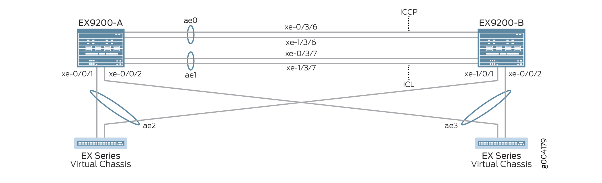
表 2 详细介绍了此配置示例中使用的拓扑。
| 主机名 | 基本硬件 | Multichassis 链路聚合组 |
|---|---|---|
| EX9200-A EX9200-B |
EX9200 EX9200 |
ae0 配置为聚合以太网接口,用作 ICCP 链路,以下接口属于 ae0 的一部分:xe-0/3/6 和 xe-1/3/6。 ae1 配置为聚合以太网接口并用作 ICL 链路,以下接口属于 ae1 的一部分:xe-0/3/7 和 xe-1/3/7。 ae2 配置为 MC-LAG,以下接口属于 ae2: 交换机 B 上的 xe-0/0/1,交换机 A 上的 xe-1/0/1。 ae3 配置为 MC-LAG,交换机 A 和交换机 B 上的 ae3 均包含以下接口: xe-0/0/2。 |
| 虚拟机箱 虚拟机箱 |
不适用。显示虚拟机箱仅用于说明目的。 |
虚拟机箱通过 LAG 接口连接到两台 EX9200 交换机。此示例中不包含虚拟机箱配置,仅用于说明示例拓扑。 |
配置
CLI 快速配置
要快速配置此示例,请复制以下命令,将其粘贴到文本文件中,删除所有换行符,更改详细信息,以便与网络配置匹配,将命令复制并粘贴到层次结构级别的 [edit] CLI 中,然后从配置模式进入。commit
EX9200-A
set system login user MCLAG_Admin uid 2000 set system login user MCLAG_Admin class super-user set system login user MCLAG_Admin authentication encrypted-password "$ABC123" set system static-host-mapping EX9200-A inet 10.92.76.2 set system static-host-mapping EX9200-B inet 10.92.76.4 set system services netconf ssh set system commit peers-synchronize set system commit peers EX9200-B user MCLAG_Admin set system commit peers EX9200-B authentication "$ABC123" set interfaces irb unit 100 family inet address 192.168.100.2/24 arp 192.168.100.3 l2-interface ae1 set interfaces irb unit 100 family inet address 192.168.100.2/24 arp 192.168.100.3 mac 28:8a:1c:e5:3b:f0 set interfaces irb unit 100 family inet address 192.168.100.2/24 vrrp-group 1 virtual-address 192.168.100.1 set interfaces irb unit 100 family inet address 192.168.100.2/24 vrrp-group 1 priority 150 set interfaces irb unit 100 family inet address 192.168.100.2/24 vrrp-group 1 accept-data set interfaces lo0 unit 0 family inet address 172.16.32.5/32 set routing-options static route 0.0.0.0/0 next-hop 10.92.77.254 set protocols ospf area 0.0.0.0 interface lo0.0 passive set protocols ospf area 0.0.0.0 interface ae0.0 set protocols lldp interface all set chassis aggregated-devices ethernet device-count 20 set groups MC_Config_Global set groups MC_Config_Global when peers EX9200-A set groups MC_Config_Global when peers EX9200-B set groups MC_Config_Global interfaces xe-0/3/6 ether-options 802.3ad ae0 set groups MC_Config_Global interfaces xe-1/3/6 ether-options 802.3ad ae0 set groups MC_Config_Global interfaces ae0 description "ICCP Layer 3 Link with 2 members,xe-0/3/6,xe-1/3/6" set groups MC_Config_Global interfaces ae0 aggregated-ether-options lacp active set groups MC_Config_Global interfaces ae0 aggregated-ether-options lacp periodic fast set groups MC_Config_Global interfaces ae0 aggregated-ether-options lacp system-id 00:01:02:03:04:05 set groups MC_Config_Global interfaces ae0 aggregated-ether-options lacp admin-key 0 set groups MC_Config_Global interfaces xe-0/3/7 ether-options 802.3ad ae1 set groups MC_Config_Global interfaces xe-1/3/7 ether-options 802.3ad ae1 set groups MC_Config_Global interfaces ae1 description "ICL Layer 2 link with 2 members,xe-0/3/7,1/3/7" set groups MC_Config_Global interfaces ae1 unit 0 family ethernet-switching interface-mode trunk set groups MC_Config_Global interfaces ae1 unit 0 family ethernet-switching vlan members all set groups MC_Config_Global interfaces ae1 vlan-tagging set groups MC_Config_Global interfaces ae1 aggregated-ether-options lacp active set groups MC_Config_Global interfaces ae1 aggregated-ether-options lacp periodic fast set groups MC_Config_Global interfaces ae1 aggregated-ether-options lacp system-id 00:01:02:03:04:06 set groups MC_Config_Global interfaces ae1 aggregated-ether-options lacp admin-key 1 set groups MC_Config_Global interfaces xe-0/0/1 ether-options 802.3ad ae2 set groups MC_Config_Global interfaces xe-1/0/1 ether-options 802.3ad ae2 set groups MC_Config_Global interfaces ae2 unit 0 description “MC-LAG interface with members xe-0/0/1,xe-1/0/1” set groups MC_Config_Global interfaces ae2 unit 0 family ethernet-switching interface-mode trunk set groups MC_Config_Global interfaces ae2 unit 0 family ethernet-switching vlan members all set groups MC_Config_Global interfaces ae2 aggregated-ether-options lacp active set groups MC_Config_Global interfaces ae2 aggregated-ether-options lacp periodic fast set groups MC_Config_Global interfaces ae2 aggregated-ether-options lacp system-id 00:01:02:03:04:07 set groups MC_Config_Global interfaces ae2 aggregated-ether-options lacp admin-key 2 set groups MC_Config_Global interfaces ae2 aggregated-ether-options mc-ae mc-ae-id 2 set groups MC_Config_Global interfaces ae2 aggregated-ether-options mc-ae redundancy-group 1 set groups MC_Config_Global interfaces ae2 aggregated-ether-options mc-ae mode active-active set groups MC_Config_Global interfaces ae2 aggregated-ether-options mc-ae init-delay-time 520 set groups MC_Config_Global interfaces ae2 aggregated-ether-options mc-ae events iccp-peer-down prefer-status-control-active set groups MC_Config_Global interfaces xe-0/0/2 ether-options 802.3ad ae3 set groups MC_Config_Global interfaces ae3 unit 0 description “MC-LAG interface with members xe-0/0/2 on both switches” set groups MC_Config_Global interfaces ae3 unit 0 family ethernet-switching interface-mode trunk set groups MC_Config_Global interfaces ae3 unit 0 family ethernet-switching vlan members all set groups MC_Config_Global interfaces ae3 aggregated-ether-options lacp active set groups MC_Config_Global interfaces ae3 aggregated-ether-options lacp periodic fast set groups MC_Config_Global interfaces ae3 aggregated-ether-options lacp system-id 00:01:02:03:04:08 set groups MC_Config_Global interfaces ae3 aggregated-ether-options lacp admin-key 3 set groups MC_Config_Global interfaces ae3 aggregated-ether-options mc-ae mc-ae-id 3 set groups MC_Config_Global interfaces ae3 aggregated-ether-options mc-ae redundancy-group 1 set groups MC_Config_Global interfaces ae3 aggregated-ether-options mc-ae mode active-active set groups MC_Config_Global interfaces ae3 aggregated-ether-options mc-ae init-delay-time 520 set groups MC_Config_Global interfaces ae3 aggregated-ether-options mc-ae events iccp-peer-down prefer-status-control-active set groups MC_Config_Global vlans v100 vlan-id 100 set groups MC_Config_Global vlans v100 l3-interface irb.100 set groups MC_Config_Global multi-chassis mc-lag consistency-check set groups MC_Config_Global protocols rstp interface ae2 set groups MC_Config_Global protocols rstp interface ae3 set groups MC_Config_Global protocols rstp bridge-priority 0 set groups MC_Config_Global protocols rstp system-id 00:01:02:03:04:09 set groups MC_Config_Global switch-options service-id 1 set groups MC_Config_Local set groups MC_Config_Local interfaces ae0 unit 0 family inet address 172.16.32.9/30 set groups MC_Config_Local interfaces ae2 aggregated-ether-options mc-ae chassis-id 0 set groups MC_Config_Local interfaces ae2 aggregated-ether-options mc-ae status-control active set groups MC_Config_Local interfaces ae3 aggregated-ether-options mc-ae chassis-id 0 set groups MC_Config_Local interfaces ae3 aggregated-ether-options mc-ae status-control active set groups MC_Config_Remote set groups MC_Config_Remote interfaces ae0 unit 0 family inet address 172.16.32.10/30 set groups MC_Config_Remote interfaces ae2 aggregated-ether-options mc-ae chassis-id 1 set groups MC_Config_Remote interfaces ae2 aggregated-ether-options mc-ae status-control standby set groups MC_Config_Remote interfaces ae3 aggregated-ether-options mc-ae chassis-id 1 set groups MC_Config_Remote interfaces ae3 aggregated-ether-options mc-ae status-control standby set interfaces ae2 unit 0 multi-chassis-protection 172.16.32.6 interface ae1 set interfaces ae3 unit 0 multi-chassis-protection 172.16.32.6 interface ae1 set protocols iccp local-ip-addr 172.16.32.5 set protocols iccp peer 172.16.32.6 session-establishment-hold-time 50 set protocols iccp peer 172.16.32.6 redundancy-group-id-list 1 set protocols iccp peer 172.16.32.6 backup-liveness-detection backup-peer-ip 10.92.76.4 set protocols iccp peer 172.16.32.6 liveness-detection minimum-interval 2000 set protocols iccp peer 172.16.32.6 liveness-detection multiplier 4 set multi-chassis multi-chassis-protection 172.16.32.6 interface ae1 set apply-groups [ MC_Config_Global MC_Config_Local MC_Config_Remote ]
EX9200-B
set system login user MCLAG_Admin uid 2000 set system login user MCLAG_Admin class super-user set system login user MCLAG_Admin authentication encrypted-password "$ABC123" set system static-host-mapping EX9200-A inet 10.92.76.2 set system static-host-mapping EX9200-B inet 10.92.76.4 set system services netconf ssh set system commit peers-synchronize set system commit peers EX9200-A user MCLAG_Admin set system commit peers EX9200-A authentication "$ABC123" set interfaces irb unit 100 family inet address 192.168.100.3/24 arp 192.168.100.2 l2-interface ae1 set interfaces irb unit 100 family inet address 192.168.100.3/24 arp 192.168.100.2 mac 28:8a:1c:e3:f7:f0 set interfaces irb unit 100 family inet address 192.168.100.3/24 vrrp-group 1 virtual-address 192.168.100.1 set interfaces irb unit 100 family inet address 192.168.100.3/24 vrrp-group 1 priority 100 set interfaces irb unit 100 family inet address 192.168.100.3/24 vrrp-group 1 accept-data set interfaces lo0 unit 0 family inet address 172.16.32.6/32 set routing-options static route 0.0.0.0/0 next-hop 10.92.77.254 set protocols ospf area 0.0.0.0 interface lo0 passive set protocols ospf area 0.0.0.0 interface ae0 set protocols lldp interface all set chassis aggregated-devices ethernet device-count 20 set interfaces ae2 unit 0 multi-chassis-protection 172.16.32.5 interface ae1 set interfaces ae3 unit 0 multi-chassis-protection 172.16.32.5 interface ae1 set protocols iccp local-ip-addr 172.16.32.6 set protocols iccp peer 172.16.32.5 session-establishment-hold-time 50 set protocols iccp peer 172.16.32.5 redundancy-group-id-list 1 set protocols iccp peer 172.16.32.5 backup-liveness-detection backup-peer-ip 10.92.76.2 set protocols iccp peer 172.16.32.5 liveness-detection minimum-interval 2000 set protocols iccp peer 172.16.32.5 liveness-detection multiplier 4 set apply-groups [ MC_Config_Global MC_Config_Local MC_Config_Remote ]
在 EX9200-A 上配置 MC-LAG
分步程序
下面的示例要求您在各个配置层级中进行导航。
-
创建用于访问交换机的用户帐户,以及用户标识符 (UID)、登录类和密码。
[edit system] user@EX9200-A# set login user MCLAG_Admin uid 2000 user@EX9200-A# set login user MCLAG_Admin class super-user user@EX9200-A# set login user MCLAG_Admin authentication encrypted-password “$ABC123”
-
将 EX9200-A 静态映射到 10.92.76.2,将 EX9200-B 静态映射到 10.92.76.4。
[edit system] user@EX9200-A# set static-host-mapping EX9200-A inet 10.92.76.2 user@EX9200-A# set static-host-mapping EX9200-B inet 10.92.76.4
-
使用 SSH 启用 NETCONF 服务。
[edit system] user@EX9200-A# set services netconf ssh
-
启用该
peers-synchronize语句以默认将 MC-LAG 配置从 EX9200-A 复制并加载到 EX9200-B。[edit system] user@EX9200-A# set commit peers-synchronize
-
配置 EX9200-B(EX9200-A 将与之同步 MC-LAG 配置的对等方)的主机名、用户名和身份验证详细信息。
[edit system] user@EX9200-A# set commit peers EX9200-B user MCLAG_Admin user@EX9200-A# set commit peers EX9200-B user authentication “$ABC123”
-
在 MC-LAG IRB 对等方上配置 MC-LAG IRB 并配置静态地址解析协议 (ARP),以允许路由协议遍历 IRB 接口。
[edit interfaces] user@EX9200-A# set irb unit 100 family inet address 192.168.100.2/24 arp 192.168.100.3 l2-interface ae1 user@EX9200-A# set irb unit 100 family inet address 192.168.100.2/24 arp 192.168.100.3 mac 28:8a:1c:e5:3b:f0
-
通过分配在 VRRP 组中的每台交换机之间共享的虚拟 IP 地址,并为 VRRP 组中的每个成员分配单独的 IP 地址,在 MC-LAG 上启用 VRRP。
[edit interfaces] user@EX9200-A# set irb unit 100 family inet address 192.168.100.2/24 vrrp-group 1 virtual-address 192.168.100.1 user@EX9200-A# set irb unit 100 family inet address 192.168.100.2/24 vrrp-group 1 priority 150 user@EX9200-A# set irb unit 100 family inet address 192.168.100.2/24 vrrp-group 1 accept-data
-
配置环路接口。
[edit interfaces] user@EX9200-A# set lo0 unit 0 family inet address 172.16.32.5/32
-
配置默认网关。
[edit routing-options] user@EX9200-A# set static route 0.0.0.0 next-hop 10.92.77.254
-
配置一个包括环路接口和 ICCP 接口的 OSPF 区域。
[edit protocols] user@EX9200-A# set ospf area 0.0.0.0 interface lo0 passive user@EX9200-A# set ospf area 0.0.0.0 interface ae0
-
为所有接口配置链路层发现协议。
[edit protocols] user@EX9200-A# set lldp interface all
-
配置要在 EX9200-A 上创建的聚合以太网接口数量。
[edit chassis] user@EX9200-A# set aggregated-devices ethernet device-count 20
-
为适用于 EX9200-A 和 EX9200-B 的全局 MC-LAG 配置配置一个配置组。
全局配置在 EX9200-A 和 EX9200-B 之间同步。
[edit groups] user@EX9200-A# set MC_Config_Global
-
指定将应用 MC_Config_Global 配置组的对等方。
[edit groups] user@EX9200-A# set MC_Config_Global when peers EX9200-A user@EX9200-A# set MC_Config_Global when peers EX9200-B
-
将成员接口添加到将用于机箱间控制协议 (ICCP) 接口的聚合以太网接口。
[edit groups] user@EX9200-A# set MC_Config_Global interfaces xe-0/3/6 ether-options 802.3ad ae0 user@EX9200-A# set MC_Config_Global interfaces xe-1/3/6 ether-options 802.3ad ae0
-
配置将用于机箱间控制协议 (ICCP) 接口的聚合以太网接口 (ae0)。
注意:您将在后面的步骤中配置 ae0 的 IP 地址。
[edit groups] user@EX9200-A# set MC_Config_Global interfaces ae0 description "ICCP Layer 3 Link with 2 members,xe-0/3/6,xe-1/3/6"
-
在 ae0 上配置 LACP 参数。
[edit groups] user@EX9200-A# set MC_Config_Global interfaces ae0 aggregated-ether-options lacp active user@EX9200-A# set MC_Config_Global interfaces ae0 aggregated-ether-options lacp periodic fast
-
在 ae0 上配置 LACP 系统 ID。
[edit groups] user@EX9200-A# set MC_Config_Global interfaces ae0 aggregated-ether-options lacp system-id 00:01:02:03:04:05
-
在 ae0 上配置 LACP 管理密钥。
[edit groups] user@EX9200-A# set MC_Config_Global interfaces ae0 aggregated-ether-options lacp admin-key 0
-
将成员接口添加到将用于 ICL 的聚合以太网接口 (ae1)。
[edit groups] user@EX9200-A# set MC_Config_Global interfaces xe-0/3/7 ether-options 802.3ad ae1 user@EX9200-A# set MC_Config_Global interfaces xe-1/3/7 ether-options 802.3ad ae1
-
配置将用于 ICL 的聚合以太网接口。
[edit groups] user@EX9200-A# set MC_Config_Global interfaces ae1 description "ICL Layer 2 link with 2 members,xe-0/3/7,1/3/7"
-
将 ae1 配置为第 2 层接口。
[edit groups] user@EX9200-A# set MC_Config_Global ae1 unit 0 family ethernet-switching interface-mode trunk user@EX9200-A# set MC_Config_Global ae1 unit 0 family ethernet-switching vlan members all
-
在 ae1 上启用接收和传输带有 802.1Q VLAN 标记的帧。
[edit groups] user@EX9200-A# set MC_Config_Global interfaces ae1 vlan-tagging
-
在 ae1 上配置 LACP 参数。
[edit groups] user@EX9200-A# set MC_Config_Global interfaces ae1 aggregated-ether-options lacp active user@EX9200-A# set MC_Config_Global interfaces ae1 aggregated-ether-options lacp periodic fast
-
在 ae1 上配置 LACP 系统 ID。
[edit groups] user@EX9200-A# set MC_Config_Global interfaces ae1 aggregated-ether-options lacp system-id 00:01:02:03:04:06
-
在 ae1 上配置 LACP 管理密钥。
[edit groups] user@EX9200-A# set MC_Config_Global interfaces ae1 aggregated-ether-options lacp admin-key 1
-
将成员接口添加到将用作 MC-LAG 接口的聚合以太网接口 (ae2)。
[edit groups] user@EX9200-A# set MC_Config_Global interfaces xe-0/0/1 ether-options 802.3ad ae2 user@EX9200-A# set MC_Config_Global interfaces xe-1/0/1 ether-options 802.3ad ae2
-
配置将用作 MC-LAG 接口的聚合以太网接口 (ae2)。
[edit groups] user@EX9200-A# set MC_Config_Global interfaces ae2 description “MC-LAG interface with members xe-0/0/1,xe-1/0/1”
-
将 ae2 配置为第 2 层接口。
[edit groups] user@EX9200-A# set MC_Config_Global interfaces ae2 unit 0 family ethernet-switching interface-mode trunk user@EX9200-A# set MC_Config_Global interfaces ae2 unit 0 family ethernet-switching vlan members all
-
在 ae2 上配置 LACP 参数。
[edit groups] user@EX9200-A# set MC_Config_Global interfaces ae2 aggregated-ether-options lacp active user@EX9200-A# set MC_Config_Global interfaces ae2 aggregated-ether-options lacp periodic fast
-
在 ae2 上配置 LACP 系统 ID。
[edit groups] user@EX9200-A# set MC_Config_Global interfaces ae2 aggregated-ether-options lacp system-id 00:01:02:03:04:07
-
在 ae2 上配置 LACP 管理密钥。
[edit groups] user@EX9200-A# set MC_Config_Global interfaces ae2 aggregated-ether-options lacp admin-key 2
-
在 ae2 上配置 MC-AE 接口属性。
[edit groups] user@EX9200-A# set MC_Config_Global interfaces ae2 aggregated-ether-options mc-ae mc-ae-id 2 user@EX9200-A# set MC_Config_Global interfaces ae2 aggregated-ether-options mc-ae redundancy-group 1
-
指定 ae2 的模式为主动-主动。
[edit groups] user@EX9200-A# set MC_Config_Global interfaces ae2 aggregated-ether-options mc-ae mode active-active
-
指定在重新启动 MC-LAG 对等方后延迟将 MC-AE 接口置于启动状态的时间(以秒为单位)。
通过将接口的启动延迟到协议融合之后,可以防止在恢复故障链路和设备期间发生数据包丢失。此网络配置示例使用的延迟时间为 520 秒。此延迟时间可能不适合您的网络,应根据您的网络要求进行调整。
[edit groups] user@EX9200-A# set MC_Config_Global interfaces ae2 aggregated-ether-options mc-ae init-delay-time 520
-
指定如果 MC-LAG 组的对等方关闭,则配置为状态控制活动的对等方将成为活动对等方。
[edit groups] user@EX9200-A# set MC_Config_Global interfaces ae2 aggregated-ether-options mc-ae events iccp-peer-down prefer-status-control-active
-
将成员接口添加到将用作 MC-LAG 接口的聚合以太网接口 (ae3)。
注意:EX9200-B 使用相同的接口名称 xe-0/0/2。
[edit groups] user@EX9200-A# set MC_Config_Global interfaces xe-0/0/2 ether-options 802.3ad ae3
-
配置将用作 MC-LAG 接口的聚合以太网接口 (ae3)。
[edit groups] user@EX9200-A# set groups MC_Config_Global interfaces ae3 description “MC-LAG interface with members xe-0/0/2 on both switches”
-
将 ae3 配置为第 2 层接口。
[edit groups] user@EX9200-A# set MC_Config_Global interfaces ae3 unit 0 family ethernet-switching interface-mode trunk user@EX9200-A# set MC_Config_Global interfaces ae3 unit 0 family ethernet-switching vlan members all
-
在 ae3 上配置 LACP 参数。
[edit groups] user@EX9200-A# set MC_Config_Global interfaces ae3 aggregated-ether-options lacp active user@EX9200-A# set MC_Config_Global interfaces ae3 aggregated-ether-options lacp periodic fast
-
在 ae3 上配置 LACP 系统 ID。
[edit groups] user@EX9200-A# set MC_Config_Global interfaces ae3 aggregated-ether-options lacp system-id 00:01:02:03:04:08
-
在 ae3 上配置 LACP 管理密钥。
[edit groups] user@EX9200-A# set MC_Config_Global interfaces ae3 aggregated-ether-options lacp admin-key 3
-
在 ae3 上配置 MC-AE 接口属性。
[edit groups] user@EX9200-A# set MC_Config_Global interfaces ae3 aggregated-ether-options mc-ae mc-ae-id 3 user@EX9200-A# set MC_Config_Global interfaces ae3 aggregated-ether-options mc-ae redundancy-group 1
-
指定 ae3 的模式为主动-主动。
[edit groups] user@EX9200-A# set MC_Config_Global interfaces ae3 aggregated-ether-options mc-ae mode active-active
-
指定在重新启动 MC-LAG 对等方后延迟将 MC-AE 接口置于启动状态的时间(以秒为单位)。
通过将接口的启动延迟到协议融合之后,可以防止在恢复故障链路和设备期间发生数据包丢失。此网络配置示例使用的延迟时间为 520 秒。此延迟时间可能不适合您的网络,应根据您的网络要求进行调整。
[edit groups] user@EX9200-A# set MC_Config_Global interfaces ae3 aggregated-ether-options mc-ae init-delay-time 520
-
指定如果 MC-LAG 组的对等方关闭,则配置为状态控制活动的对等方将成为活动对等方。
[edit groups] user@EX9200-A# set MC_Config_Global interfaces ae3 aggregated-ether-options mc-ae events iccp-peer-down prefer-status-control-active
-
配置 VLAN 100 以连接最终用户。
[edit groups] user@EX9200-A# set MC_Config_Global vlans v100 vlan-id 100
-
为 VLAN 100 配置路由 VLAN 接口。
[edit groups] user@EX9200-A# set MC_Config_Global vlans v100 l3-interface irb.100
-
启用一致性检查。
[edit groups] user@EX9200-A# set MC_Config_Global multi-chassis mc-lag consistency-check
-
在 ae2 和 ae3 接口(MC-LAG 接口)上启用快速生成树协议,以实现可选的环路预防。
[edit groups] user@EX9200-A# set MC_Config_Global protocols rstp interfaces ae2 user@EX9200-A# set MC_Config_Global protocols rstp interfaces ae3
-
配置 RSTP 网桥优先级。
将网桥优先级设置为 0 将使 EX9200-A 和 EX9200-B 的 MC-AE 节点成为最佳优先级。
[edit groups] user@EX9200-A# set MC_Config_Global protocols rstp bridge-priority 0
-
配置 RSTP 系统标识符值。
[edit groups] user@EX9200-A# set MC_Config_Global protocols rstp system-id 00:01:02:03:04:09
-
指定交换机服务 ID。
交换机服务 ID 用于跨 MC-LAG 成员同步应用、ARP 和 MAC 学习。
[edit groups] user@EX9200-A# set MC_Config_Global switch-options service-id 1
-
为适用于本地对等方的 MC-LAG 配置配置配置组。
[edit groups] user@EX9200-A# set MC_Config_Local
-
将 ICCP 接口 (ae0) 配置为第 3 层接口。
[edit groups] user@EX9200-A# set MC_Config_Local interfaces ae0 unit 0 family inet address 172.16.32.9/30
-
为聚合以太网接口所属的 MC-LAG (ae2) 指定唯一的机箱 ID。
[edit groups] user@EX9200-A# set MC_Config_Local interfaces ae2 aggregated-ether-options mc-ae chassis-id 0
-
指定要激活的 ae2 的状态控制设置。
[edit groups] user@EX9200-A# set MC_Config_Local interfaces ae2 aggregated-ether-options mc-ae status-control active
-
为聚合以太网接口所属的 MC-LAG (ae3) 指定唯一的机箱 ID。
[edit groups] user@EX9200-A# set MC_Config_Local interfaces ae3 aggregated-ether-options mc-ae chassis-id 0
-
指定要激活的 ae3 的状态控制设置。
[edit groups] user@EX9200-A# set MC_Config_Local interfaces ae3 aggregated-ether-options mc-ae status-control active
-
为应用于远程对等方的 MC-LAG 配置配置配置组。
[edit groups] user@EX9200-A# set MC_Config_Remote
-
将 ae0 配置为第 3 层接口。
[edit groups] user@EX9200-A# set MC_Config_Remote interfaces ae0 unit 0 family inet address 172.16.32.10/30
-
为聚合以太网接口所属的 MC-LAG (ae2) 指定唯一的机箱 ID。
[edit groups] user@EX9200-A# set MC_Config_Remote interfaces ae2 aggregated-ether-options mc-ae chassis-id 1
-
指定 ae2 待机的状态控制设置。
[edit groups] user@EX9200-A# set MC_Config_Remote interfaces ae2 aggregated-ether-options mc-ae status-control standby
-
为聚合以太网接口所属的 MC-LAG (ae3) 指定唯一的机箱 ID。
[edit groups] user@EX9200-A# set MC_Config_Remote interfaces ae3 aggregated-ether-options mc-ae chassis-id 1
-
指定要备用的 ae3 的状态控制设置。
[edit interfaces] user@EX9200-A# set MC_Config_Remote interfaces ae3 aggregated-ether-options mc-ae status-control standby
-
指定如果 MC-LAG 组的对等方关闭,则配置为状态控制活动的对等方将成为活动对等方。
[edit interfaces] user@EX9200-A# set MC_Config_Remote interfaces ae3 aggregated-ether-options mc-ae events iccp-peer-down prefer-status-control-standby
-
在两个 MC-LAG 对等方之间启用链路保护。
将接口 ae1 分配为 ICL,以便在发生故障时保护 MC-AE 接口 ae2 和 ae3。
[edit interfaces] user@EX9200-A# set ae2 unit 0 multi-chassis-protection 172.16.32.6 interface ae1
user@EX9200-A# set ae3 unit 0 multi-chassis-protection 172.16.32.6 interface ae1
-
指定 ICCP 接口的本地 IP 地址。
[edit protocols] user@EX9200-A# set iccp local-ip-addr 172.16.32.5
-
配置会话建立保持时间,以便 ICCP 能够更快地连接。
注意:建议将 50 秒作为会话建立保持时间值。
[edit protocols] user@EX9200-A# set iccp peer 172.16.32.6 session-establishment-hold-time 50 user@EX9200-A# set iccp peer 172.16.32.6 redundancy-group-id-list 1 user@EX9200-A# set iccp peer 172.16.32.6 backup-liveness-detection backup-peer-ip 10.92.76.4
-
要为 ICCP 启用 BFD,请配置最小接收间隔。
建议最小接收间隔值为 6 秒。
[edit protocols] user@EX9200-A# set iccp peer 172.16.32.6 liveness-detection minimum-interval 2000 user@EX9200-A# set iccp peer 172.16.32.6 liveness-detection multiplier 4
-
应用之前配置的组,以便 Junos 配置继承 MC_Config_Global、MC_Config_Local 和 MC_Config_Remote 配置组的语句。
[edit] user@EX9200-A# set apply-groups [ MC_Config_Global MC_Config_Local MC_Config_Remote ]
在 EX9200-B 上配置 MC-LAG
分步程序
下面的示例要求您在各个配置层级中进行导航。
-
创建用于访问交换机的用户帐户,以及用户标识符 (UID)、登录类和密码。
[edit system] user@EX9200-A# set login user MCLAG_Admin uid 2000 user@EX9200-B# set login user MCLAG_Admin class super-user user@EX9200-B# set login user MCLAG_Admin authentication encrypted-password “$ABC123”
-
将 EX9200-A 静态映射到 10.92.76.2,将 EX9200-B 静态映射到 10.92.76.4。
[edit system] user@EX9200-B# set static-host-mapping EX9200-A inet 10.92.76.2 user@EX9200-B# set static-host-mapping EX9200-B inet 10.92.76.4
-
使用 SSH 启用 NETCONF 服务。
[edit system] user@EX9200-B# set services netconf ssh
-
启用该
peers-synchronize语句以默认情况下将 MC-LAG 配置从 EX9200-B 复制并加载到 EX9200-A。[edit system] user@EX9200-B# set commit peers-synchronize
-
为 EX9200-A(EX9200-B 将与之同步 MC-LAG 配置的对等方)配置主机名、用户名和身份验证详细信息。
[edit system] user@EX9200-B# set commit peers EX9200-A user MCLAG_Admin user@EX9200-A# set commit peers EX9200-A authentication "$ABC123"
-
在 MC-LAG IRB 对等方上配置 MC-LAG IRB 并配置静态地址解析协议 (ARP),以允许路由协议遍历 IRB 接口。
[edit interfaces] user@EX9200-B# set irb unit 100 family inet address 192.168.100.3/24 arp 192.168.100.2 l2-interface ae1 user@EX9200-B# set irb unit 100 family inet address 192.168.100.3/24 arp 192.168.100.2 mac 28:8a:1c:e3:f7:f0
-
通过分配在 VRRP 组中的每台交换机之间共享的虚拟 IP 地址,并为 VRRP 组中的每个成员分配单独的 IP 地址,在 MC-LAG 上启用 VRRP。
[edit interfaces] user@EX9200-B# set irb unit 100 family inet address 192.168.100.3/24 vrrp-group 1 virtual-address 192.168.100.1 user@EX9200-B# set irb unit 100 family inet address 192.168.100.3/24 vrrp-group 1 priority 100 user@EX9200-B# set irb unit 100 family inet address 192.168.100.3/24 vrrp-group 1 accept-data
-
配置环路接口。
[edit interfaces] user@EX9200-B# set lo0 unit 0 family inet address 172.16.32.6/32
-
配置默认网关。
[edit routing-options] user@EX9200-B# set static route 0.0.0.0 next-hop 10.92.77.254
-
配置一个包括环路接口和 ICCP 接口的 OSPF 区域。
[edit protocols] user@EX9200-B# set ospf area 0.0.0.0 interface lo0 passive user@EX9200-B# set ospf area 0.0.0.0 interface ae0
-
为所有接口配置链路层发现协议。
[edit protocols] user@EX9200-B# set lldp interface all
-
配置要在 EX9200-B 上创建的聚合以太网接口数量。
[edit chassis] user@EX9200-B# set aggregated-devices ethernet device-count 20
-
在两个 MC-LAG 对等方之间启用链路保护。
将接口 ae1 分配为 ICL,以便在发生故障时保护 MC-AE 接口 ae2 和 ae3。
[edit interfaces] user@EX9200-B# set ae2 unit 0 multi-chassis-protection 172.16.32.5 interface ae1 user@EX9200-B# set ae3 unit 0 multi-chassis-protection 172.16.32.5 interface ae1
-
指定 ICCP 接口的本地 IP 地址。
[edit protocols] user@EX9200-B# set iccp local-ip-addr 172.16.32.6
-
配置会话建立保持时间,以便 ICCP 能够更快地连接。
注意:建议将 50 秒作为会话建立保持时间值。
[edit protocols] user@EX9200-B# set iccp peer 172.16.32.5 session-establishment-hold-time 50 user@EX9200-B# set iccp peer 172.16.32.5 redundancy-group-id-list 1 user@EX9200-B# set iccp peer 172.16.32.5 backup-liveness-detection backup-peer-ip 10.92.76.2
-
要为 ICCP 启用 BFD,请配置最小接收间隔。
建议最小接收间隔值为 6 秒。
[edit protocols] user@EX9200-B# set iccp peer 172.16.32.5 liveness-detection minimum-interval 2000 user@EX9200-B# set iccp peer 172.16.32.5 liveness-detection multiplier 4
-
应用之前配置的组,以便 Junos 配置继承 MC_Config_Global、MC_Config_Local 和 MC_Config_Remote 配置组的语句。
[edit] user@EX9200-B# set apply-groups [ MC_Config_Global MC_Config_Local MC_Config_Remote ]
结果
在提交配置之前,在 EX9200-A 上显示配置结果。
user@EX9200-A# show system services
netconf {
ssh;
}
user@EX9200-A# show system commit
peers-synchronize;
peers {
EX9200-B {
user MCLAG_Admin;
authentication "$ABC123”;
}
}
}
user@EX9200-A# show interfaces
ae2 {
unit 0 {
multi-chassis-protection 172.16.32.6 {
interface ae1;
}
}
}
ae3 {
unit 0 {
multi-chassis-protection 172.16.32.6 {
interface ae1;
}
}
}
irb {
unit 100 {
family inet {
address 192.168.100.2/24 {
arp 192.168.100.3 l2-interface ae1.0 mac 28:8a:1c:e5:3b:f0;
vrrp-group 1 {
virtual-address 192.168.100.1;
priority 150;
accept-data;
}
}
}
}
}
lo0 {
unit 0 {
family inet {
address 172.16.32.5/32;
}
}
}
user@EX9200-A# show routing-options
static {
route 0.0.0.0/0 next-hop 10.92.77.254;
}
user@EX9200-A# show protocols
ospf {
area 0.0.0.0 {
interface lo0.0 {
passive;
}
interface ae0.0;
}
}
iccp {
local-ip-addr 172.16.32.5;
peer 172.16.32.6 {
session-establishment-hold-time 50;
redundancy-group-id-list 1;
backup-liveness-detection {
backup-peer-ip 10.92.76.4;
}
liveness-detection {
minimum-interval 2000;
multiplier 4;
}
}
}
lldp {
interface all;
}
user@EX9200-A# show chassis
aggregated-devices {
ethernet {
device-count 20;
}
}
user@EX9200-A# show groups MC_Config_Global
when {
peers [ EX9200-A EX9200-B ];
}
interfaces {
xe-0/3/6 {
ether-options {
802.3ad ae0;
}
}
xe-1/3/6 {
ether-options {
802.3ad ae0;
}
}
ae0 {
description "ICCP Layer 3 Link with 2 members,xe-0/3/6,xe-1/3/6";
aggregated-ether-options {
lacp {
active;
periodic fast;
system-id 00:01:02:03:04:05;
admin-key 0;
}
}
}
xe-0/3/7 {
ether-options {
802.3ad ae1;
}
}
xe-1/3/7 {
ether-options {
802.3ad ae1;
}
}
ae1 {
description "ICL Layer 2 link with 2 members,xe-0/3/7,1/3/7";
vlan-tagging;
aggregated-ether-options {
lacp {
active;
periodic fast;
system-id 00:01:02:03:04:06;
admin-key 1;
}
}
unit 0 {
family ethernet-switching {
interface-mode trunk;
vlan {
members all;
}
}
}
}
xe-0/0/1 {
ether-options {
802.3ad ae2;
}
}
xe-1/0/1 {
ether-options {
802.3ad ae2;
}
}
ae2 {
description "MC-LAG interface with members xe-0/0/1,xe-1/0/1";
aggregated-ether-options {
lacp {
active;
periodic fast;
system-id 00:01:02:03:04:07;
admin-key 2;
}
mc-ae {
mc-ae-id 2;
redundancy-group 1;
mode active-active;
init-delay-time 520;
events {
iccp-peer-down {
prefer-status-control-active;
}
}
}
}
unit 0 {
family ethernet-switching {
interface-mode trunk;
vlan {
members all;
}
}
}
}
xe-0/0/2 {
ether-options {
802.3ad ae3;
}
}
ae3 {
description “MC-LAG interface with members xe-0/0/2 on both switches”
aggregated-ether-options {
lacp {
active;
periodic fast;
system-id 00:01:02:03:04:08;
admin-key 3;
}
mc-ae {
mc-ae-id 3;
redundancy-group 1;
mode active-active;
init-delay-time 520;
events {
iccp-peer-down {
prefer-status-control-active;
}
}
}
}
unit 0 {
family ethernet-switching {
interface-mode trunk;
vlan {
members all;
}
}
}
}
}
multi-chassis {
mc-lag {
consistency-check;
}
}
protocols {
rstp {
bridge-priority 0;
system-id 00:01:02:03:04:09;
interface ae2;
interface ae3;
}
}
switch-options {
service-id 1;
}
vlans {
v100 {
vlan-id 100;
l3-interface irb.100;
}
}
user@EX9200-A# show groups MC_Config_Local
interfaces {
ae0 {
unit 0 {
family inet {
address 172.16.32.9/30;
}
}
}
ae2 {
aggregated-ether-options {
mc-ae {
chassis-id 0;
status-control active;
}
}
}
ae3 {
aggregated-ether-options {
mc-ae {
chassis-id 0;
status-control active;
}
}
}
}
user@EX9200-A# show groups MC_Config_Remote
interfaces {
ae0 {
unit 0 {
family inet {
address 172.16.32.10/30;
}
}
}
ae2 {
aggregated-ether-options {
mc-ae {
chassis-id 1;
status-control standby;
}
}
}
ae3 {
aggregated-ether-options {
mc-ae {
chassis-id 1;
status-control standby;
}
}
}
}
user@EX9200-A# show apply-groups apply-groups [ MC_Config_Global MC_Config_Local MC_Config_Remote ];
在提交配置之前,在 EX9200-B 上显示配置结果。
user@EX9200-B# show system services
netconf {
ssh;
}
user@EX9200-B# show system commit
peers-synchronize;
peers {
EX9200-A {
user MCLAG_Admin;
authentication "$ABC123”;
}
}
user@EX9200-B# show interfaces
ae2 {
unit 0 {
multi-chassis-protection 172.16.32.5 {
interface ae1;
}
}
}
ae3 {
unit 0 {
multi-chassis-protection 172.16.32.5 {
interface ae1;
}
}
}
irb {
unit 100 {
family inet {
address 192.168.100.3/24 {
arp 192.168.100.2 l2-interface ae1.0 mac 28:8a:1c:e3:f7:f0;
vrrp-group 1 {
virtual-address 192.168.100.1;
priority 100;
accept-data;
}
}
}
}
}
lo0 {
unit 0 {
family inet {
address 172.16.32.6/32;
}
}
}
user@EX9200-B# show routing-options
static {
route 0.0.0.0/0 next-hop 10.92.77.254;
}
user@EX9200-B# show protocols
ospf {
area 0.0.0.0 {
interface lo0.0 {
passive;
}
interface ae0.0;
}
}
iccp {
local-ip-addr 172.16.32.6;
peer 172.16.32.5 {
session-establishment-hold-time 50;
redundancy-group-id-list 1;
backup-liveness-detection {
backup-peer-ip 10.92.76.2;
}
liveness-detection {
minimum-interval 2000;
multiplier 4;
}
}
}
lldp {
interface all;
}
user@EX9200-B# show chassis
aggregated-devices {
ethernet {
device-count 20;
}
}
user@EX9200-B# show apply-groups [ MC_Config_Global MC_Config_Local MC_Config_Remote ];
验证
- 验证 MC-LAG 上的 ICCP
- 验证 MC-LAG 上的 LACP
- 验证 MC-LAG 中的聚合以太网接口
- 验证 MC-LAG 上的 MAC 学习
- 验证 MC-LAG 中的 VRRP
- 验证 MC-LAG 上的 OSPF
- 验证配置一致性检查是否通过
- 验证全局配置的配置一致性检查状态
- 验证机箱间控制链路的配置一致性检查状态
- 验证 MC-LAG 接口的配置一致性检查状态
- 验证 VLAN 配置的配置一致性检查状态
- 验证 VRRP 的配置一致性检查状态
验证 MC-LAG 上的 ICCP
目的
验证 ICCP 是否在 MC-LAG 中的每台设备上运行。
行动
-
验证 ICCP 是否在 EX9200-A 上运行。
user@EX92000-A> show iccp Redundancy Group Information for peer 172.16.32.6 TCP Connection : Established Liveliness Detection : Up Backup liveness peer status: Up Redundancy Group ID Status 1 Up Client Application: lacpd Redundancy Group IDs Joined: 1 Client Application: l2ald_iccpd_client Redundancy Group IDs Joined: 1 Client Application: mclag_cfgchkd Redundancy Group IDs Joined: 1 -
验证 ICCP 是否在 EX9200-B 上运行。
user@EX9200-B> show iccp Redundancy Group Information for peer 172.16.32.5 TCP Connection : Established Liveliness Detection : Up Backup liveness peer status: Up Redundancy Group ID Status 1 Up Client Application: lacpd Redundancy Group IDs Joined: 1 Client Application: l2ald_iccpd_client Redundancy Group IDs Joined: 1 Client Application: mclag_cfgchkd Redundancy Group IDs Joined: 1
意义
此输出显示,托管 MC-LAG 的对等方之间的 TCP 连接已开启,活性检测已启动,备份活性对等方状态已启动,并且 LACPD、MCLAG_CFGCHKD 和 L2ALD _ICCP_CLIENT客户端应用程序正在运行。
验证 MC-LAG 上的 LACP
目的
验证 LACP 是否在 MC-LAG 中的每台设备上正常工作。
行动
-
验证 LACP 接口是否在 EX9200-A 上启动并运行。
user@EX9200-A> show lacp interfaces Aggregated interface: ae0 LACP state: Role Exp Def Dist Col Syn Aggr Timeout Activity xe-0/3/6 Actor No No Yes Yes Yes Yes Fast Active xe-0/3/6 Partner No No Yes Yes Yes Yes Fast Active xe-1/3/6 Actor No No Yes Yes Yes Yes Fast Active xe-1/3/6 Partner No No Yes Yes Yes Yes Fast Active LACP protocol: Receive State Transmit State Mux State xe-0/3/6 Current Fast periodic Collecting distributing xe-1/3/6 Current Fast periodic Collecting distributing Aggregated interface: ae1 LACP state: Role Exp Def Dist Col Syn Aggr Timeout Activity xe-0/3/7 Actor No No Yes Yes Yes Yes Fast Active xe-0/3/7 Partner No No Yes Yes Yes Yes Fast Active xe-1/3/7 Actor No No Yes Yes Yes Yes Fast Active xe-1/3/7 Partner No No Yes Yes Yes Yes Fast Active LACP protocol: Receive State Transmit State Mux State xe-0/3/7 Current Fast periodic Collecting distributing xe-1/3/7 Current Fast periodic Collecting distributing Aggregated interface: ae2 LACP state: Role Exp Def Dist Col Syn Aggr Timeout Activity xe-0/0/1 Actor No Yes No No No Yes Fast Active xe-0/0/1 Partner No Yes No No No Yes Fast Passive LACP protocol: Receive State Transmit State Mux State xe-0/0/1 Current Fast periodic Collecting distributing xe-1/0/1 Port disabled Fast periodic Collecting distributing Aggregated interface: ae3 LACP state: Role Exp Def Dist Col Syn Aggr Timeout Activity xe-0/0/2 Actor No Yes No No No Yes Fast Active xe-0/0/2 Partner No Yes No No No Yes Fast Passive LACP protocol: Receive State Transmit State Mux State xe-0/0/2 Current Fast periodic Collecting distributing -
验证 LACP 接口是否在 EX9200-B 上启动并运行。
user@EX9200-B> show lacp interfaces Aggregated interface: ae0 LACP state: Role Exp Def Dist Col Syn Aggr Timeout Activity xe-0/3/6 Actor No No Yes Yes Yes Yes Fast Active xe-0/3/6 Partner No No Yes Yes Yes Yes Fast Active xe-1/3/6 Actor No No Yes Yes Yes Yes Fast Active xe-1/3/6 Partner No No Yes Yes Yes Yes Fast Active LACP protocol: Receive State Transmit State Mux State xe-0/3/6 Current Fast periodic Collecting distributing xe-1/3/6 Current Fast periodic Collecting distributing Aggregated interface: ae1 LACP state: Role Exp Def Dist Col Syn Aggr Timeout Activity xe-0/3/7 Actor No No Yes Yes Yes Yes Fast Active xe-0/3/7 Partner No No Yes Yes Yes Yes Fast Active xe-1/3/7 Actor No No Yes Yes Yes Yes Fast Active xe-1/3/7 Partner No No Yes Yes Yes Yes Fast Active LACP protocol: Receive State Transmit State Mux State xe-0/3/7 Current Fast periodic Collecting distributing xe-1/3/7 Current Fast periodic Collecting distributing Aggregated interface: ae2 LACP state: Role Exp Def Dist Col Syn Aggr Timeout Activity xe-1/0/1 Actor No Yes No No No Yes Fast Active xe-1/0/1 Partner No Yes No No No Yes Fast Passive LACP protocol: Receive State Transmit State Mux State xe-0/0/1 Current Fast periodic Collecting distributing xe-1/0/1 Current Fast periodic Collecting distributing Aggregated interface: ae3 LACP state: Role Exp Def Dist Col Syn Aggr Timeout Activity xe-0/0/2 Actor No Yes No No No Yes Fast Active xe-0/0/2 Partner No Yes No No No Yes Fast Passive LACP protocol: Receive State Transmit State Mux State xe-0/0/2 Current Fast periodic Collecting distributing
意义
此输出意味着设备和所有相关接口都正确参与 LACP 协商。
验证 MC-LAG 中的聚合以太网接口
目的
验证是否在 MC–LAG 中正确配置了所有 ae 接口。
行动
-
验证 EX9200-A 上的 ae 接口。
user@EX9200-A> show interfaces mc-ae Member Link : ae2 Current State Machine's State: mcae active state Configuration Error Status : No Error Local Status : active Local State : up Peer Status : active Peer State : up Logical Interface : ae2.0 Topology Type : bridge Local State : up Peer State : up Peer Ip/MCP/State : 172.16.32.6 ae1.0 up Member Link : ae3 Current State Machine's State: mcae active state Configuration Error Status : No Error Local Status : active Local State : up Peer Status : active Peer State : up Logical Interface : ae3.0 Topology Type : bridge Local State : up Peer State : up Peer Ip/MCP/State : 172.16.32.6 ae1.0 up -
验证 EX9200-B 上的 ae 接口。
user@EX9200-B> show interface mc-ae Member Link : ae2 Current State Machine's State: mcae active state Configuration Error Status : No Error Local Status : active Local State : up Peer Status : active Peer State : up Logical Interface : ae2.0 Topology Type : bridge Local State : up Peer State : up Peer Ip/MCP/State : 172.16.32.5 ae1.0 up Member Link : ae3 Current State Machine's State: mcae active state Configuration Error Status : No Error Local Status : active Local State : down Peer Status : active Peer State : down Logical Interface : ae3.0 Topology Type : bridge Local State : up Peer State : up Peer Ip/MCP/State : 172.16.32.5 ae1.0 up
意义
此输出表示每个设备上的 mc-ae 接口均已启动且处于活动状态。
验证 MC-LAG 上的 MAC 学习
目的
验证设备之间的 MAC 学习是否在 MC-LAG 中发生。
行动
-
显示 EX9200-A 上的以太网交换表。
user@EX9200-A> show ethernet-switching table MAC flags (S - static MAC, D - dynamic MAC, L - locally learned, P - Persistent static, C - Control MAC SE - statistics enabled, NM - non configured MAC, R - remote PE MAC, O - ovsdb MAC) Ethernet switching table : 2 entries, 2 learned Routing instance : EVPN-2 Vlan MAC MAC Age Logical NH RTR name address flags interface Index ID v100 10:0e:7e:b1:01:80 DC - pip-7.040010000000 1048580 1048580 v100 4c:96:14:e7:fd:81 DRC - ae10.200 0 0 -
显示 EX9200-B 上的以太网交换表。
user@EX9200-B> show ethernet-switching table MAC flags (S - static MAC, D - dynamic MAC, L - locally learned, P - Persistent static, C - Control MAC SE - statistics enabled, NM - non configured MAC, R - remote PE MAC, O - ovsdb MAC) Ethernet switching table : 2 entries, 2 learned Routing instance : EVPN-2 Vlan name MAC address MAC flags Age Logical interface NH Index RTR ID v100 10:0e:7e:b1:01:80 DC - pip-7.060010000000 1048581 1048580 v100 4c:96:14:e7:fd:81 D - ae10.200 0 0
意义
此输出意味着可以在 MC-LAG 中定义的共享 VLAN 中正确学习 MAC 地址。
验证 MC-LAG 中的 VRRP
目的
验证 MC-LAG 中的设备之间的 VRRP 是否已启动且处于活动状态。
行动
-
确认 EX9200-A 上的 VRRP 已启动并处于活动状态。
user@EX9200-A> show vrrp Interface State Group VR state VR Mode Timer Type Address irb.100 up 1 master Active A 0.789 lcl 192.168.100.2 vip 192.168.100.1在此示例中,交换机 A 是主 VRRP 成员。
-
确认 EX9200-B 上的 VRRP 已启动且处于活动状态。
user@EX9200-B> show vrrp Interface State Group VR state VR Mode Timer Type Address irb.100 up 1 backup Active D 2.887 lcl 192.168.100.3 vip 192.168.100.1 mas 192.168.100.2在此示例中,交换机 B 是备用 VRRP 成员。
意义
此输出表示 VRRP 已启动并正常运行。
验证 MC-LAG 上的 OSPF
目的
验证 OSPF 是否已通过 MC-LAG 正常启动并运行。
行动
-
显示 EX9200-A 上的 OSPF 邻接方。
user@EX9200-A> show ospf neighbor Address Interface State ID Pri Dead 172.16.32.10 ae0.0 Full 172.16.32.6 128 33
-
显示 EX9200-A 上的 OSPF 路由表。
user@EX9200-A> show ospf route Topology default Route Table: Prefix Path Route NH Metric NextHop Nexthop Type Type Type Interface Address/LSP 172.16.32.6 Intra Router IP 1 ae0.0 172.16.32.10 172.16.32.5/32 Intra Network IP 0 lo0.0 172.16.32.6/32 Intra Network IP 1 ae0.0 172.16.32.10 172.16.32.8/30 Intra Network IP 1 ae0.0 -
显示 EX9200-B 上的 OSPF 邻接方。
user@EX9200-B> show ospf neighbor Address Interface State ID Pri Dead 172.16.32.9 ae0.0 Full 172.16.32.5 128 31
-
显示 EX9200-B 上的 OSPF 路由表。
user@EX9200-B> show ospf route Topology default Route Table: Prefix Path Route NH Metric NextHop Nexthop Type Type Type Interface Address/LSP 172.16.32.5 Intra Router IP 1 ae0.0 172.16.32.9 172.16.32.5/32 Intra Network IP 1 ae0.0 172.16.32.9 172.16.32.6/32 Intra Network IP 0 lo0.0 172.16.32.8/30 Intra Network IP 1 ae0.0
意义
输出显示相邻设备完全相邻。
验证配置一致性检查是否通过
目的
查看已检查不一致的已提交 MC-LAG 参数列表、一致性要求(相同或唯一)、实施级别(强制或所需)以及配置一致性检查的结果。结果要么通过,要么失败。
行动
-
显示在 EX9200-A 上通过或未通过配置一致性检查的已提交 MC-LAG 参数列表。
user@EX9200-A> show multi-chassis mc-lag configuration-consistency Configuration Item Enforcement Level Local Value Peer Value Result ------------------ ----------------- ----------- ---------- ------- ICL interface Mandatory ae1 ae1 PASS rstp-bridge-priority Desirable 0 0 PASS service-id Mandatory 1 1 PASS session-establishment-hold-time Mandatory 300 300 PASS local-ip-addr Mandatory 172.16.32.5 172.16.32.6 PASS backup-liveness-detection Mandatory 10.92.76.4 10.92.76.2 PASS iccp/bfd multiplier Mandatory 4 4 PASS bfd minimum-interval Mandatory 2000 2000 PASS session-establishment-hold-time Mandatory 50 50 PASS Local Physical Interface:ae2 Peer Physical Interface :ae2 Configuration Item Enforcement Level Local Value Peer Value Result ------------------ ----------------- ----------- ---------- ------- lacp admin-key Mandatory 2 2 PASS lacp system-id Mandatory 00:01:02:03:04:07 00:01:02:03:04:07 PASS lacp periodic Mandatory 0 0 PASS lacp mode Mandatory 0 0 PASS prefer-status-control-active Desirable TRUE -- PASS mcae status-control Mandatory standby active PASS mcae deployment mode Mandatory active-active active-active PASS mcae chassis-id Mandatory 0 1 PASS mcae redundancy-group Mandatory 1 1 PASS Local Logical Interface:ae2.0 Peer Logical Interface :ae2.0 Configuration Item Enforcement Level Local Value Peer Value Result ------------------ ----------------- ----------- ---------- ------- vlan membership Mandatory 100 100 PASS interface-mode Mandatory trunk trunk PASS Local Physical Interface:ae3 Peer Physical Interface :ae3 Configuration Item Enforcement Level Local Value Peer Value Result ------------------ ----------------- ----------- ---------- ------- lacp admin-key Mandatory 3 3 PASS lacp system-id Mandatory 00:01:02:03:04:08 00:01:02:03:04:08 PASS lacp periodic Mandatory 0 0 PASS lacp mode Mandatory 0 0 PASS prefer-status-control-active Desirable TRUE -- PASS mcae status-control Mandatory standby active PASS mcae deployment mode Mandatory active-active active-active PASS mcae chassis-id Mandatory 0 1 PASS mcae redundancy-group Mandatory 1 1 PASS Local Logical Interface:ae3.0 Peer Logical Interface :ae3.0 Configuration Item Enforcement Level Local Value Peer Value Result ------------------ ----------------- ----------- ---------- ------- vlan membership Mandatory 100 100 PASS interface-mode Mandatory trunk trunk PASS Local VLAN:v100 Peer VLAN :v100 Local IRB:irb.100 Peer IRB :irb.100 Configuration Item Enforcement Level Local Value Peer Value Result ------------------ ----------------- ----------- ---------- ------- vrrp-group id Mandatory 1 1 PASS ipv4 address Mandatory 192.168.100.2/24 192.168.100.3/24 PASS -
显示在 EX9200-B 上通过或未通过配置一致性检查的已提交 MC-LAG 参数列表。
user@EX9200-B> show multi-chassis mc-lag configuration-consistency Configuration Item Enforcement Level Local Value Peer Value Result ------------------ ----------------- ----------- ---------- ------- ICL interface Mandatory ae1 ae1 PASS rstp-bridge-priority Desirable 0 0 PASS service-id Mandatory 1 1 PASS session-establishment-hold-time Mandatory 300 300 PASS local-ip-addr Mandatory 172.16.32.6 172.16.32.5 PASS backup-liveness-detection Mandatory 10.92.76.2 10.92.76.4 PASS iccp/bfd multiplier Mandatory 4 4 PASS bfd minimum-interval Mandatory 2000 2000 PASS session-establishment-hold-time Mandatory 50 50 PASS Local Physical Interface:ae2 Peer Physical Interface :ae2 Configuration Item Enforcement Level Local Value Peer Value Result ------------------ ----------------- ----------- ---------- ------- lacp admin-key Mandatory 2 2 PASS lacp system-id Mandatory 00:01:02:03:04:07 00:01:02:03:04:07 PASS lacp periodic Mandatory 0 0 PASS lacp mode Mandatory 0 0 PASS mcae status-control Mandatory active standby PASS mcae deployment mode Mandatory active-active active-active PASS mcae chassis-id Mandatory 1 0 PASS mcae redundancy-group Mandatory 1 1 PASS prefer-status-control-active Desirable -- TRUE PASS Local Logical Interface:ae2.0 Peer Logical Interface :ae2.0 Configuration Item Enforcement Level Local Value Peer Value Result ------------------ ----------------- ----------- ---------- ------- vlan membership Mandatory 100 100 PASS interface-mode Mandatory trunk trunk PASS Local Physical Interface:ae3 Peer Physical Interface :ae3 Configuration Item Enforcement Level Local Value Peer Value Result ------------------ ----------------- ----------- ---------- ------- lacp admin-key Mandatory 3 3 PASS lacp system-id Mandatory 00:01:02:03:04:08 00:01:02:03:04:08 PASS lacp periodic Mandatory 0 0 PASS lacp mode Mandatory 0 0 PASS mcae status-control Mandatory active standby PASS mcae deployment mode Mandatory active-active active-active PASS mcae chassis-id Mandatory 1 0 PASS mcae redundancy-group Mandatory 1 1 PASS prefer-status-control-active Desirable -- TRUE PASS Local Logical Interface:ae3.0 Peer Logical Interface :ae3.0 Configuration Item Enforcement Level Local Value Peer Value Result ------------------ ----------------- ----------- ---------- ------- vlan membership Mandatory 100 100 PASS interface-mode Mandatory trunk trunk PASS Local VLAN:v100 Peer VLAN :v100 Local IRB:irb.100 Peer IRB :irb.100 Configuration Item Enforcement Level Local Value Peer Value Result ------------------ ----------------- ----------- ---------- ------- vrrp-group id Mandatory 1 1 PASS ipv4 address Mandatory 192.168.100.3/24 192.168.100.2/24 PASS
意义
输出显示,所有已配置和提交的 MC-LAG 参数均已通过配置一致性检查。
验证全局配置的配置一致性检查状态
目的
查看与 MC-LAG 功能相关的所有已提交全局配置的配置一致性检查状态、一致性要求(相同或唯一)、实施级别(强制或所需)以及配置一致性检查的结果。结果要么通过,要么失败。
此命令仅显示命令中 show multi-chassis mc-lag configuration-consistency 显示内容的子集。检查与全局配置相关的以下参数的一致性。
-
ICL 接口
-
RSTP 网桥优先级
-
服务 ID
-
会话建立保持时间
-
ICCP 接口的本地 IP 地址
-
备份活动检测 对等方 IP 地址
-
ICCP/BFD 乘法器
本文档稍后将显示特定于 ICL、MC-LAG 接口以及 VLAN 和 VRRP 配置的参数。
行动
-
显示在 EX9200-A 上通过或未通过配置一致性检查的已提交全局配置参数列表。
以下输出显示了直接影响 MC-LAG 配置的所有参数。
user@EX9200-A> show multi-chassis mc-lag configuration-consistency global-config Configuration Item Enforcement Level Local Value Peer Value Result ------------------ ----------------- ----------- ---------- ------- ICL interface Mandatory ae1 ae1 PASS rstp-bridge-priority Desirable 0 0 PASS service-id Mandatory 1 1 PASS session-establishment-hold-time Mandatory 300 300 PASS local-ip-addr Mandatory 172.16.32.5 172.16.32.6 PASS backup-liveness-detection Mandatory 10.92.76.4 10.92.76.2 PASS iccp/bfd multiplier Mandatory 4 4 PASS bfd minimum-interval Mandatory 2000 2000 PASS session-establishment-hold-time Mandatory 50 50 PASS
-
显示在 EX9200-B 上通过或未通过配置一致性检查的已提交全局配置参数列表
user@EX9200-B> show multi-chassis mc-lag configuration-consistency global-config Configuration Item Enforcement Level Local Value Peer Value Result ------------------ ----------------- ----------- ---------- ------- ICL interface Mandatory ae1 ae1 PASS rstp-bridge-priority Desirable 0 0 PASS service-id Mandatory 1 1 PASS session-establishment-hold-time Mandatory 300 300 PASS local-ip-addr Mandatory 172.16.32.6 172.16.32.5 PASS backup-liveness-detection Mandatory 10.92.76.2 10.92.76.4 PASS iccp/bfd multiplier Mandatory 4 4 PASS bfd minimum-interval Mandatory 2000 2000 PASS session-establishment-hold-time Mandatory 50 50 PASS
意义
输出显示,与 MC-LAG 相关的已提交全局配置已通过配置一致性检查。
验证机箱间控制链路的配置一致性检查状态
目的
查看与 ICL 相关的参数的配置一致性检查状态、一致性要求(相同或唯一)、实施级别(强制或所需)以及配置一致性检查的结果。结果要么通过,要么失败。与 ICL 接口相关的一些参数示例包括接口模式以及接口所属的 VLAN。
此命令仅显示命令中 show multi-chassis mc-lag configuration-consistency 显示内容的子集。检查与 ICL 配置相关的以下参数以进行一致性检查:
-
VLAN 成员资格
-
接口模式
行动
-
显示在 EX9200-A 上通过或未通过配置一致性检查的已提交 ICL 配置参数列表
user@EX9200-A> show multi-chassis mc-lag configuration-consistency icl-config Local Physical Interface:ae1 Peer Physical Interface :ae1 Local Logical Interface:ae1.0 Peer Logical Interface :ae1.0 Configuration Item Enforcement Level Local Value Peer Value Result ------------------ ----------------- ----------- ---------- ------- vlan membership Mandatory 100 100 PASS interface-mode Mandatory trunk trunk PASS
-
显示在 EX9200-B 上通过或未通过配置一致性检查的已提交 ICL 配置参数列表
user@EX9200-B> show multi-chassis mc-lag configuration-consistency icl-config Local Physical Interface:ae1 Peer Physical Interface :ae1 Local Logical Interface:ae1.0 Peer Logical Interface :ae1.0 Configuration Item Enforcement Level Local Value Peer Value Result ------------------ ----------------- ----------- ---------- ------- vlan membership Mandatory 100 100 PASS interface-mode Mandatory trunk trunk PASS
意义
输出显示,与 ICL 相关的已提交 MC-LAG 参数已通过配置一致性检查。
验证 MC-LAG 接口的配置一致性检查状态
目的
查看与多机箱聚合以太网接口相关的已提交参数的配置一致性检查状态、一致性要求(相同或唯一)、实施级别(必需或所需)以及配置一致性检查的结果。结果要么通过,要么失败。
此命令仅显示命令中 show multi-chassis mc-lag configuration-consistency 显示内容的子集。检查与 MC-AE 接口相关的以下参数的一致性:
-
LACP 管理密钥
-
LACP 系统 ID
-
LACP 周期间隔
-
首选状态控制设置
-
状态控制设置
-
模式
-
机箱 ID
-
冗余组 ID
-
ICL 的 VLAN 成员资格
-
ICL 的接口模式
行动
-
显示在 EX9200-A 上通过或未通过配置一致性检查的已提交 MC-LAG 接口配置参数列表。
user@EX9200-A> show multi-chassis mc-lag configuration-consistency mcae-config Local Physical Interface:ae2 Peer Physical Interface :ae2 Configuration Item Enforcement Level Local Value Peer Value Result ------------------ ----------------- ----------- ---------- ------- lacp admin-key Mandatory 2 2 PASS lacp system-id Mandatory 00:01:02:03:04:07 00:01:02:03:04:07 PASS lacp periodic Mandatory 0 0 PASS lacp mode Mandatory 0 0 PASS prefer-status-control-active Desirable TRUE -- PASS mcae status-control Mandatory standby active PASS mcae deployment mode Mandatory active-active active-active PASS mcae chassis-id Mandatory 0 1 PASS mcae redundancy-group Mandatory 1 1 PASS Local Logical Interface:ae2.0 Peer Logical Interface :ae2.0 Configuration Item Enforcement Level Local Value Peer Value Result ------------------ ----------------- ----------- ---------- ------- vlan membership Mandatory 100 100 PASS interface-mode Mandatory trunk trunk PASS Local Physical Interface:ae3 Peer Physical Interface :ae3 Configuration Item Enforcement Level Local Value Peer Value Result ------------------ ----------------- ----------- ---------- ------- lacp admin-key Mandatory 3 3 PASS lacp system-id Mandatory 00:01:02:03:04:05 00:01:02:03:04:05 PASS lacp periodic Mandatory 0 0 PASS lacp mode Mandatory 0 0 PASS prefer-status-control-active Desirable TRUE -- PASS mcae status-control Mandatory standby active PASS mcae deployment mode Mandatory active-active active-active PASS mcae chassis-id Mandatory 0 1 PASS mcae redundancy-group Mandatory 1 1 PASS Local Logical Interface:ae3.0 Peer Logical Interface :ae3.0 Configuration Item Enforcement Level Local Value Peer Value Result ------------------ ----------------- ----------- ---------- ------- vlan membership Mandatory 100 100 PASS interface-mode Mandatory trunk trunk PASS
-
显示在 EX9200-B 上通过或未通过配置一致性检查的已提交 MC-LAG 接口配置参数列表。
user@EX9200-B> show multi-chassis mc-lag configuration-consistency mcae-config Local Physical Interface:ae2 Peer Physical Interface :ae2 Configuration Item Enforcement Level Local Value Peer Value Result ------------------ ----------------- ----------- ---------- ------- lacp admin-key Mandatory 2 2 PASS lacp system-id Mandatory 00:01:02:03:04:05 00:01:02:03:04:05 PASS lacp periodic Mandatory 0 0 PASS lacp mode Mandatory 0 0 PASS mcae status-control Mandatory active standby PASS mcae deployment mode Mandatory active-active active-active PASS mcae chassis-id Mandatory 1 0 PASS mcae redundancy-group Mandatory 1 1 PASS prefer-status-control-active Desirable -- TRUE PASS Local Logical Interface:ae2.0 Peer Logical Interface :ae2.0 Configuration Item Enforcement Level Local Value Peer Value Result ------------------ ----------------- ----------- ---------- ------- vlan membership Mandatory 100 100 PASS interface-mode Mandatory trunk trunk PASS Local Physical Interface:ae3 Peer Physical Interface :ae3 Configuration Item Enforcement Level Local Value Peer Value Result ------------------ ----------------- ----------- ---------- ------- lacp admin-key Mandatory 3 3 PASS lacp system-id Mandatory 00:01:02:03:04:08 00:01:02:03:04:08 PASS lacp periodic Mandatory 0 0 PASS lacp mode Mandatory 0 0 PASS mcae status-control Mandatory active standby PASS mcae deployment mode Mandatory active-active active-active PASS mcae chassis-id Mandatory 1 0 PASS mcae redundancy-group Mandatory 1 1 PASS prefer-status-control-active Desirable -- TRUE PASS Local Logical Interface:ae3.0 Peer Logical Interface :ae3.0 Configuration Item Enforcement Level Local Value Peer Value Result ------------------ ----------------- ----------- ---------- ------- vlan membership Mandatory 100 100 PASS interface-mode Mandatory trunk trunk PASS
意义
输出显示,与 MC-AE 接口相关的已提交 MC-LAG 参数已通过配置一致性检查。
验证 VLAN 配置的配置一致性检查状态
目的
查看与 MC-LAG VLAN 配置相关的已提交参数的配置一致性检查状态、一致性要求(相同或唯一)、实施级别(必需或所需)以及配置一致性检查的结果。结果要么通过,要么失败。
此命令仅显示命令中 show multi-chassis mc-lag configuration-consistency 显示内容的子集。检查与 VLAN 和 IRB 配置相关的以下参数的一致性:
-
VRRP 组 ID
-
IRB 接口的 IP 地址
行动
-
显示在 EX9200-A 上通过或未通过配置一致性检查的已提交 VLAN 配置参数列表。
user@EX9200-A> show multi-chassis mc-lag configuration-consistency vlan-config Local VLAN:v100 Peer VLAN :v100 Local IRB:irb.100 Peer IRB :irb.100 Configuration Item Enforcement Level Local Value Peer Value Result ------------------ ----------------- ----------- ---------- ------- vrrp-group id Mandatory 1 1 PASS ipv4 address Mandatory 192.168.100.2/24 192.168.100.3/24 PASS
-
显示在 EX9200-B 上通过或未通过配置一致性检查的已提交 VLAN 配置参数列表。
user@EX9200-B> show multi-chassis mc-lag configuration-consistency vlan-config Peer VLAN :v100 Local IRB:irb.100 Peer IRB :irb.100 Configuration Item Enforcement Level Local Value Peer Value Result ------------------ ----------------- ----------- ---------- ------- vrrp-group id Mandatory 1 1 PASS ipv4 address Mandatory 192.168.100.3/24 192.168.100.2/24 PASS
意义
输出显示,与 VLAN 和 IRB 配置相关的已提交 MC-LAG 参数已通过配置一致性检查。
验证 VRRP 的配置一致性检查状态
目的
查看与 VRRP 配置相关的已提交参数的配置一致性检查状态、一致性要求(相同或唯一)、实施级别(必需或所需)以及配置一致性检查的结果。结果要么通过,要么失败。
此命令仅显示命令中 show multi-chassis mc-lag configuration-consistency 显示内容的子集。检查与 VRRP 配置相关的以下参数的一致性:VRRP 组虚拟 IP 地址和 VRRP 组优先级值。
行动
-
显示在 EX9200-A 上通过或未通过配置一致性检查的已提交 VRRP 配置参数列表。
user@EX9200-A> show multi-chassis mc-lag configuration-consistency vrrp-config Local VRRP Group:1 Peer VRRP Group :1 Configuration Item Enforcement Level Local Value Peer Value Result ------------------ ----------------- ----------- ---------- ------- vrrp-group virtual-address Mandatory 192.168.100.001 192.168.100.001 PASS vrrp-group priority Mandatory 150 100 PASS
-
显示在 EX9200-B 上通过或未通过配置一致性检查的已提交 VRRP 配置参数列表。
user@EX9200-B> show multi-chassis mc-lag configuration-consistency vrrp-config Local VRRP Group:1 Peer VRRP Group :1 Configuration Item Enforcement Level Local Value Peer Value Result ------------------ ----------------- ----------- ---------- ------- vrrp-group virtual-address Mandatory 192.168.100.001 192.168.100.001 PASS vrrp-group priority Mandatory 100 150 PASS
意义
输出显示,与 VRRP 配置相关的已提交 MC-LAG 参数已通过配置一致性检查。
示例:为跨 MC-LAG 的 FCoE 中继交换机流量配置 CoS
多机箱链路聚合组 (MC-LAG) 可在两台交换机之间提供冗余和负载平衡,为服务器等客户端设备提供多宿主支持,以及无需运行生成树协议 (STP) 的无环路第 2 层网络。
此示例使用 Junos OS,不支持增强型第 2 层软件 (ELS) 配置样式。如果交换机运行的软件支持 ELS,请参阅 示例:使用 ELS 为跨 MC-LAG 的 FCoE 中转交换机流量配置 CoS。有关 ELS 的详细信息,请参阅 使用增强型第 2 层软件 CLI。
您可以使用 MC-LAG 为 倒 U 拓扑中的以太网光纤通道 (FCoE) 流量提供冗余聚合层。要支持跨 MC-LAG 的 FCoE 流量无损传输,您必须在带有 MC-LAG 端口成员的两台交换机上配置适当的服务等级 (CoS)。两台 MC-LAG 交换机上的 CoS 配置必须相同,因为 MC-LAG 不携带转发类和 IEEE 802.1p 优先级信息。
此示例介绍如何配置 CoS,以便为连接两台交换机的 MC-LAG 上的 FCoE 流量提供无损传输。它还介绍了如何在将FCoE主机连接到构成 MC-LAG 的两台交换机的FCoE传输交换机上配置CoS。
此示例 不 介绍如何配置 MC-LAG 本身。但是,此示例包含 MC-LAG 配置的子集,仅说明如何在 MC-LAG 中配置接口成员资格。
属于 FCoE-光纤通道 网关配置(虚拟 FCoE-光纤通道 网关交换矩阵)的端口不支持 MC-LAG。作为 MC-LAG 成员的端口充当 FCoE 直通中转交换机端口。
要求
此示例使用以下硬件和软件组件:
两台瞻博网络交换机用于形成用于 FCoE 流量的 MC-LAG。
两台瞻博网络交换机,在传输交换机模式下提供 FCoE 服务器访问,并连接到 MC-LAG 交换机。
连接到中转交换机的 FCoE 服务器(或其他 FCoE 主机)。
适用于 QFX 系列的 Junos OS 12.2 或更高版本。
概述
FCoE 流量需要无损传输。此示例说明如何:
在构成 MC-LAG 的两台交换机上为 FCoE 流量配置 CoS,包括基于优先级的流量控制 (PFC) 和增强型传输选择(ETS;FCoE 转发类优先级和转发类集优先级组的资源分层调度)。
注意:在接口上配置或更改 PFC 会阻塞整个端口,直到 PFC 更改完成。完成 PFC 更改后,端口将解除阻塞,流量将恢复。阻止端口将停止入口和出口流量,并导致端口上所有队列上的数据包丢失,直到端口解除阻塞。
在将 FCoE 主机连接到 MC-LAG 交换机的两台 FCoE 中继交换机上配置 FCoE 的 CoS,并在 FCoE 中继交换机接入端口的 FCoE VLAN 上启用 FCoE FCoE 侦听。
禁用 FCoE VLAN 上的 IGMP 侦听。
为每个接口配置适当的端口模式、MTU 和 FCoE 可信或不可信状态,以支持无损 FCoE 传输。
拓扑结构
充当中转交换机的交换机支持反向 U 网络拓扑中 FCoE 流量的 MC-LAG,如 图 6 所示。
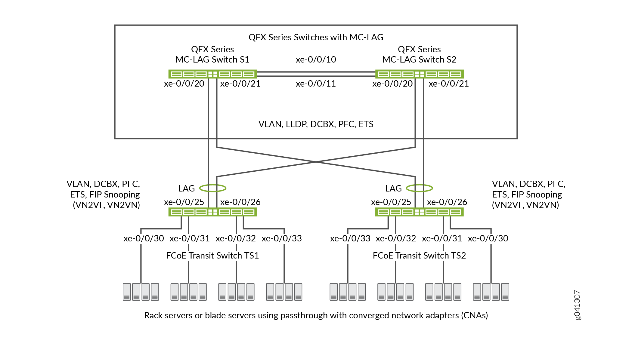
表 3 显示了此示例的配置组件。
组件 |
设置 |
|---|---|
硬件 |
四台交换机(两台用于形成 MC-LAG 作为直通中转交换机,两台中转交换机用于 FCoE 接入)。 |
转发类(所有交换机) |
默认 |
分类器(传入流量的转发类映射到 IEEE 优先级) |
所有 FCoE 接口上的默认 IEEE 802.1p 可信分类器。 |
LAG 和 MC-LAG |
S1 — 端口 xe-0/0/10 和 x-0/0/11 是 LAG ae0 的成员,用于将交换机 S1 连接到交换机 S2。端口 xe-0/0/20 和 xe-0/0/21 是 MC-LAG ae1 的成员。所有端口均配置为 S2 — 端口 xe-0/0/10 和 x-0/0/11 是 LAG ae0 的成员,用于将交换机 S2 连接到交换机 S1。端口 xe-0/0/20 和 xe-0/0/21 是 MC-LAG ae1 的成员。所有端口均配置为
注意:
交换机 S1 和 S2 上的端口 xe-0/0/20 和 xe-0/0/21 是 MC-LAG 的成员。 TS1 — 端口 xe-0/0/25 和 x-0/0/26 是 LAG ae1 的成员,在 TS2 — 端口 xe-0/0/25 和 x-0/0/26 是 LAG ae1 的成员,配置为 |
FCoE 队列调度器(所有交换机) |
|
转发类到调度器映射(所有交换机) |
调度器映射 |
转发类集(FCoE 优先级组、所有交换机) |
出口接口:
|
流量控制配置文件(所有交换机) |
|
PFC 拥塞通知配置文件(所有交换机) |
入口接口:
|
FCoE VLAN 名称和标记 ID |
姓名— 在所有四台交换机上承载 FCoE 流量的接口上包括 FCoE VLAN。 在所有四台交换机上属于 FCoE VLAN 的接口上禁用 IGMP 侦听。 |
FIP 侦听 |
在 FCoE VLAN 上的中转交换机 TS1 和 TS2 上启用 FIP 侦听。将连接到 MC-LAG 交换机的 LAG 接口配置为 FCoE 可信接口,使其不执行 FIP 侦听。 此示例可在连接到 FCoE 服务器的FCoE传输交换机接口上启用VN2VN_Port FIP 侦听。在中转交换机接入端口上启用VN2VF_Port FIP 侦听的情况下,该示例同样有效。启用的 FIP 侦听方法取决于您的网络配置。 |
此示例使用默认的 IEEE 802.1p 可信 BA 分类器,如果未应用显式配置的分类器,该分类器会自动应用于中继模式和标记接入模式端口。
要为跨 MC-LAG 的 FCoE 流量配置 CoS:
使用默认的 FCoE 转发类和转发类到队列的映射(不要显式配置 FCoE 转发类或输出队列)。默认 FCoE 转发类为
fcoe,默认输出队列为3queue 。注意:您可以在显式转发类配置中包含 无损 数据包丢弃属性,以配置无损转发类。
使用默认的可信 BA 分类器,它通过数据包的 IEEE 802.1p 代码点(CoS 优先级)将传入数据包映射到转发类。可信分类器是中继和标记访问端口模式下接口的默认分类器。默认的可信分类器将带有 IEEE 802.1p 代码点 3 (
011) 的传入数据包映射到 FCoE 转发类。如果选择配置 BA 分类器而不是使用默认分类器,则必须确保在两台 MC-LAG 交换机上以完全相同的方式将 FCoE 流量分类为转发类。使用默认分类器可确保 MC-LAG 端口上的分类器配置一致。配置一个拥塞通知配置文件,用于在 FCoE 代码点(本例中的代码点
011)上启用 PFC。两台 MC-LAG 交换机上的拥塞通知配置文件配置必须相同。将拥塞通知配置文件应用于接口。
在接口上配置增强型传输选择(ETS,也称为分层调度),以提供无损 FCoE 传输所需的带宽。配置 ETS 包括为 FCoE 转发类配置带宽调度、包含 FCoE 转发类的转发类集(优先级组)FCoE 以及用于为包含 FCoE 流量的转发类集分配带宽的流量控制配置文件。
将 ETS 调度应用于接口。
为每个接口配置端口模式、MTU 和 FCoE 可信或不可信状态,以支持无损 FCoE 传输。
此外,此示例还介绍如何在连接到 FCoE 服务器的中转交换机 TS1 和 TS2 端口上启用 FIP 侦听,以及如何禁用 FCoE VLAN 上的 IGMP 侦听。要提供安全访问,必须在 FCoE 访问端口上启用 FIP 侦听。
此示例重点介绍支持跨 MC-LAG 的无损 FCoE 传输的 CoS 配置。此示例不介绍如何配置 MC-LAG 和 LAG 的属性,但显示了如何配置支持无损传输所需的端口特性,以及如何将接口分配给 MC-LAG 和 LAG。
在配置 CoS 之前,请配置:
将交换机 S1 和 S2 连接到交换机 TS1 和 TS2 的 MC-LAG。
将中转交换机 TS1 和 TS2 连接到 MC-LAG 交换机 S1 和 S2 的 LAG。
将交换机 S1 连接到交换机 S2 的 LAG。
配置
要为跨 MC-LAG 的无损 FCoE 传输配置 CoS,请执行以下任务:
CLI 快速配置
要快速配置 CoS 以跨 MC-LAG 进行无损 FCoE 传输,请复制以下命令,将其粘贴到文本文件中,删除换行符,更改变量和详细信息以匹配您的网络配置,然后将命令复制并粘贴到层次结构级别的 [edit] MC-LAG 交换机 S1 和 MC-LAG 交换机 S2 的 CLI 中。交换机 S1 和 S2 上的配置相同,因为 CoS 配置必须相同,并且此示例在两台交换机上使用相同的端口。
交换机 S1 和交换机 S2
set class-of-service schedulers fcoe-sched priority low transmit-rate 3g set class-of-service schedulers fcoe-sched shaping-rate percent 100 set class-of-service scheduler-maps fcoe-map forwarding-class fcoe scheduler fcoe-sched set class-of-service forwarding-class-sets fcoe-pg class fcoe set class-of-service traffic-control-profiles fcoe-tcp scheduler-map fcoe-map guaranteed-rate 3g set class-of-service traffic-control-profiles fcoe-tcp shaping-rate percent 100 set class-of-service interfaces ae0 forwarding-class-set fcoe-pg output-traffic-control-profile fcoe-tcp set class-of-service interfaces ae1 forwarding-class-set fcoe-pg output-traffic-control-profile fcoe-tcp set class-of-service congestion-notification-profile fcoe-cnp input ieee-802.1 code-point 011 pfc set class-of-service interfaces ae0 congestion-notification-profile fcoe-cnp set class-of-service interfaces ae1 congestion-notification-profile fcoe-cnp set vlans fcoe_vlan vlan-id 100 set protocols igmp-snooping vlan fcoe_vlan disable set interfaces xe-0/0/10 ether-options 802.3ad ae0 set interfaces xe-0/0/11 ether-options 802.3ad ae0 set interfaces xe-0/0/20 ether-options 802.3ad ae1 set interfaces xe-0/0/21 ether-options 802.3ad ae1 set interfaces ae0 unit 0 family ethernet-switching port-mode trunk vlan members fcoe_vlan set interfaces ae1 unit 0 family ethernet-switching port-mode trunk vlan members fcoe_vlan set interfaces ae0 mtu 2180 set interfaces ae1 mtu 2180 set ethernet-switching-options secure-access-port interface ae0 fcoe-trusted set ethernet-switching-options secure-access-port interface ae1 fcoe-trusted
要快速配置 CoS 以跨 MC-LAG 进行无损 FCoE 传输,请复制以下命令,将其粘贴到文本文件中,删除换行符,更改变量和详细信息以匹配您的网络配置,然后将命令复制粘贴到层次结构级别中 [edit] 转交换机 TS1 和中转交换机 TS2 的 CLI 中。交换机 TS1 和 TS2 上的配置相同,因为 CoS 配置必须相同,并且此示例在两台交换机上使用相同的端口。
交换机 TS1 和交换机 TS2
set class-of-service schedulers fcoe-sched priority low transmit-rate 3g set class-of-service schedulers fcoe-sched shaping-rate percent 100 set class-of-service scheduler-maps fcoe-map forwarding-class fcoe scheduler fcoe-sched set class-of-service forwarding-class-sets fcoe-pg class fcoe set class-of-service traffic-control-profiles fcoe-tcp scheduler-map fcoe-map guaranteed-rate 3g set class-of-service traffic-control-profiles fcoe-tcp shaping-rate percent 100 set class-of-service interfaces ae1 forwarding-class-set fcoe-pg output-traffic-control-profile fcoe-tcp set class-of-service interfaces xe-0/0/30 forwarding-class-set fcoe-pg output-traffic-control-profile fcoe-tcp set class-of-service interfaces xe-0/0/31 forwarding-class-set fcoe-pg output-traffic-control-profile fcoe-tcp set class-of-service interfaces xe-0/0/32 forwarding-class-set fcoe-pg output-traffic-control-profile fcoe-tcp set class-of-service interfaces xe-0/0/33 forwarding-class-set fcoe-pg output-traffic-control-profile fcoe-tcp set class-of-service congestion-notification-profile fcoe-cnp input ieee-802.1 code-point 011 pfc set class-of-service interfaces ae1 congestion-notification-profile fcoe-cnp set class-of-service interfaces xe-0/0/30 congestion-notification-profile fcoe-cnp set class-of-service interfaces xe-0/0/31 congestion-notification-profile fcoe-cnp set class-of-service interfaces xe-0/0/32 congestion-notification-profile fcoe-cnp set class-of-service interfaces xe-0/0/33 congestion-notification-profile fcoe-cnp set vlans fcoe_vlan vlan-id 100 set protocols igmp-snooping vlan fcoe_vlan disable set interfaces xe-0/0/25 ether-options 802.3ad ae1 set interfaces xe-0/0/26 ether-options 802.3ad ae1 set interfaces ae1 unit 0 family ethernet-switching port-mode trunk vlan members fcoe_vlan set interfaces xe-0/0/30 unit 0 family ethernet-switching port-mode tagged-access vlan members fcoe_vlan set interfaces xe-0/0/31 unit 0 family ethernet-switching port-mode tagged-access vlan members fcoe_vlan set interfaces xe-0/0/32 unit 0 family ethernet-switching port-mode tagged-access vlan members fcoe_vlan set interfaces xe-0/0/33 unit 0 family ethernet-switching port-mode tagged-access vlan members fcoe_vlan set interfaces ae1 mtu 2180 set interfaces xe-0/0/30 mtu 2180 set interfaces xe-0/0/31 mtu 2180 set interfaces xe-0/0/32 mtu 2180 set interfaces xe-0/0/33 mtu 2180 set ethernet-switching-options secure-access-port interface ae1 fcoe-trusted set ethernet-switching-options secure-access-port vlan fcoe_vlan examine-fip examine-vn2v2 beacon-period 90000
配置 MC-LAG 交换机 S1 和 S2
分步程序
要配置 CoS 资源调度 (ETS)、PFC、FCoE VLAN 以及 LAG 和 MC-LAG 接口成员资格和特征,以支持跨 MC-LAG 的无损 FCoE 传输(此示例使用默认 fcoe 转发类和默认分类器将传入 FCoE 流量映射到 FCoE IEEE 802.1p 代码点 011,因此您无需对其进行配置):
为 FCoE 队列配置输出调度。
[edit class-of-service schedulers fcoe-sched] user@switch# set priority low transmit-rate 3g user@switch# set shaping-rate percent 100
将 FCoE 转发类映射到 FCoE 调度程序 (
fcoe-sched)。[edit class-of-service] user@switch# set scheduler-maps fcoe-map forwarding-class fcoe scheduler fcoe-sched
为 FCoE 流量配置转发类集 (
fcoe-pg)。[edit class-of-service] user@switch# set forwarding-class-sets fcoe-pg class fcoe
定义要用于 FCoE 转发类集的流量控制配置文件 (
fcoe-tcp)。[edit class-of-service traffic-control-profiles fcoe-tcp] user@switch# set scheduler-map fcoe-map guaranteed-rate 3g user@switch# set shaping-rate percent 100
将 FCoE 转发类集和流量控制配置文件应用于 LAG 和 MC-LAG 接口。
[edit class-of-service] user@switch# set interfaces ae0 forwarding-class-set fcoe-pg output-traffic-control-profile fcoe-tcp user@switch# set interfaces ae1 forwarding-class-set fcoe-pg output-traffic-control-profile fcoe-tcp
通过创建将 FCoE 应用于 IEEE 802.1 代码点
011的拥塞通知配置文件 (fcoe-cnp) ,在 FCoE 优先级上启用 FCoE 优先级的 PFC 。[edit class-of-service] user@switch# set congestion-notification-profile fcoe-cnp input ieee-802.1 code-point 011 pfc
将 PFC 配置应用于 LAG 和 MC-LAG 接口。
[edit class-of-service] user@switch# set interfaces ae0 congestion-notification-profile fcoe-cnp user@switch# set interfaces ae1 congestion-notification-profile fcoe-cnp
为 FCoE 流量配置 VLAN (
fcoe_vlan)。[edit vlans] user@switch# set fcoe_vlan vlan-id 100
禁用 FCoE VLAN 上的 IGMP 侦听。
[edit protocols] user@switch# set igmp-snooping vlan fcoe_vlan disable
将成员接口添加到两个 MC-LAG 交换机之间的 LAG。
[edit interfaces] user@switch# set xe-0/0/10 ether-options 802.3ad ae0 user@switch# set xe-0/0/11 ether-options 802.3ad ae0
将成员接口添加到 MC-LAG。
[edit interfaces] user@switch# set xe-0/0/20 ether-options 802.3ad ae1 user@switch# set xe-0/0/21 ether-options 802.3ad ae1
为 LAG (ae0) 和 MC-LAG (ae1) 配置 FCoE VLAN (
fcoe_vlan) 中的端口模式和trunk成员资格。[edit interfaces] user@switch# set ae0 unit 0 family ethernet-switching port-mode trunk vlan members fcoe_vlan user@switch# set ae1 unit 0 family ethernet-switching port-mode trunk vlan members fcoe_vlan
将 LAG 和 MC-LAG 接口的 MTU
2180设置为。由于有效负载和报头大小,2180 字节是处理 FCoE 数据包所需的最小大小。如果需要,可以将 MTU 配置为更大的字节数,但不能小于 2180 字节。
[edit interfaces] user@switch# set ae0 mtu 2180 user@switch# set ae1 mtu 2180
将 LAG 和 MC-LAG 接口设置为 FCoE 可信端口。
应信任连接到其他交换机的端口,不应执行 FIP 侦听。
[edit ethernet-switching-options secure-access-port interface] user@switch# set ae0 fcoe-trusted user@switch# set ae1 fcoe-trusted
配置 FCoE 中继交换机 TS1 和 TS2
分步程序
FCoE 中继交换机 TS1 和 TS2 上的 CoS 配置与 MC-LAG 交换机 S1 和 S2 上的 CoS 配置类似。但是,端口配置有所不同,您必须在交换机 TS1 和交换机 TS2 FCoE 接入端口上启用 FIP 侦听。
要配置资源调度 (ETS)、PFC、FCoE VLAN 以及 LAG 接口成员资格和特征,以支持跨 MC-LAG 的无损 FCoE 传输(此示例使用默认 fcoe 转发类和默认分类器将传入 FCoE 流量映射到 FCoE IEEE 802.1p 代码点 011,因此您无需对其进行配置):
为 FCoE 队列配置输出调度。
[edit class-of-service schedulers fcoe-sched] user@switch# set priority low transmit-rate 3g user@switch# set shaping-rate percent 100
将 FCoE 转发类映射到 FCoE 调度程序 (
fcoe-sched)。[edit class-of-service] user@switch# set scheduler-maps fcoe-map forwarding-class fcoe scheduler fcoe-sched
为 FCoE 流量配置转发类集 (
fcoe-pg)。[edit class-of-service] user@switch# set forwarding-class-sets fcoe-pg class fcoe
定义要用于 FCoE 转发类集的流量控制配置文件 (
fcoe-tcp)。[edit class-of-service] user@switch# set traffic-control-profiles fcoe-tcp scheduler-map fcoe-map guaranteed-rate 3g user@switch# set traffic-control-profiles fcoe-tcp shaping-rate percent 100
将 FCoE 转发类集和流量控制配置文件应用于 LAG 接口和 FCoE 接入接口。
[edit class-of-service] user@switch# set interfaces ae1 forwarding-class-set fcoe-pg output-traffic-control-profile fcoe-tcp user@switch# set interfaces xe-0/0/30 forwarding-class-set fcoe-pg output-traffic-control-profile fcoe-tcp user@switch# set interfaces xe-0/0/31 forwarding-class-set fcoe-pg output-traffic-control-profile fcoe-tcp user@switch# set interfaces xe-0/0/32 forwarding-class-set fcoe-pg output-traffic-control-profile fcoe-tcp user@switch# set interfaces xe-0/0/33 forwarding-class-set fcoe-pg output-traffic-control-profile fcoe-tcp
通过创建将 FCoE 应用于 IEEE 802.1 代码点
011的拥塞通知配置文件 (fcoe-cnp) ,在 FCoE 优先级上启用 FCoE 优先级的 PFC 。[edit class-of-service] user@switch# set congestion-notification-profile fcoe-cnp input ieee-802.1 code-point 011 pfc
将 PFC 配置应用于 LAG 接口和 FCoE 接入接口。
[edit class-of-service] user@switch# set interfaces ae1 congestion-notification-profile fcoe-cnp user@switch# set interfaces xe-0/0/30 congestion-notification-profile fcoe-cnp user@switch# set interfaces xe-0/0/31 congestion-notification-profile fcoe-cnp user@switch# set interfaces xe-0/0/32 congestion-notification-profile fcoe-cnp user@switch# set interfaces xe-0/0/33 congestion-notification-profile fcoe-cnp
为 FCoE 流量配置 VLAN (
fcoe_vlan)。[edit vlans] user@switch# set fcoe_vlan vlan-id 100
禁用 FCoE VLAN 上的 IGMP 侦听。
[edit protocols] user@switch# set igmp-snooping vlan fcoe_vlan disable
将成员接口添加到 LAG。
[edit interfaces] user@switch# set xe-0/0/25 ether-options 802.3ad ae1 user@switch# set xe-0/0/26 ether-options 802.3ad ae1
在 LAG (
ae1) 上,将端口模式配置为trunkFCoE VLANfcoe_vlan() 中的成员身份和成员资格。[edit interfaces] user@switch# set ae1 unit 0 family ethernet-switching port-mode trunk vlan members fcoe_vlan
在 FCoE 接入接口 (
xe-0/0/30、xe-0/0/32xe-0/0/31、 )xe-0/0/33上,将端口模式配置为tagged-access() 和 FCoE VLAN 中的成员资格 (fcoe_vlan)。[edit interfaces] user@switch# set xe-0/0/30 unit 0 family ethernet-switching port-mode tagged-access vlan members fcoe_vlan user@switch# set xe-0/0/31 unit 0 family ethernet-switching port-mode tagged-access vlan members fcoe_vlan user@switch# set xe-0/0/32 unit 0 family ethernet-switching port-mode tagged-access vlan members fcoe_vlan user@switch# set xe-0/0/33 unit 0 family ethernet-switching port-mode tagged-access vlan members fcoe_vlan
将 LAG 和 FCoE 接入接口的 MTU 设置为
2180。由于有效负载和报头大小,2180 字节是处理 FCoE 数据包所需的最小大小;如果需要,可以将 MTU 配置为更大的字节数,但不能少于 2180 字节。
[edit interfaces] user@switch# set ae1 mtu 2180 user@switch# set xe-0/0/30 mtu 2180 user@switch# set xe-0/0/31 mtu 2180 user@switch# set xe-0/0/32 mtu 2180 user@switch# set xe-0/0/33 mtu 2180
将 LAG 接口设置为 FCoE 可信端口。应信任连接到其他交换机的端口,不应执行 FIP 侦听:
[edit ethernet-switching-options] user@switch# set secure-access-port interface ae1 fcoe-trusted
注意:接入端口 xe-0/0/30、xe-0/0/31、xe-0/0/32 和 xe-0/0/33 未配置为 FCoE 信任端口。接入端口保持默认状态,作为不受信任的端口,因为它们直接连接到 FCoE 设备,并且必须执行 FIP 侦听以确保网络安全。
在 FCoE VLAN 上启用 FIP 侦听,以防止未经授权的FCoE网络访问(此示例使用VN2VN_Port FIP 侦听;如果使用VN2VF_Port FIP 侦听,则该示例同样有效)。
[edit ethernet-switching-options] user@switch# set secure-access-port vlan fcoe_vlan examine-fip examine-vn2vn beacon-period 90000
结果
显示 MC-LAG 交换机 S1 和 MC-LAG 交换机 S2 上的 CoS 配置结果(两台交换机上的结果相同)。
user@switch> show configuration class-of-service
traffic-control-profiles {
fcoe-tcp {
scheduler-map fcoe-map;
shaping-rate percent 100;
guaranteed-rate 3g;
}
}
forwarding-class-sets {
fcoe-pg {
class fcoe;
}
}
congestion-notification-profile {
fcoe-cnp {
input {
ieee-802.1 {
code-point 011 {
pfc;
}
}
}
}
}
interfaces {
ae0 {
forwarding-class-set {
fcoe-pg {
output-traffic-control-profile fcoe-tcp;
}
}
congestion-notification-profile fcoe-cnp;
}
ae1 {
forwarding-class-set {
fcoe-pg {
output-traffic-control-profile fcoe-tcp;
}
}
congestion-notification-profile fcoe-cnp;
}
}
scheduler-maps {
fcoe-map {
forwarding-class fcoe scheduler fcoe-sched;
}
}
schedulers {
fcoe-sched {
transmit-rate 3g;
shaping-rate percent 100;
priority low;
}
}
转发类和分类器配置不会显示,因为 show 命令不显示配置的默认部分。
显示 FCoE 中继交换机 TS1 和 FCoE 中继交换机 TS2 上的 CoS 配置结果(两个中继交换机上的结果相同)。
user@switch> show configuration class-of-service
traffic-control-profiles {
fcoe-tcp {
scheduler-map fcoe-map;
shaping-rate percent 100;
guaranteed-rate 3g;
}
}
forwarding-class-sets {
fcoe-pg {
class fcoe;
}
}
congestion-notification-profile {
fcoe-cnp {
input {
ieee-802.1 {
code-point 011 {
pfc;
}
}
}
}
}
interfaces {
xe-0/0/30 {
forwarding-class-set {
fcoe-pg {
output-traffic-control-profile fcoe-tcp;
}
}
congestion-notification-profile fcoe-cnp;
}
xe-0/0/31 {
forwarding-class-set {
fcoe-pg {
output-traffic-control-profile fcoe-tcp;
}
}
congestion-notification-profile fcoe-cnp;
}
xe-0/0/32 {
forwarding-class-set {
fcoe-pg {
output-traffic-control-profile fcoe-tcp;
}
}
congestion-notification-profile fcoe-cnp;
}
xe-0/0/33 {
forwarding-class-set {
fcoe-pg {
output-traffic-control-profile fcoe-tcp;
}
}
congestion-notification-profile fcoe-cnp;
}
ae1 {
forwarding-class-set {
fcoe-pg {
output-traffic-control-profile fcoe-tcp;
}
}
congestion-notification-profile fcoe-cnp;
}
}
scheduler-maps {
fcoe-map {
forwarding-class fcoe scheduler fcoe-sched;
}
}
schedulers {
fcoe-sched {
transmit-rate 3g;
shaping-rate percent 100;
priority low;
}
}
验证
要验证是否已配置 CoS 组件和 FIP 侦听并正常运行,请执行以下任务。由于此示例使用默认 fcoe 转发类和默认 IEEE 802.1p 可信分类器,因此不显示对这些配置的验证。
- 验证是否已创建输出队列调度程序
- 验证是否已创建优先级组输出调度器(流量控制配置文件)
- 验证转发类集(优先级组)是否已创建
- 验证是否已启用基于优先级的流控制
- 验证是否已创建接口服务等级配置
- 验证接口配置是否正确
- 验证是否在 FCoE 中转交换机 TS1 和 TS2 接入接口上的 FCoE VLAN 上启用了 FIP 侦听
- 验证 FCoE 中继交换机 TS1 和 TS2 上的 FIP 侦听模式是否正确
- 验证 FCoE VLAN 上是否已禁用 IGMP 侦听
验证是否已创建输出队列调度程序
目的
验证 FCoE 流量的输出队列调度器是否具有正确的带宽参数和优先级,并映射到正确的转发类(输出队列)。四台交换机上的队列调度器验证都是相同的。
行动
使用操作模式命令 show class-of-service scheduler-map fcoe-map列出调度器图:
user@switch> show class-of-service scheduler-map fcoe-map
Scheduler map: fcoe-map, Index: 9023
Scheduler: fcoe-sched, Forwarding class: fcoe, Index: 37289
Transmit rate: 3000000000 bps, Rate Limit: none, Buffer size: remainder,
Buffer Limit: none, Priority: low
Excess Priority: unspecified
Shaping rate: 100 percent,
drop-profile-map-set-type: mark
Drop profiles:
Loss priority Protocol Index Name
Low any 1 <default-drop-profile>
Medium high any 1 <default-drop-profile>
High any 1 <default-drop-profile>
意义
该 show class-of-service scheduler-map fcoe-map 命令列出调度器映射 fcoe-map的属性。命令输出包括:
调度器映射 (
fcoe-map) 的名称调度程序的名称 (
fcoe-sched)映射到调度程序的转发类 (
fcoe)最小保证队列带宽(传输速率
3000000000 bps)调度优先级 (
low)队列可使用的优先级组中的最大带宽(整形速率
100 percent)每个丢弃配置文件名称的丢弃配置文件丢失优先级。此示例不包括丢弃配置文件,因为您没有将丢弃配置文件应用于 FCoE 流量。
验证是否已创建优先级组输出调度器(流量控制配置文件)
目的
验证是否已使用正确的带宽参数和调度器映射创建流量控制配置文件 fcoe-tcp 。四台交换机上的优先级组调度器验证都是相同的。
行动
使用操作模式命令 show class-of-service traffic-control-profile fcoe-tcp列出 FCoE 流量控制配置文件属性:
user@switch> show class-of-service traffic-control-profile fcoe-tcp Traffic control profile: fcoe-tcp, Index: 18303 Shaping rate: 100 percent Scheduler map: fcoe-map Guaranteed rate: 3000000000
意义
该 show class-of-service traffic-control-profile fcoe-tcp 命令将列出所有配置的流量控制配置文件。对于每个流量控制配置文件,命令输出包括:
流量控制配置文件 (
fcoe-tcp) 的名称优先级组可以消耗的最大端口带宽(整形速率
100 percent)与流量控制配置文件 (
fcoe-map) 关联的调度器图最低保证优先级组端口带宽(保证速率
3000000000,以 bps 为单位)
验证转发类集(优先级组)是否已创建
目的
验证是否已创建 FCoE 优先级组,以及优先 fcoe 级(转发类)是否属于 FCoE 优先级组。四台交换机上的转发类集验证都是相同的。
行动
使用操作模式命令 show class-of-service forwarding-class-set fcoe-pg列出转发类集:
user@switch> show class-of-service forwarding-class-set fcoe-pg Forwarding class set: fcoe-pg, Type: normal-type, Forwarding class set index: 31420 Forwarding class Index fcoe 1
意义
该 show class-of-service forwarding-class-set fcoe-pg 命令列出属于优先级组的所有转发类(优先级) fcoe-pg 以及优先级组的内部索引号。命令输出显示,转发类集 fcoe-pg 包括转发类 fcoe。
验证是否已启用基于优先级的流控制
目的
验证是否在 FCoE 代码点上启用了 PFC。四台交换机上的 PFC 验证均相同。
行动
使用操作模式命令 show class-of-service congestion-notification fcoe-cnp列出 FCoE 拥塞通知配置文件:
user@switch> show class-of-service congestion-notification fcoe-cnp
Type: Input, Name: fcoe-cnp, Index: 6879
Cable Length: 100 m
Priority PFC MRU
000 Disabled
001 Disabled
010 Disabled
011 Enabled 2500
100 Disabled
101 Disabled
110 Disabled
111 Disabled
Type: Output
Priority Flow-Control-Queues
000
0
001
1
010
2
011
3
100
4
101
5
110
6
111
7
意义
该show class-of-service congestion-notification fcoe-cnp命令列出了拥塞通知配置文件中启用了 PFC 的所有 IEEE 802.1p 代码点。命令输出显示,在拥塞通知配置文件的代码点011(队列)fcoe上启用了 PFC。fcoe-cnp
该命令还显示默认电缆长度(米)、100 默认最大接收单位(2500 字节)以及优先级到输出队列的默认映射,因为此示例不包括配置这些选项。
验证是否已创建接口服务等级配置
目的
验证接口的 CoS 属性是否正确。MC-LAG 交换机 S1 和 S2 上的验证输出与 FCoE 中继交换机 TS1 和 TS2 上的输出不同。
行动
使用操作模式命令 show configuration class-of-service interfaces列出 MC-LAG 交换机 S1 和 S2 上的接口 CoS 配置:
user@switch> show configuration class-of-service interfaces
ae0 {
forwarding-class-set {
fcoe-pg {
output-traffic-control-profile fcoe-tcp;
}
}
congestion-notification-profile fcoe-cnp;
}
ae1 {
forwarding-class-set {
fcoe-pg {
output-traffic-control-profile fcoe-tcp;
}
}
congestion-notification-profile fcoe-cnp;
}
使用操作模式命令 show configuration class-of-service interfaces列出 FCoE 中继交换机 TS1 和 TS2 上的接口 CoS 配置:
user@switch> show configuration class-of-service interfaces
xe-0/0/30 {
forwarding-class-set {
fcoe-pg {
output-traffic-control-profile fcoe-tcp;
}
}
congestion-notification-profile fcoe-cnp;
}
xe-0/0/31 {
forwarding-class-set {
fcoe-pg {
output-traffic-control-profile fcoe-tcp;
}
}
congestion-notification-profile fcoe-cnp;
}
xe-0/0/32 {
forwarding-class-set {
fcoe-pg {
output-traffic-control-profile fcoe-tcp;
}
}
congestion-notification-profile fcoe-cnp;
}
xe-0/0/33 {
forwarding-class-set {
fcoe-pg {
output-traffic-control-profile fcoe-tcp;
}
}
congestion-notification-profile fcoe-cnp;
}
ae1 {
forwarding-class-set {
fcoe-pg {
output-traffic-control-profile fcoe-tcp;
}
}
congestion-notification-profile fcoe-cnp;
}
意义
该 show configuration class-of-service interfaces 命令将列出所有接口的服务等级配置。对于每个接口,命令输出包括:
接口的名称(例如,
ae0或xe-0/0/30)与接口 (
fcoe-pg) 关联的转发类集的名称与接口关联的流量控制配置文件的名称(输出流量控制配置文件、
fcoe-tcp)与接口 (
fcoe-cnp) 关联的拥塞通知配置文件的名称
作为 LAG 成员的接口不会单独显示。LAG 或 MC-LAG CoS 配置应用于属于 LAG 或 MC-LAG 成员的所有接口。例如,MC-LAG 交换机 S1 和 S2 上的接口 CoS 配置输出显示 LAG CoS 配置,但未单独显示成员接口的 CoS 配置。FCoE 中继交换机 TS1 和 TS2 上的接口 CoS 配置输出显示了 LAG CoS 配置,还显示了接口 xe-0/0/30、xe-0/0/31、xe-0/0/32 和 xe-0/0/33 的配置,这些接口不属于 LAG 成员。
验证接口配置是否正确
目的
验证接口的 LAG 成员资格、MTU、VLAN 成员资格和端口模式是否正确。MC-LAG 交换机 S1 和 S2 上的验证输出与 FCoE 中继交换机 TS1 和 TS2 上的输出不同。
行动
使用操作模式命令 show configuration interfaces列出 MC-LAG 交换机 S1 和 S2 上的接口配置:
user@switch> show configuration interfaces
xe-0/0/10 {
ether-options {
802.3ad ae0;
}
}
xe-0/0/11 {
ether-options {
802.3ad ae0;
}
}
xe-0/0/20 {
ether-options {
802.3ad ae1;
}
}
xe-0/0/21 {
ether-options {
802.3ad ae1;
}
}
ae0 {
mtu 2180;
unit 0 {
family ethernet-switching {
port-mode trunk;
vlan {
members fcoe_vlan;
}
}
}
}
ae1 {
mtu 2180;
unit 0 {
family ethernet-switching {
port-mode trunk;
vlan {
members fcoe_vlan;
}
}
}
}
使用操作模式命令 show configuration interfaces列出 FCoE 中继交换机 TS1 和 TS2 上的接口配置:
user@switch> show configuration interfaces
xe-0/0/25 {
ether-options {
802.3ad ae1;
}
}
xe-0/0/26 {
ether-options {
802.3ad ae1;
}
}
xe-0/0/30 {
mtu 2180;
unit 0 {
family ethernet-switching {
port-mode tagged-access;
vlan {
members fcoe_vlan;
}
}
}
}
xe-0/0/31 {
mtu 2180;
unit 0 {
family ethernet-switching {
port-mode tagged-access;
vlan {
members fcoe_vlan;
}
}
}
}
xe-0/0/32 {
mtu 2180;
unit 0 {
family ethernet-switching {
port-mode tagged-access;
vlan {
members fcoe_vlan;
}
}
}
}
xe-0/0/33 {
mtu 2180;
unit 0 {
family ethernet-switching {
port-mode tagged-access;
vlan {
members fcoe_vlan;
}
}
}
}
ae1 {
mtu 2180;
unit 0 {
family ethernet-switching {
port-mode trunk;
vlan {
members fcoe_vlan;
}
}
}
}
意义
该 show configuration interfaces 命令按接口名称列出每个接口的配置。
对于属于 LAG 成员的每个接口,命令仅列出接口所属 LAG 的名称。
对于每个 LAG 接口以及非 LAG 成员的每个接口,命令输出包括:
MTU (
2180)接口的单元号 (
0)端口模式(
trunk连接两台交换机的接口的模式,tagged-access连接到 FCoE 主机的接口的模式)接口所在的 VLAN 的名称 (
fcoe_vlan)
验证是否在 FCoE 中转交换机 TS1 和 TS2 接入接口上的 FCoE VLAN 上启用了 FIP 侦听
目的
验证是否在 FCoE VLAN 接入接口上启用了 FIP 侦听。FIP 侦听仅在 FCoE 接入接口上启用,因此仅在 FCoE 中继交换机 TS1 和 TS2 上启用。MC-LAG 交换机 S1 和 S2 未启用 FIP 侦听,因为 FIP 侦听是在中转交换机 TS1 和 TS2 FCoE 接入端口上完成的。
行动
使用操作模式命令 show configuration ethernet-switching-options secure-access-port列出 FCoE 中继交换机 TS1 和 TS2 上的端口安全配置:
user@switch> show configuration ethernet-switching-options secure-access-port
interface ae1.0 {
fcoe-trusted;
}
vlan fcoe_vlan {
examine-fip {
examine-vn2vn {
beacon-period 90000;
}
}
}
意义
该 show configuration ethernet-switching-options secure-access-port 命令将列出端口安全信息,包括端口是否受信任。命令输出显示:
LAG 端口
ae1.0(用于将 FCoE 中继交换机连接到 MC-LAG 交换机)配置为 FCoE 可信接口。FIP 侦听不会在 LAG 的成员接口上执行(xe-0/0/25 和 xe-0/0/26)。在 FCoE VLAN
fcoe_vlan上启用 FIP 侦听 (examine-fip),FIP 侦听的类型为VN2VN_Port FIP 侦听 (examine-vn2vn),信标周期设置为90000毫秒。在中转交换机 TS1 和 TS2 上,除非接口配置为 FCoE 信任,否则 FCoE VLAN 的所有接口成员都会执行 FIP 侦听。在传输交换机 TS1 和 TS2 上,接口 xe-0/0/30、xe-0/0/31、xe-0/0/32 和 xe-0/0/33 会执行 FIP 侦听,因为它们未配置为 FCoE 信任。LAG ae1 的接口成员(xe-0/0/25 和 xe-0/0/26)不执行 FIP 侦听,因为 LAG 配置为 FCoE 信任。
验证 FCoE 中继交换机 TS1 和 TS2 上的 FIP 侦听模式是否正确
目的
验证 FCoE VLAN 上的 FIP 侦听模式是否正确。FIP 侦听仅在 FCoE 接入接口上启用,因此仅在 FCoE 中继交换机 TS1 和 TS2 上启用。MC-LAG 交换机 S1 和 S2 未启用 FIP 侦听,因为 FIP 侦听是在中转交换机 TS1 和 TS2 FCoE 接入端口上完成的。
行动
使用操作模式命令 show fip snooping brief列出 FCoE 传输交换机 TS1 和 TS2 上的 FIP 侦听配置:
user@switch> show fip snooping brief VLAN: fcoe_vlan, Mode: VN2VN Snooping FC-MAP: 0e:fd:00 …
输出已截短,仅显示相关信息。
意义
该 show fip snooping brief 命令会列出 FIP 侦听信息,包括 FIP 侦听 VLAN 和 FIP 侦听模式。命令输出显示:
启用 FIP 侦听的 VLAN 是
fcoe_vlanFIP 侦听模式VN2VN_Port FIP 侦听 (
VN2VN Snooping)
验证 FCoE VLAN 上是否已禁用 IGMP 侦听
目的
验证是否在所有四台交换机上的 FCoE VLAN 上禁用了 IGMP 侦听。
行动
使用以下 show configuration protocols igmp-snooping 命令列出四台交换机中每台交换机上的 IGMP 侦听协议信息:
user@switch> show configuration protocols igmp-snooping
vlan fcoe_vlan {
disable;
}
意义
该 show configuration protocols igmp-snooping 命令将列出交换机上配置的 VLAN 的 IGMP 侦听配置。命令输出显示 FCoE VLAN (fcoe_vlan) 上禁用了 IGMP 侦听。
示例:EVPN-MPLS 与 MC-LAG 拓扑互连
此示例说明如何使用以太网 VPN (EVPN) 通过 MPLS 网络将多机箱链路聚合 (MC-LAG) 网络扩展到数据中心网络或地理上分散的园区网络。
EVPN-MPLS 互通由 MC-LAG 拓扑提供支持,其中两台 MX 系列路由器、两台 EX9200 交换机或两台瞻博网络设备的组合充当 MC-LAG 对等方,使用机箱间控制协议 (ICCP) 和机箱间链路 (ICL) 连接和维护拓扑。MC-LAG 对等方连接到 MPLS 网络中的提供商边缘 (PE) 设备。PE 设备可以是 MX 系列路由器,也可以是 EX9200 交换机。
此示例说明如何配置 MPLS 网络中的 MC-LAG 对等方和 PE 设备以相互通信。
要求
此示例使用以下硬件和软件组件:
三台 EX9200 交换机:
PE1 和 PE2,它们在 MC-LAG 拓扑中充当 MC-LAG 对等方,在 EVPN-MPLS 叠加网络中充当 EVPN BGP 对等方。
PE3,在 EVPN-MPLS 叠加网络中充当 EVPN BGP 对等体。
EX9200 交换机运行的是 Junos OS 17.4R1 或更高版本的软件。
尽管 MC-LAG 拓扑包括两台客户边缘 (客户边缘) 设备,但此示例重点介绍 PE1、PE2 和 PE3 的配置。
概述和拓扑
图 7 显示了 MC-LAG 拓扑,其中配置为 MC-LAG 对等方的提供商边缘设备 PE1 和 PE2。MC-LAG 对等方通过 ICCP 链路交换控制信息,并通过 ICL 交换数据流量。在此示例中,ICL 是由两个接口组成的聚合以太网接口。
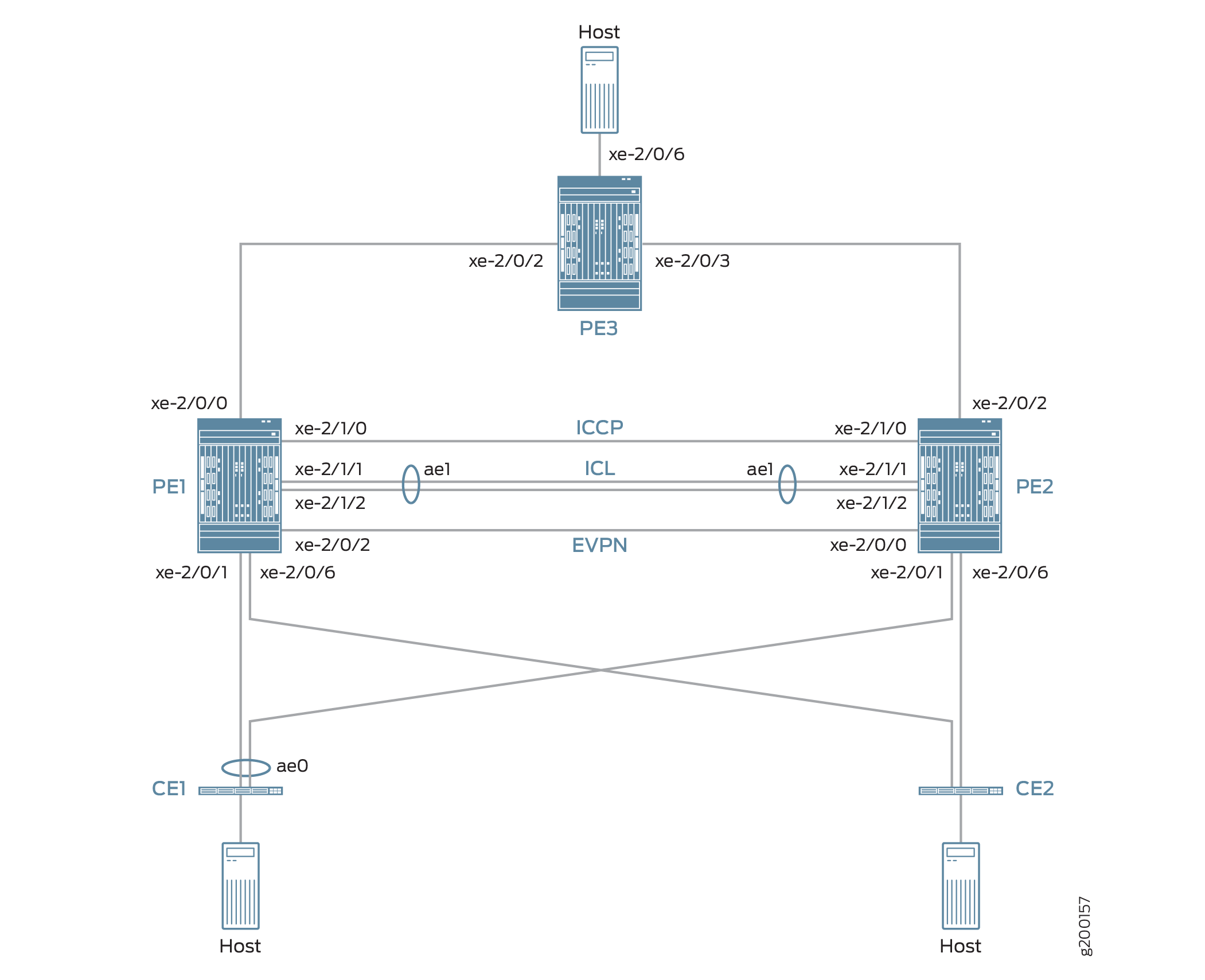 互连
互连
图 7 中的拓扑还包括客户边缘设备 CE1 和 CE2,它们都与每个 PE 设备多宿主。CE1 与两个 PE 设备之间的链路捆绑为一个聚合以太网接口,可在该接口上配置处于主动-主动模式的 MC-LAG。
图 7 中的拓扑还包括位于 MPLS 网络边缘的 PE3。PE3 充当 MC-LAG 网络与数据中心或地理上分散的园区网络之间的网关。PE1、PE2 和 PE3 运行 EVPN,使 MC-LAG 网络中的主机能够通过介于中间的 MPLS 网络与数据中心或其他园区网络中的主机进行通信。
从 EVPN-MPLS 互连功能的角度来看,PE3 仅作为 EVPN BGP 对等体运行,MC-LAG 拓扑中的 PE1 和 PE2 具有双重角色:
MC-LAG 网络中的 MC-LAG 对等方。
EVPN-MPLS 网络中的 EVPN BGP 对等方。
由于具有双重角色,PE1 和 PE2 配置了 MC-LAG、EVPN、BGP 和 MPLS 属性。
表 4 概述了在 PE1、PE2 和 PE3 上配置的关键 MC-LAG 和 EVPN(BGP 和 MPLS)属性。
关键属性 |
PE1 |
PE2 |
PE3 |
|---|---|---|---|
MC-LAG Attributes |
|||
接口 |
ICL:聚合以太网接口 ae1,由 xe-2/1/1 和 xe-2/1/2 组成 ICCP:xe-2/1/0 |
ICL:聚合以太网接口 ae1,由 xe-2/1/1 和 xe-2/1/2 组成 ICCP:xe-2/1/0 |
不适用 |
EVPN-MPLS |
|||
接口 |
与 PE3 的连接:xe-2/0/0 与 PE2 的连接:xe-2/0/2 |
与 PE3 的连接:xe-2/0/2 与 PE1 的连接:xe-2/0/0 |
与 PE1 的连接:xe-2/0/2 与 PE2 的连接:xe-2/0/3 |
IP 地址 |
BGP 对等体地址:198.51.100.1 |
BGP 对等体地址:198.51.100.2 |
BGP 对等体地址:198.51.100.3 |
自治系统 |
65000 |
65000 |
65000 |
虚拟交换机路由实例 |
EVPN1、EVPN2、EVPN3 |
EVPN1、EVPN2、EVPN3 |
EVPN1、EVPN2、EVPN3 |
请注意有关 EVPN-MPLS 互连功能及其配置的以下事项:
您必须在 MC-LAG 拓扑中的双宿主接口上配置以太网段标识符 (ESI)。ESI 使 EVPN 能够识别双宿主接口。
唯一支持的路由实例类型是虚拟交换机实例 (
set routing-instances name instance-type virtual-switch)。在 MC-LAG 对等方上,您必须将配置语句包含在
bgp-peer层次结构级别中[edit routing-instances name protocols evpn mclag]。此配置语句支持在 MC-LAG 对等方上实现 EVPN-MPLS 与 MC-LAG 的互连。不支持地址解析协议 (ARP) 抑制。
PE1 和 PE2 配置
要配置 PE1 和 PE2,请执行以下操作:
CLI 快速配置
PE1:MC-LAG 配置
set chassis aggregated-devices ethernet device-count 3 set interfaces xe-2/0/1 gigether-options 802.3ad ae0 set interfaces ae0 flexible-vlan-tagging set interfaces ae0 encapsulation flexible-ethernet-services set interfaces ae0 aggregated-ether-options lacp active set interfaces ae0 aggregated-ether-options lacp periodic fast set interfaces ae0 aggregated-ether-options lacp system-id 00:00:11:11:11:11 set interfaces ae0 aggregated-ether-options lacp admin-key 1 set interfaces ae0 aggregated-ether-options mc-ae mc-ae-id 1 set interfaces ae0 aggregated-ether-options mc-ae redundancy-group 2 set interfaces ae0 aggregated-ether-options mc-ae chassis-id 0 set interfaces ae0 aggregated-ether-options mc-ae mode active-active set interfaces ae0 aggregated-ether-options mc-ae status-control active set interfaces ae0 unit 1 esi 00:11:22:33:44:55:66:77:88:99 set interfaces ae0 unit 1 esi all-active set interfaces ae0 unit 1 family ethernet-switching interface-mode trunk set interfaces ae0 unit 1 family ethernet-switching vlan members 1 set interfaces ae0 unit 2 esi 00:11:11:11:11:11:11:11:11:11 set interfaces ae0 unit 2 esi all-active set interfaces ae0 unit 2 family ethernet-switching interface-mode trunk set interfaces ae0 unit 2 family ethernet-switching vlan members 2 set interfaces ae0 unit 3 esi 00:11:22:22:22:22:22:22:22:22 set interfaces ae0 unit 3 esi all-active set interfaces ae0 unit 3 family ethernet-switching interface-mode trunk set interfaces ae0 unit 3 family ethernet-switching vlan members 3 set interfaces xe-2/0/6 enable set interfaces xe-2/0/6 flexible-vlan-tagging set interfaces xe-2/0/6 encapsulation flexible-ethernet-services set interfaces xe-2/0/6 unit 1 family ethernet-switching interface-mode trunk set interfaces xe-2/0/6 unit 1 family ethernet-switching vlan members 1 set interfaces xe-2/0/6 unit 2 family ethernet-switching interface-mode trunk set interfaces xe-2/0/6 unit 2 family ethernet-switching vlan members 2 set interfaces xe-2/0/6 unit 3 family ethernet-switching interface-mode trunk set interfaces xe-2/0/6 unit 3 family ethernet-switching vlan members 3 set interfaces xe-2/1/0 unit 0 family inet address 203.0.113.1/24 set interfaces xe-2/1/1 gigether-options 802.3ad ae1 set interfaces xe-2/1/2 gigether-options 802.3ad ae1 set interfaces ae1 flexible-vlan-tagging set interfaces ae1 encapsulation flexible-ethernet-services set interfaces ae1 aggregated-ether-options lacp active set interfaces ae1 unit 1 family ethernet-switching interface-mode trunk set interfaces ae1 unit 1 family ethernet-switching vlan members 1 set interfaces ae1 unit 2 family ethernet-switching interface-mode trunk set interfaces ae1 unit 2 family ethernet-switching vlan members 2 set interfaces ae1 unit 3 family ethernet-switching interface-mode trunk set interfaces ae1 unit 3 family ethernet-switching vlan members 3 set multi-chassis multi-chassis-protection 203.0.113.2 interface ae1 set protocols iccp local-ip-addr 203.0.113.1 set protocols iccp peer 203.0.113.2 session-establishment-hold-time 600 set protocols iccp peer 203.0.113.2 redundancy-group-id-list 2 set protocols iccp peer 203.0.113.2 liveness-detection minimum-interval 10000 set protocols iccp peer 203.0.113.2 liveness-detection multiplier 3
PE1: EVPN-MPLS 配置
set interfaces lo0 unit 0 family inet address 198.51.100.1/32 primary set interfaces xe-2/0/0 unit 0 family inet address 192.0.2.2/24 set interfaces xe-2/0/0 unit 0 family mpls set interfaces xe-2/0/2 unit 0 family inet address 192.0.2.111/24 set interfaces xe-2/0/2 unit 0 family mpls set interfaces irb unit 1 family inet address 10.2.1.1/24 virtual-gateway-address 10.2.1.254 set interfaces irb unit 2 family inet address 10.2.2.1/24 virtual-gateway-address 10.2.2.254 set interfaces irb unit 3 family inet address 10.2.3.1/24 virtual-gateway-address 10.2.3.254 set routing-options router-id 198.51.100.1 set routing-options autonomous-system 65000 set routing-options forwarding-table export evpn-pplb set protocols mpls interface xe-2/0/0.0 set protocols mpls interface xe-2/0/2.0 set protocols bgp group evpn type internal set protocols bgp group evpn local-address 198.51.100.1 set protocols bgp group evpn family evpn signaling set protocols bgp group evpn local-as 65000 set protocols bgp group evpn neighbor 198.51.100.2 set protocols bgp group evpn neighbor 198.51.100.3 set protocols ospf area 0.0.0.0 interface lo0.0 set protocols ospf area 0.0.0.0 interface xe-2/0/0.0 set protocols ospf area 0.0.0.0 interface xe-2/0/2.0 set protocols ldp interface xe-2/0/0.0 set protocols ldp interface xe-2/0/2.0 set protocols ldp interface lo0.0 set policy-options policy-statement evpn-pplb from protocol evpn set policy-options policy-statement evpn-pplb then load-balance per-packet set routing-instances evpn1 instance-type virtual-switch set routing-instances evpn1 interface xe-2/0/6.1 set routing-instances evpn1 interface ae0.1 set routing-instances evpn1 interface ae1.1 set routing-instances evpn1 route-distinguisher 1:10 set routing-instances evpn1 vrf-target target:1:5 set routing-instances evpn1 protocols evpn extended-vlan-list 1 set routing-instances evpn1 protocols evpn mclag bgp-peer 198.51.100.2 set routing-instances evpn1 switch-options service-id 1 set routing-instances evpn1 vlans v1 vlan-id 1 set routing-instances evpn1 vlans v1 l3-interface irb.1 set routing-instances evpn2 instance-type virtual-switch set routing-instances evpn2 interface xe-2/0/6.2 set routing-instances evpn2 interface ae0.2 set routing-instances evpn2 interface ae1.2 set routing-instances evpn2 route-distinguisher 1:20 set routing-instances evpn2 vrf-target target:1:6 set routing-instances evpn2 protocols evpn extended-vlan-list 2 set routing-instances evpn2 protocols evpn mclag bgp-peer 198.51.100.2 set routing-instances evpn2 switch-options service-id 2 set routing-instances evpn2 vlans v1 vlan-id 2 set routing-instances evpn2 vlans v1 l3-interface irb.2 set routing-instances evpn3 instance-type virtual-switch set routing-instances evpn3 interface xe-2/0/6.3 set routing-instances evpn3 interface ae0.3 set routing-instances evpn3 interface ae1.3 set routing-instances evpn3 route-distinguisher 1:30 set routing-instances evpn3 vrf-target target:1:7 set routing-instances evpn3 protocols evpn extended-vlan-list 3 set routing-instances evpn3 protocols evpn mclag bgp-peer 198.51.100.2 set routing-instances evpn3 switch-options service-id 3 set routing-instances evpn3 vlans v1 vlan-id 3 set routing-instances evpn3 vlans v1 l3-interface irb.3
PE2:MC-LAG 配置
set chassis aggregated-devices ethernet device-count 3 set interfaces xe-2/0/1 gigether-options 802.3ad ae0 set interfaces xe-2/0/6 enable set interfaces xe-2/0/6 flexible-vlan-tagging set interfaces xe-2/0/6 encapsulation flexible-ethernet-services set interfaces xe-2/0/6 unit 1 family ethernet-switching interface-mode trunk set interfaces xe-2/0/6 unit 1 family ethernet-switching vlan members 1 set interfaces xe-2/0/6 unit 2 family ethernet-switching interface-mode trunk set interfaces xe-2/0/6 unit 2 family ethernet-switching vlan members 2 set interfaces xe-2/0/6 unit 3 family ethernet-switching interface-mode trunk set interfaces xe-2/0/6 unit 3 family ethernet-switching vlan members 3 set interfaces xe-2/1/0 unit 0 family inet address 203.0.113.2/24 set interfaces xe-2/1/1 gigether-options 802.3ad ae1 set interfaces xe-2/1/2 gigether-options 802.3ad ae1 set interfaces ae0 flexible-vlan-tagging set interfaces ae0 encapsulation flexible-ethernet-services set interfaces ae0 aggregated-ether-options lacp active set interfaces ae0 aggregated-ether-options lacp periodic fast set interfaces ae0 aggregated-ether-options lacp system-id 00:00:11:11:11:11 set interfaces ae0 aggregated-ether-options lacp admin-key 1 set interfaces ae0 aggregated-ether-options mc-ae mc-ae-id 1 set interfaces ae0 aggregated-ether-options mc-ae redundancy-group 2 set interfaces ae0 aggregated-ether-options mc-ae chassis-id 1 set interfaces ae0 aggregated-ether-options mc-ae mode active-active set interfaces ae0 aggregated-ether-options mc-ae status-control standby set interfaces ae0 unit 1 esi 00:11:22:33:44:55:66:77:88:99 set interfaces ae0 unit 1 esi all-active set interfaces ae0 unit 1 family ethernet-switching interface-mode trunk set interfaces ae0 unit 1 family ethernet-switching vlan members 1 set interfaces ae0 unit 2 esi 00:11:11:11:11:11:11:11:11:11 set interfaces ae0 unit 2 esi all-active set interfaces ae0 unit 2 family ethernet-switching interface-mode trunk set interfaces ae0 unit 2 family ethernet-switching vlan members 2 set interfaces ae0 unit 3 esi 00:11:22:22:22:22:22:22:22:22 set interfaces ae0 unit 3 esi all-active set interfaces ae0 unit 3 family ethernet-switching interface-mode trunk set interfaces ae0 unit 3 family ethernet-switching vlan members 3 set interfaces ae1 flexible-vlan-tagging set interfaces ae1 encapsulation flexible-ethernet-services set interfaces ae1 aggregated-ether-options lacp active set interfaces ae1 unit 1 family ethernet-switching interface-mode trunk set interfaces ae1 unit 1 family ethernet-switching vlan members 1 set interfaces ae1 unit 2 family ethernet-switching interface-mode trunk set interfaces ae1 unit 2 family ethernet-switching vlan members 2 set interfaces ae1 unit 3 family ethernet-switching interface-mode trunk set interfaces ae1 unit 3 family ethernet-switching vlan members 3 set multi-chassis multi-chassis-protection 203.0.113.1 interface ae1 set protocols iccp local-ip-addr 203.0.113.2 set protocols iccp peer 203.0.113.1 session-establishment-hold-time 600 set protocols iccp peer 203.0.113.1 redundancy-group-id-list 2 set protocols iccp peer 203.0.113.1 liveness-detection minimum-interval 10000 set protocols iccp peer 203.0.113.1 liveness-detection multiplier 3
PE2: EVPN-MPLS 配置
set interfaces xe-2/0/0 unit 0 family inet address 192.0.2.222/24 set interfaces xe-2/0/0 unit 0 family mpls set interfaces xe-2/0/2 unit 0 family inet address 192.0.2.22/24 set interfaces xe-2/0/2 unit 0 family mpls set interfaces lo0 unit 0 family inet address 198.51.100.2/32 primary set interfaces irb unit 1 family inet address 10.2.1.2/24 virtual-gateway-address 10.2.1.254 set interfaces irb unit 2 family inet address 10.2.2.2/24 virtual-gateway-address 10.2.2.254 set interfaces irb unit 3 family inet address 10.2.3.2/24 virtual-gateway-address 10.2.3.254 set routing-options router-id 198.51.100.2 set routing-options autonomous-system 65000 set routing-options forwarding-table export evpn-pplb set protocols mpls interface xe-2/0/2.0 set protocols mpls interface xe-2/0/0.0 set protocols bgp group evpn type internal set protocols bgp group evpn local-address 198.51.100.2 set protocols bgp group evpn family evpn signaling set protocols bgp group evpn local-as 65000 set protocols bgp group evpn neighbor 198.51.100.1 set protocols bgp group evpn neighbor 198.51.100.3 set protocols ospf area 0.0.0.0 interface lo0.0 set protocols ospf area 0.0.0.0 interface xe-2/0/0.0 set protocols ospf area 0.0.0.0 interface xe-2/0/2.0 set protocols ldp interface xe-2/0/0.0 set protocols ldp interface xe-2/0/2.0 set protocols ldp interface lo0.0 set policy-options policy-statement evpn-pplb from protocol evpn set policy-options policy-statement evpn-pplb then load-balance per-packet set routing-instances evpn1 instance-type virtual-switch set routing-instances evpn1 interface xe-2/0/6.1 set routing-instances evpn1 interface ae0.1 set routing-instances evpn1 interface ae1.1 set routing-instances evpn1 route-distinguisher 1:11 set routing-instances evpn1 vrf-target target:1:5 set routing-instances evpn1 protocols evpn extended-vlan-list 1 set routing-instances evpn1 protocols evpn mclag bgp-peer 198.51.100.1 set routing-instances evpn1 switch-options service-id 1 set routing-instances evpn1 vlans v1 vlan-id 1 set routing-instances evpn1 vlans v1 l3-interface irb.1 set routing-instances evpn2 instance-type virtual-switch set routing-instances evpn2 interface xe-2/0/6.2 set routing-instances evpn2 interface ae0.2 set routing-instances evpn2 interface ae1.2 set routing-instances evpn2 route-distinguisher 1:21 set routing-instances evpn2 vrf-target target:1:6 set routing-instances evpn2 protocols evpn extended-vlan-list 2 set routing-instances evpn2 protocols evpn mclag bgp-peer 198.51.100.1 set routing-instances evpn2 switch-options service-id 2 set routing-instances evpn2 vlans v1 vlan-id 2 set routing-instances evpn2 vlans v1 l3-interface irb.2 set routing-instances evpn3 instance-type virtual-switch set routing-instances evpn3 interface xe-2/0/6.3 set routing-instances evpn3 interface ae0.3 set routing-instances evpn3 interface ae1.3 set routing-instances evpn3 route-distinguisher 1:31 set routing-instances evpn3 vrf-target target:1:7 set routing-instances evpn3 protocols evpn extended-vlan-list 3 set routing-instances evpn3 protocols evpn mclag bgp-peer 198.51.100.1 set routing-instances evpn3 switch-options service-id 3 set routing-instances evpn3 vlans v1 vlan-id 3 set routing-instances evpn3 vlans v1 l3-interface irb.3
PE1:配置 MC-LAG
分步程序
设置 PE1 上的聚合以太网接口数量。
[edit] user@switch# set chassis aggregated-devices ethernet device-count 3
在接口 xe-2/0/1 上配置聚合以太网接口 ae0,并在 ae0 上配置 LACP 和 MC-LAG。将聚合以太网接口 ae0 分为三个逻辑接口(ae0.1、ae0.2 和 ae0.3)。对于每个逻辑接口,指定一个 ESI,将逻辑接口置于 MC-LAG 主动-主动模式,并将逻辑接口映射到 VLAN。
[edit] user@switch# set interfaces xe-2/0/1 gigether-options 802.3ad ae0 user@switch# set interfaces ae0 flexible-vlan-tagging user@switch# set interfaces ae0 encapsulation flexible-ethernet-services user@switch# set interfaces ae0 aggregated-ether-options lacp active user@switch# set interfaces ae0 aggregated-ether-options lacp periodic fast user@switch# set interfaces ae0 aggregated-ether-options lacp system-id 00:00:11:11:11:11 user@switch# set interfaces ae0 aggregated-ether-options lacp admin-key 1 user@switch# set interfaces ae0 aggregated-ether-options mc-ae mc-ae-id 1 user@switch# set interfaces ae0 aggregated-ether-options mc-ae redundancy-group 2 user@switch# set interfaces ae0 aggregated-ether-options mc-ae chassis-id 0 user@switch# set interfaces ae0 aggregated-ether-options mc-ae mode active-active user@switch# set interfaces ae0 aggregated-ether-options mc-ae status-control active user@switch# set interfaces ae0 unit 1 esi 00:11:22:33:44:55:66:77:88:99 user@switch# set interfaces ae0 unit 1 esi all-active user@switch# set interfaces ae0 unit 1 family ethernet-switching interface-mode trunk user@switch# set interfaces ae0 unit 1 family ethernet-switching vlan members 1 user@switch# set interfaces ae0 unit 2 esi 00:11:11:11:11:11:11:11:11:11 user@switch# set interfaces ae0 unit 2 esi all-active user@switch# set interfaces ae0 unit 2 family ethernet-switching interface-mode trunk user@switch# set interfaces ae0 unit 2 family ethernet-switching vlan members 2 user@switch# set interfaces ae0 unit 3 esi 00:11:22:22:22:22:22:22:22:22 user@switch# set interfaces ae0 unit 3 esi all-active user@switch# set interfaces ae0 unit 3 family ethernet-switching interface-mode trunk user@switch# set interfaces ae0 unit 3 family ethernet-switching vlan members 3
配置物理接口 xe-2/0/6,并将其分为三个逻辑接口(xe-2/0/6.1、xe-2/0/6.2 和 xe-2/0/6.3)。将每个逻辑接口映射到一个 VLAN。
[edit] user@switch# set interfaces xe-2/0/6 enable user@switch# set interfaces xe-2/0/6 flexible-vlan-tagging user@switch# set interfaces xe-2/0/6 encapsulation flexible-ethernet-services user@switch# set interfaces xe-2/0/6 unit 1 family ethernet-switching interface-mode trunk user@switch# set interfaces xe-2/0/6 unit 1 family ethernet-switching vlan members 1 user@switch# set interfaces xe-2/0/6 unit 2 family ethernet-switching interface-mode trunk user@switch# set interfaces xe-2/0/6 unit 2 family ethernet-switching vlan members 2 user@switch# set interfaces xe-2/0/6 unit 3 family ethernet-switching interface-mode trunk user@switch# set interfaces xe-2/0/6 unit 3 family ethernet-switching vlan members 3
将物理接口 xe-2/1/0 配置为第 3 层接口,其上配置 ICCP。将 PE2 上 IP 地址为 203.0.113.2 的接口指定为 PE1 的 ICCP 对等方。
[edit] user@switch# set interfaces xe-2/1/0 unit 0 family inet address 203.0.113.1/24 user@switch# set protocols iccp local-ip-addr 203.0.113.1 user@switch# set protocols iccp peer 203.0.113.2 session-establishment-hold-time 600 user@switch# set protocols iccp peer 203.0.113.2 redundancy-group-id-list 2 user@switch# set protocols iccp peer 203.0.113.2 liveness-detection minimum-interval 10000 user@switch# set protocols iccp peer 203.0.113.2 liveness-detection multiplier 3
在接口 xe-2/1/1 和 xe-2/1/2 上配置聚合以太网接口 ae1,并在 ae1 上配置 LACP。将聚合以太网接口 ae1 分为三个逻辑接口(ae1.1、ae1.2 和 ae1.3),并将每个逻辑接口映射到一个 VLAN。将 ae1 指定为 PE1 和 PE2 之间的多机箱保护链路。
[edit] user@switch# set interfaces xe-2/1/1 gigether-options 802.3ad ae1 user@switch# set interfaces xe-2/1/2 gigether-options 802.3ad ae1 user@switch# set interfaces ae1 flexible-vlan-tagging user@switch# set interfaces ae1 encapsulation flexible-ethernet-services user@switch# set interfaces ae1 aggregated-ether-options lacp active user@switch# set interfaces ae1 unit 1 family ethernet-switching interface-mode trunk user@switch# set interfaces ae1 unit 1 family ethernet-switching vlan members 1 user@switch# set interfaces ae1 unit 2 family ethernet-switching interface-mode trunk user@switch# set interfaces ae1 unit 2 family ethernet-switching vlan members 2 user@switch# set interfaces ae1 unit 3 family ethernet-switching interface-mode trunk user@switch# set interfaces ae1 unit 3 family ethernet-switching vlan members 3 user@switch# set multi-chassis multi-chassis-protection 203.0.113.2 interface ae1
PE1:配置 EVPN-MPLS
分步程序
配置环路接口以及连接到其他 PE 设备的接口。
[edit] user@switch# set interfaces lo0 unit 0 family inet address 198.51.100.1/32 primary user@switch# set interfaces xe-2/0/0 unit 0 family inet address 192.0.2.2/24 user@switch# set interfaces xe-2/0/0 unit 0 family mpls user@switch# set interfaces xe-2/0/2 unit 0 family inet address 192.0.2.111/24 user@switch# set interfaces xe-2/0/2 unit 0 family mpls
配置 IRB 接口 IRB.1、IRB.2 和 IRB.3。
[edit] user@switch# set interfaces irb unit 1 family inet address 10.2.1.1/24 virtual-gateway-address 10.2.1.254 user@switch# set interfaces irb unit 2 family inet address 10.2.2.1/24 virtual-gateway-address 10.2.2.254 user@switch# set interfaces irb unit 3 family inet address 10.2.3.1/24 virtual-gateway-address 10.2.3.254
分配路由器 ID 和 PE1、PE2 和 PE3 驻留的自治系统。
[edit] user@switch# set routing-options router-id 198.51.100.1 user@switch# set routing-options autonomous-system 65000
使用 EVPN 多宿主主动-主动模式时,为 EVPN 路由启用按数据包的负载均衡。
[edit] user@switch# set routing-options forwarding-table export evpn-pplb user@switch# set policy-options policy-statement evpn-pplb from protocol evpn user@switch# set policy-options policy-statement evpn-pplb then load-balance per-packet
在接口 xe-2/0/0.0 和 xe-2/0/2.0 上启用 MPLS。
[edit] user@switch# set protocols mpls interface xe-2/0/0.0 user@switch# set protocols mpls interface xe-2/0/2.0
配置包含 PE1、PE2 和 PE3 的 IBGP 叠加。
[edit] user@switch# set protocols bgp group evpn type internal user@switch# set protocols bgp group evpn local-address 198.51.100.1 user@switch# set protocols bgp group evpn family evpn signaling user@switch# set protocols bgp group evpn local-as 65000 user@switch# set protocols bgp group evpn neighbor 198.51.100.2 user@switch# set protocols bgp group evpn neighbor 198.51.100.3
通过指定启用 EVPN-MPLS 的区域 ID 和接口,将 OSPF 配置为 EVPN 的内部路由协议。
[edit] user@switch# set protocols ospf area 0.0.0.0 interface lo0.0 user@switch# set protocols ospf area 0.0.0.0 interface xe-2/0/0.0 user@switch# set protocols ospf area 0.0.0.0 interface xe-2/0/2.0
在环路接口和启用 EVPN-MPLS 的接口上配置标签分发协议 (LDP)。
[edit] user@switch# set protocols ldp interface lo0.0 user@switch# set protocols ldp interface xe-2/0/0.0 user@switch# set protocols ldp interface xe-2/0/2.0
为 VLAN v1 配置虚拟交换机路由实例,其分配的 VLAN ID 为 1、2 和 3,包括与 VLAN 关联的接口和其他实体。
[edit] user@switch# set routing-instances evpn1 instance-type virtual-switch user@switch# set routing-instances evpn1 interface xe-2/0/6.1 user@switch# set routing-instances evpn1 interface ae0.1 user@switch# set routing-instances evpn1 interface ae1.1 user@switch# set routing-instances evpn1 route-distinguisher 1:10 user@switch# set routing-instances evpn1 vrf-target target:1:5 user@switch# set routing-instances evpn1 protocols evpn extended-vlan-list 1 user@switch# set routing-instances evpn1 protocols evpn mclag bgp-peer 198.51.100.2 user@switch# set routing-instances evpn1 switch-options service-id 1 user@switch# set routing-instances evpn1 vlans v1 vlan-id 1 user@switch# set routing-instances evpn1 vlans v1 l3-interface irb.1 user@switch# set routing-instances evpn2 instance-type virtual-switch user@switch# set routing-instances evpn2 interface xe-2/0/6.2 user@switch# set routing-instances evpn2 interface ae0.2 user@switch# set routing-instances evpn2 interface ae1.2 user@switch# set routing-instances evpn2 route-distinguisher 1:20 user@switch# set routing-instances evpn2 vrf-target target:1:6 user@switch# set routing-instances evpn2 protocols evpn extended-vlan-list 2 user@switch# set routing-instances evpn2 protocols evpn mclag bgp-peer 198.51.100.2 user@switch# set routing-instances evpn2 switch-options service-id 2 user@switch# set routing-instances evpn2 vlans v1 vlan-id 2 user@switch# set routing-instances evpn2 vlans v1 l3-interface irb.2 user@switch# set routing-instances evpn3 instance-type virtual-switch user@switch# set routing-instances evpn3 interface xe-2/0/6.3 user@switch# set routing-instances evpn3 interface ae0.3 user@switch# set routing-instances evpn3 interface ae1.3 user@switch# set routing-instances evpn3 route-distinguisher 1:30 user@switch# set routing-instances evpn3 vrf-target target:1:7 user@switch# set routing-instances evpn3 protocols evpn extended-vlan-list 3 user@switch# set routing-instances evpn3 protocols evpn mclag bgp-peer 198.51.100.2 user@switch# set routing-instances evpn3 switch-options service-id 3 user@switch# set routing-instances evpn3 vlans v1 vlan-id 3 user@switch# set routing-instances evpn3 vlans v1 l3-interface irb.3
PE2:配置 MC-LAG
分步程序
设置 PE2 上的聚合以太网接口数量。
[edit] user@switch# set chassis aggregated-devices ethernet device-count 3
在接口 xe-2/0/1 上配置聚合以太网接口 ae0,并在 ae0 上配置 LACP 和 MC-LAG。将聚合以太网接口 ae0 分为三个逻辑接口(ae0.1、ae0.2 和 ae0.3)。对于每个逻辑接口,指定一个 ESI,将逻辑接口置于 MC-LAG 主动-主动模式,并将逻辑接口映射到 VLAN。
[edit] user@switch# set interfaces xe-2/0/1 gigether-options 802.3ad ae0 user@switch# set interfaces ae0 flexible-vlan-tagging user@switch# set interfaces ae0 encapsulation flexible-ethernet-services user@switch# set interfaces ae0 aggregated-ether-options lacp active user@switch# set interfaces ae0 aggregated-ether-options lacp periodic fast user@switch# set interfaces ae0 aggregated-ether-options lacp system-id 00:00:11:11:11:11 user@switch# set interfaces ae0 aggregated-ether-options lacp admin-key 1 user@switch# set interfaces ae0 aggregated-ether-options mc-ae mc-ae-id 1 user@switch# set interfaces ae0 aggregated-ether-options mc-ae redundancy-group 2 user@switch# set interfaces ae0 aggregated-ether-options mc-ae chassis-id 1 user@switch# set interfaces ae0 aggregated-ether-options mc-ae mode active-active user@switch# set interfaces ae0 aggregated-ether-options mc-ae status-control standby user@switch# set interfaces ae0 unit 1 esi 00:11:22:33:44:55:66:77:88:99 user@switch# set interfaces ae0 unit 1 esi all-active user@switch# set interfaces ae0 unit 1 family ethernet-switching interface-mode trunk user@switch# set interfaces ae0 unit 1 family ethernet-switching vlan members 1 user@switch# set interfaces ae0 unit 2 esi 00:11:11:11:11:11:11:11:11:11 user@switch# set interfaces ae0 unit 2 esi all-active user@switch# set interfaces ae0 unit 2 family ethernet-switching interface-mode trunk user@switch# set interfaces ae0 unit 2 family ethernet-switching vlan members 2 user@switch# set interfaces ae0 unit 3 esi 00:11:22:22:22:22:22:22:22:22 user@switch# set interfaces ae0 unit 3 esi all-active user@switch# set interfaces ae0 unit 3 family ethernet-switching interface-mode trunk user@switch# set interfaces ae0 unit 3 family ethernet-switching vlan members 3
配置物理接口 xe-2/0/6,并将其分为三个逻辑接口(xe-2/0/6.1、xe-2/0/6.2 和 xe-2/0/6.3)。将每个逻辑接口映射到一个 VLAN。
[edit] set interfaces xe-2/0/6 enable set interfaces xe-2/0/6 flexible-vlan-tagging set interfaces xe-2/0/6 encapsulation flexible-ethernet-services set interfaces xe-2/0/6 unit 1 family ethernet-switching interface-mode trunk set interfaces xe-2/0/6 unit 1 family ethernet-switching vlan members 1 set interfaces xe-2/0/6 unit 2 family ethernet-switching interface-mode trunk set interfaces xe-2/0/6 unit 2 family ethernet-switching vlan members 2 set interfaces xe-2/0/6 unit 3 family ethernet-switching interface-mode trunk set interfaces xe-2/0/6 unit 3 family ethernet-switching vlan members 3
将物理接口 xe-2/1/0 配置为第 3 层接口,其上配置 ICCP。将 PE1 上 IP 地址为 203.0.113.1 的接口指定为 PE2 的 ICCP 对等方。
[edit] set interfaces xe-2/1/0 unit 0 family inet address 203.0.113.2/24 set protocols iccp local-ip-addr 203.0.113.2 set protocols iccp peer 203.0.113.1 session-establishment-hold-time 600 set protocols iccp peer 203.0.113.1 redundancy-group-id-list 2 set protocols iccp peer 203.0.113.1 liveness-detection minimum-interval 10000 set protocols iccp peer 203.0.113.1 liveness-detection multiplier 3
在接口 xe-2/1/1 和 xe-2/1/2 上配置聚合以太网接口 ae1,并在 ae1 上配置 LACP。将聚合以太网接口 ae1 分为三个逻辑接口(ae1.1、ae1.2 和 ae1.3),并将每个逻辑接口映射到一个 VLAN。将 ae1 指定为 PE1 和 PE2 之间的多机箱保护链路。
[edit] set interfaces xe-2/1/1 gigether-options 802.3ad ae1 set interfaces xe-2/1/2 gigether-options 802.3ad ae1 set interfaces ae1 flexible-vlan-tagging set interfaces ae1 encapsulation flexible-ethernet-services set interfaces ae1 aggregated-ether-options lacp active set interfaces ae1 unit 1 family ethernet-switching interface-mode trunk set interfaces ae1 unit 1 family ethernet-switching vlan members 1 set interfaces ae1 unit 2 family ethernet-switching interface-mode trunk set interfaces ae1 unit 2 family ethernet-switching vlan members 2 set interfaces ae1 unit 3 family ethernet-switching interface-mode trunk set interfaces ae1 unit 3 family ethernet-switching vlan members 3 set multi-chassis multi-chassis-protection 203.0.113.1 interface ae1
PE2:配置 EVPN-MPLS
分步程序
配置环路接口以及连接到其他 PE 设备的接口。
[edit] user@switch# set interfaces lo0 unit 0 family inet address 198.51.100.2/32 primary user@switch# set interfaces xe-2/0/0 unit 0 family inet address 192.0.2.222/24 user@switch# set interfaces xe-2/0/0 unit 0 family mpls user@switch# set interfaces xe-2/0/2 unit 0 family inet address 192.0.2.22/24 user@switch# set interfaces xe-2/0/2 unit 0 family mpls
配置 IRB 接口 IRB.1、IRB.2 和 IRB.3。
[edit] user@switch# set interfaces irb unit 1 family inet address 10.2.1.2/24 virtual-gateway-address 10.2.1.254 user@switch# set interfaces irb unit 2 family inet address 10.2.2.2/24 virtual-gateway-address 10.2.2.254 user@switch# set interfaces irb unit 3 family inet address 10.2.3.2/24 virtual-gateway-address 10.2.3.254
分配路由器 ID 和 PE1、PE2 和 PE3 驻留的自治系统。
[edit] user@switch# set routing-options router-id 198.51.100.2 user@switch# set routing-options autonomous-system 65000
使用 EVPN 多宿主主动-主动模式时,为 EVPN 路由启用按数据包的负载均衡。
[edit] user@switch# set routing-options forwarding-table export evpn-pplb user@switch# set policy-options policy-statement evpn-pplb from protocol evpn user@switch# set policy-options policy-statement evpn-pplb then load-balance per-packet
在接口 xe-2/0/0.0 和 xe-2/0/2.0 上启用 MPLS。
[edit] user@switch# set protocols mpls interface xe-2/0/0.0 user@switch# set protocols mpls interface xe-2/0/2.0
配置包含 PE1、PE2 和 PE3 的 IBGP 叠加。
[edit] user@switch# set protocols bgp group evpn type internal user@switch# set protocols bgp group evpn local-address 198.51.100.2 user@switch# set protocols bgp group evpn family evpn signaling user@switch# set protocols bgp group evpn local-as 65000 user@switch# set protocols bgp group evpn neighbor 198.51.100.1 user@switch# set protocols bgp group evpn neighbor 198.51.100.3
通过指定启用 EVPN-MPLS 的区域 ID 和接口,将 OSPF 配置为 EVPN 的内部路由协议。
[edit] user@switch# set protocols ospf area 0.0.0.0 interface lo0.0 user@switch# set protocols ospf area 0.0.0.0 interface xe-2/0/0.0 user@switch# set protocols ospf area 0.0.0.0 interface xe-2/0/2.0
在环路接口和启用 EVPN-MPLS 的接口上配置标签分发协议 (LDP)。
[edit] user@switch# set protocols ldp interface lo0.0 user@switch# set protocols ldp interface xe-2/0/0.0 user@switch# set protocols ldp interface xe-2/0/2.0
为 VLAN v1 配置虚拟交换机路由实例,其分配的 VLAN ID 为 1、2 和 3,包括与 VLAN 关联的接口和其他实体。
[edit] user@switch# set routing-instances evpn1 instance-type virtual-switch user@switch# set routing-instances evpn1 interface xe-2/0/6.1 user@switch# set routing-instances evpn1 interface ae0.1 user@switch# set routing-instances evpn1 interface ae1.1 user@switch# set routing-instances evpn1 route-distinguisher 1:11 user@switch# set routing-instances evpn1 vrf-target target:1:5 user@switch# set routing-instances evpn1 protocols evpn extended-vlan-list 1 user@switch# set routing-instances evpn1 protocols evpn mclag bgp-peer 198.51.100.1 user@switch# set routing-instances evpn1 switch-options service-id 1 user@switch# set routing-instances evpn1 vlans v1 vlan-id 1 user@switch# set routing-instances evpn1 vlans v1 l3-interface irb.1 user@switch# set routing-instances evpn2 instance-type virtual-switch user@switch# set routing-instances evpn2 interface xe-2/0/6.2 user@switch# set routing-instances evpn2 interface ae0.2 user@switch# set routing-instances evpn2 interface ae1.2 user@switch# set routing-instances evpn2 route-distinguisher 1:21 user@switch# set routing-instances evpn2 vrf-target target:1:6 user@switch# set routing-instances evpn2 protocols evpn extended-vlan-list 2 user@switch# set routing-instances evpn2 protocols evpn mclag bgp-peer 198.51.100.1 user@switch# set routing-instances evpn2 switch-options service-id 2 user@switch# set routing-instances evpn2 vlans v1 vlan-id 2 user@switch# set routing-instances evpn2 vlans v1 l3-interface irb.2 user@switch# set routing-instances evpn3 instance-type virtual-switch user@switch# set routing-instances evpn3 interface xe-2/0/6.3 user@switch# set routing-instances evpn3 interface ae0.3 user@switch# set routing-instances evpn3 interface ae1.3 user@switch# set routing-instances evpn3 route-distinguisher 1:31 user@switch# set routing-instances evpn3 vrf-target target:1:7 user@switch# set routing-instances evpn3 protocols evpn extended-vlan-list 3 user@switch# set routing-instances evpn3 protocols evpn mclag bgp-peer 198.51.100.1 user@switch# set routing-instances evpn3 switch-options service-id 3 user@switch# set routing-instances evpn3 vlans v1 vlan-id 3 user@switch# set routing-instances evpn3 vlans v1 l3-interface irb.3
PE3 配置
CLI 快速配置
PE3: EVPN-MPLS 配置
set interfaces lo0 unit 0 family inet address 198.51.100.3/32 primary set interfaces xe-2/0/2 unit 0 family inet address 192.0.2.1/24 set interfaces xe-2/0/2 unit 0 family mpls set interfaces xe-2/0/3 unit 0 family inet address 192.0.2.11/24 set interfaces xe-2/0/3 unit 0 family mpls set interfaces xe-2/0/6 enable set interfaces xe-2/0/6 flexible-vlan-tagging set interfaces xe-2/0/6 encapsulation flexible-ethernet-services set interfaces xe-2/0/6 unit 1 family ethernet-switching interface-mode trunk set interfaces xe-2/0/6 unit 1 family ethernet-switching vlan members 1 set interfaces xe-2/0/6 unit 2 family ethernet-switching interface-mode trunk set interfaces xe-2/0/6 unit 2 family ethernet-switching vlan members 2 set interfaces xe-2/0/6 unit 3 family ethernet-switching interface-mode trunk set interfaces xe-2/0/6 unit 3 family ethernet-switching vlan members 3 set interfaces irb unit 1 family inet address 10.2.1.3/24 virtual-gateway-address 10.2.1.254 set interfaces irb unit 2 family inet address 10.2.2.3/24 virtual-gateway-address 10.2.2.254 set interfaces irb unit 3 family inet address 10.2.3.3/24 virtual-gateway-address 10.2.3.254 set routing-options router-id 198.51.100.3 set routing-options autonomous-system 65000 set routing-options forwarding-table export evpn-pplb set protocols mpls interface xe-2/0/2.0 set protocols mpls interface xe-2/0/3.0 set protocols bgp group evpn type internal set protocols bgp group evpn local-address 198.51.100.3 set protocols bgp group evpn family evpn signaling set protocols bgp group evpn local-as 65000 set protocols bgp group evpn neighbor 198.51.100.1 set protocols bgp group evpn neighbor 198.51.100.2 set protocols ospf area 0.0.0.0 interface lo0.0 set protocols ospf area 0.0.0.0 interface xe-2/0/2.0 set protocols ospf area 0.0.0.0 interface xe-2/0/3.0 set protocols ldp interface lo0.0 set protocols ldp interface xe-2/0/2.0 set protocols ldp interface xe-2/0/3.0 set policy-options policy-statement evpn-pplb from protocol evpn set policy-options policy-statement evpn-pplb then load-balance per-packet set routing-instances evpn1 instance-type virtual-switch set routing-instances evpn1 interface xe-2/0/6.1 set routing-instances evpn1 route-distinguisher 1:12 set routing-instances evpn1 vrf-target target:1:5 set routing-instances evpn1 protocols evpn extended-vlan-list 1 set routing-instances evpn1 switch-options service-id 1 set routing-instances evpn1 vlans v1 vlan-id 1 set routing-instances evpn1 vlans v1 l3-interface irb.1 set routing-instances evpn2 instance-type virtual-switch set routing-instances evpn2 interface xe-2/0/6.2 set routing-instances evpn2 route-distinguisher 1:22 set routing-instances evpn2 vrf-target target:1:6 set routing-instances evpn2 protocols evpn extended-vlan-list 2 set routing-instances evpn2 switch-options service-id 2 set routing-instances evpn2 vlans v1 vlan-id 2 set routing-instances evpn2 vlans v1 l3-interface irb.2 set routing-instances evpn3 instance-type virtual-switch set routing-instances evpn3 interface xe-2/0/6.3 set routing-instances evpn3 route-distinguisher 1:32 set routing-instances evpn3 vrf-target target:1:7 set routing-instances evpn3 protocols evpn extended-vlan-list 3 set routing-instances evpn3 switch-options service-id 3 set routing-instances evpn3 vlans v1 vlan-id 3 set routing-instances evpn3 vlans v1 l3-interface irb.3
PE3:配置 EVPN-MPLS
分步程序
配置环路接口以及连接到其他 PE 设备的接口。
[edit] user@switch# set interfaces lo0 unit 0 family inet address 198.51.100.3/32 primary user@switch# set interfaces xe-2/0/2 unit 0 family inet address 192.0.2.1/24 user@switch# set interfaces xe-2/0/2 unit 0 family mpls user@switch# set interfaces xe-2/0/3 unit 0 family inet address 192.0.2.11/24 user@switch# set interfaces xe-2/0/3 unit 0 family mpls
配置连接到主机的接口 xe-2/0/6。
[edit] user@switch# set interfaces xe-2/0/6 enable user@switch# set interfaces xe-2/0/6 flexible-vlan-tagging user@switch# set interfaces xe-2/0/6 encapsulation flexible-ethernet-services user@switch# set interfaces xe-2/0/6 unit 1 family ethernet-switching interface-mode trunk user@switch# set interfaces xe-2/0/6 unit 1 family ethernet-switching vlan members 1 user@switch# set interfaces xe-2/0/6 unit 2 family ethernet-switching interface-mode trunk user@switch# set interfaces xe-2/0/6 unit 2 family ethernet-switching vlan members 2 user@switch# set interfaces xe-2/0/6 unit 3 family ethernet-switching interface-mode trunk user@switch# set interfaces xe-2/0/6 unit 3 family ethernet-switching vlan members 3
配置 IRB 接口 IRB.1、IRB.2 和 IRB.3。
[edit] user@switch# set interfaces irb unit 1 family inet address 10.2.1.3/24 virtual-gateway-address 10.2.1.254 user@switch# set interfaces irb unit 2 family inet address 10.2.2.3/24 virtual-gateway-address 10.2.2.254 user@switch# set interfaces irb unit 3 family inet address 10.2.3.3/24 virtual-gateway-address 10.2.3.254
分配路由器 ID 和 PE1、PE2 和 PE3 驻留的自治系统。
[edit] user@switch# set routing-options router-id 198.51.100.3 user@switch# set routing-options autonomous-system 65000
使用 EVPN 多宿主主动-主动模式时,为 EVPN 路由启用按数据包的负载均衡。
[edit] user@switch# set routing-options forwarding-table export evpn-pplb user@switch# set policy-options policy-statement evpn-pplb from protocol evpn user@switch# set policy-options policy-statement evpn-pplb then load-balance per-packet
在接口 xe-2/0/2.0 和 xe-2/0/3.0 上启用 MPLS。
[edit] user@switch# set protocols mpls interface xe-2/0/2.0 user@switch# set protocols mpls interface xe-2/0/3.0
配置包含 PE1、PE2 和 PE3 的 IBGP 叠加。
[edit] user@switch# set protocols bgp group evpn type internal user@switch# set protocols bgp group evpn local-address 198.51.100.3 user@switch# set protocols bgp group evpn family evpn signaling user@switch# set protocols bgp group evpn local-as 65000 user@switch# set protocols bgp group evpn neighbor 198.51.100.1 user@switch# set protocols bgp group evpn neighbor 198.51.100.2
通过指定启用 EVPN-MPLS 的区域 ID 和接口,将 OSPF 配置为 EVPN 的内部路由协议。
[edit] user@switch# set protocols ospf area 0.0.0.0 interface lo0.0 user@switch# set protocols ospf area 0.0.0.0 interface xe-2/0/2.0 user@switch# set protocols ospf area 0.0.0.0 interface xe-2/0/3.0
在环路接口和启用 EVPN-MPLS 的接口上配置 LDP。
[edit] user@switch# set protocols ldp interface lo0.0 user@switch# set protocols ldp interface xe-2/0/2.0 user@switch# set protocols ldp interface xe-2/0/3.0
为 VLAN v1 配置虚拟交换机路由实例,其分配的 VLAN ID 为 1、2 和 3,包括与 VLAN 关联的接口和其他实体。
[edit] user@switch# set routing-instances evpn1 instance-type virtual-switch user@switch# set routing-instances evpn1 interface xe-2/0/6.1 user@switch# set routing-instances evpn1 route-distinguisher 1:12 user@switch# set routing-instances evpn1 vrf-target target:1:5 user@switch# set routing-instances evpn1 protocols evpn extended-vlan-list 1 user@switch# set routing-instances evpn1 switch-options service-id 1 user@switch# set routing-instances evpn1 vlans v1 vlan-id 1 user@switch# set routing-instances evpn1 vlans v1 l3-interface irb.1 user@switch# set routing-instances evpn2 instance-type virtual-switch user@switch# set routing-instances evpn2 interface xe-2/0/6.2 user@switch# set routing-instances evpn2 route-distinguisher 1:22 user@switch# set routing-instances evpn2 vrf-target target:1:6 user@switch# set routing-instances evpn2 protocols evpn extended-vlan-list 2 user@switch# set routing-instances evpn2 switch-options service-id 2 user@switch# set routing-instances evpn2 vlans v1 vlan-id 2 user@switch# set routing-instances evpn2 vlans v1 l3-interface irb.2 user@switch# set routing-instances evpn3 instance-type virtual-switch user@switch# set routing-instances evpn3 interface xe-2/0/6.3 user@switch# set routing-instances evpn3 route-distinguisher 1:32 user@switch# set routing-instances evpn3 vrf-target target:1:7 user@switch# set routing-instances evpn3 protocols evpn extended-vlan-list 3 user@switch# set routing-instances evpn3 switch-options service-id 3 user@switch# set routing-instances evpn3 vlans v1 vlan-id 3 user@switch# set routing-instances evpn3 vlans v1 l3-interface irb.3