逻辑系统上的防火墙过滤器
防火墙过滤器提供定义接受或丢弃正在通过接口的数据包的规则。有关更多信息,请参阅以下主题:
了解如何使用标准防火墙过滤器
使用标准防火墙过滤器影响本地数据包
在路由器上,您可以在接口上配置一个物理回传接口、 lo0 和一个或多个地址。环路接口是路由引擎的接口,用于运行和监控所有控制协议。回传接口仅承载本地数据包。应用于环路接口的标准防火墙过滤器会影响从路由引擎发送或传输的本地数据包。
创建附加环路接口时,必须将其应用过滤器,以便保护路由引擎。建议在将过滤器应用到环路接口时,应包含 应用组 语句。这样可确保过滤器在每个回传接口(包括 lo0 和其他回传接口)上自动继承。
可信来源
标准无状态 防火墙过滤器 的典型用途是保护路由引擎进程和资源免受恶意或不受信任的数据包的影响。为了保护路由引擎拥有的进程和资源,您可以使用标准的无状态防火墙过滤器来指定哪些协议和服务或应用程序可以到达路由引擎。将这种类型的过滤器应用于环路接口可确保本地数据包来自可信源,并保护路由引擎上运行的进程免遭外部攻击。
防洪
您可以创建标准的无状态防火墙过滤器,以限制某些发往路由引擎的 TCP 和 ICMP 流量。没有这种保护的路由器容易受到 TCP 和 ICMP 泛滥攻击,这些攻击也称为拒绝服务 (DoS) 攻击。例如:
启动连接请求的 SYN 数据包的 TCP 泛滥攻击会使设备不堪重负,直至其无法再处理合法连接请求,从而导致服务拒绝。
ICMP 泛洪会使设备因大量回应请求(ping 请求)而过载,以至于它消耗了所有资源来响应,无法再处理有效的网络流量,也导致拒绝服务。
将适当的防火墙过滤器应用于路由引擎可防止此类攻击。
使用标准防火墙过滤器影响数据包
适用于路由器传输接口的标准防火墙过滤器仅评估从一个接口直接传输到另一个接口的用户数据包,因为它们正从来源转发至目标。为了保护整个网络免受特定接口的未经授权访问和其他威胁,您可以应用防火墙过滤器路由器中转接口。
另请参阅
示例:配置无状态防火墙过滤器以保护逻辑系统免受 ICMP 泛滥
此示例说明如何配置可防止逻辑系统上 ICMP 拒绝服务攻击的无状态防火墙过滤器。
要求
在此示例中,除了设备初始化之外,不需要特殊配置。
概述
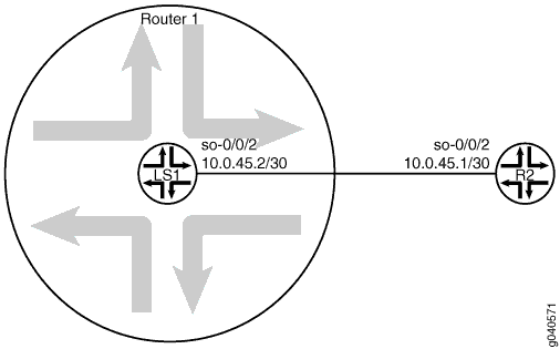
此示例显示称为 Protect-RE 的无状态防火墙过滤器,用于监管 ICMP 数据包。将 icmp-policer ICMP 数据包的流量速率限制为 1,000,000 bps,突发大小限制为 15,000 字节。超过信息流速的数据包将被丢弃。
监管器被纳入一个过滤器术语的操作中,称为 icmp-term。
在此示例中,ping 将从直接连接的物理路由器发送至逻辑系统上配置的接口。如果以高达 1 Mbps(带宽限制)的速率接收 ICMP 数据包,逻辑系统将接受这些数据包。超过此速率时,逻辑系统将丢弃所有 ICMP 数据包。该 burst-size-limit 语句接受高达 15 Kbps 的信息流突发。如果突发超过此限制,则所有数据包均会被丢弃。当流速下降时,再次接受 ICMP 数据包。
配置
CLI 快速配置
要快速配置此示例,请复制以下命令,将其粘贴到文本文件中,移除任何换行符,更改与网络配置匹配所需的任何详细信息,然后将命令复制粘贴到层次结构级别的 [edit] CLI 中。
set logical-systems LS1 interfaces so-0/0/2 unit 0 family inet policer input icmp-policer
set logical-systems LS1 interfaces so-0/0/2 unit 0 family inet address 10.0.45.2/30
set logical-systems LS1 firewall family inet filter protect-RE term icmp-term from protocol icmp
set logical-systems LS1 firewall family inet filter protect-RE term icmp-term then policer icmp-policer
set logical-systems LS1 firewall family inet filter protect-RE term icmp-term then accept
set logical-systems LS1 firewall policer icmp-policer if-exceeding bandwidth-limit 1m
set logical-systems LS1 firewall policer icmp-policer if-exceeding burst-size-limit 15k
set logical-systems LS1 firewall policer icmp-policer then discard
程序
逐步过程
以下示例要求您在配置层次结构中导航各个级别。有关导航 CLI 的信息,请参阅 CLI 用户指南中的配置模式下使用 CLI 编辑器。
要在逻辑系统上配置 ICMP 防火墙过滤器:
在逻辑系统上配置接口。
[edit]
user@host# set logical-systems LS1 interfaces so-0/0/2 unit 0 family inet address 10.0.45.2/30
明确允许在接口上接收 ICMP 数据包。
[edit]
user@host# set logical-systems LS1 firewall family inet filter protect-RE term icmp-term from protocol icmp
user@host# set logical-systems LS1 firewall family inet filter protect-RE term icmp-term then accept
创建监管器。
[edit]
user@host# set logical-systems LS1 firewall policer icmp-policer if-exceeding bandwidth-limit 1m
user@host# set logical-systems LS1 firewall policer icmp-policer if-exceeding burst-size-limit 15k
user@host# set logical-systems LS1 firewall policer icmp-policer then discard
将监管器应用到过滤器术语。
[edit]
user@host# set logical-systems LS1 firewall family inet filter protect-RE term icmp-term then policer icmp-policer
将监管器应用到逻辑系统接口。
[edit]
user@host# set logical-systems LS1 interfaces so-0/0/2 unit 0 family inet policer input icmp-policer
如果完成设备配置,请提交配置。
[edit]
user@host# commit
结果
发出 命令以 show logical-systems LS1 确认您的配置。
user@host# show logical-systems LS1
interfaces {
    so-0/0/2 {
        unit 0 {
            family inet {
                policer {
                    input icmp-policer;
                }
                address 10.0.45.2/30;
            }
        }
    }
}
firewall {
    family inet {
        filter protect-RE {
            term icmp-term {
                from {
                    protocol icmp;
                }
                then {
                    policer icmp-policer;
                    accept;
                }
            }
        }
    }
    policer icmp-policer {
        if-exceeding {
            bandwidth-limit 1m;
            burst-size-limit 15k;
        }
        then discard;
    }
}
验证
确认配置工作正常。
验证 Ping 是否工作,除非超出限制
目的
确保逻辑系统接口受到基于 ICMP 的 DoS 攻击的保护。
行动
登录具有与逻辑系统连接并运行命令的 ping 系统。
user@R2> ping 10.0.45.2
PING 10.0.45.2 (10.0.45.2): 56 data bytes
64 bytes from 10.0.45.2: icmp_seq=0 ttl=64 time=1.316 ms
64 bytes from 10.0.45.2: icmp_seq=1 ttl=64 time=1.277 ms
64 bytes from 10.0.45.2: icmp_seq=2 ttl=64 time=1.269 ms
user@R2> ping 10.0.45.2 size 20000
PING 10.0.45.2 (10.0.45.2): 20000 data bytes
^C
--- 10.0.45.2 ping statistics ---
4 packets transmitted, 0 packets received, 100% packet loss
意义
发送正常 ping 时,数据包将被接受。发送超过过滤器限制的 ping 数据包时,数据包将被丢弃。
示例:在逻辑系统上配置基于过滤器的转发
此示例说明如何在逻辑系统中配置基于过滤器的转发。过滤器对数据包进行分类,以确定其在入口路由设备中的转发路径。
要求
在此示例中,除了设备初始化之外,不需要特殊配置。
概述
IP 版本 4 (IPv4) 和 IP 版本 6 (IPv6) 支持基于过滤器的转发。
当客户拥有由不同 ISP 提供的互联网连接但共享通用接入层时,使用基于过滤器的转发进行服务提供商选择。使用共享介质(如电缆调制解调器)时,通用接入层上的机制会观察第 2 层或第 3 层地址并区分客户。当使用第 2 层交换机和单个路由器组合实施通用接入层时,您可以使用基于过滤器的转发。
借助基于过滤器的转发,会考虑在接口上接收的所有数据包。每个数据包都经过具有匹配条件的过滤器。如果满足过滤器的匹配条件并创建了路由实例,则会将基于过滤器的转发应用于数据包。数据包将根据路由实例中指定的下一跳跃进行转发。对于静态路由,下一跳跃可以是一个特定的 LSP。
在配置了基于过滤器的转发 (FBF) 的接口上,不支持源级使用过滤器匹配和单播反向路径转发检查。
要配置基于过滤器的转发,请执行以下任务:
在入口路由器或交换机上创建匹配过滤器。要指定匹配过滤器,请在层次结构级别中
[edit firewall]包含filter filter-name语句。通过过滤器的数据包与一组规则进行比较,以对其进行分类并确定其在一组中的成员资格。分类后,数据包将转发至过滤器说明语言中的接受操作中指定的路由表。然后,路由表将数据包转发至下一跳跃,对应于表中的目标地址条目。创建路由实例,指定数据包转发至哪个路由表,以及数据包在
[edit routing-instances]或[edit logical-systems logical-system-name routing-instances]层次结构级别上转发的目标。例如:[edit] routing-instances { routing-table-name1 { instance-type forwarding; routing-options { static { route 0.0.0.0/0 nexthop 10.0.0.1; } } } routing-table-name2 { instance-type forwarding; routing-options { static { route 0.0.0.0/0 nexthop 10.0.0.2; } } } }创建一个路由表组,将接口路由添加到基于过滤器的转发 (FBF) 中使用的转发路由实例以及默认路由实例
inet.0中。此配置部分可将路由实例中安装的路由解析为该接口上直接连接的下一跳跃。在[edit routing-options]或[edit logical-systems logical-system-name routing-options]层级创建路由表组。
指定 inet.0 为接口路由导入的其中一个路由实例。如果未指定默认实例 inet.0 ,则接口路由不会导入默认路由实例。
此示例显示一个数据包过滤器,该过滤器可根据数据包的源地址将客户流量引导至域中的下一跳路由器 SP 1 或 SP 2。
如果数据包具有分配给 SP 1 客户的源地址,则使用 sp1-route-table.inet.0 路由表进行基于目标的转发。如果数据包具有分配给 SP 2 客户的源地址,则使用 sp2-route-table.inet.0 路由表进行基于目标的转发。如果数据包与上述任一条件不符,过滤器将接受数据包,并且使用标准 inet.0 路由表进行基于目标的转发。
使逻辑系统内基于过滤器的转发工作的方法之一是在接收数据包的逻辑系统上配置防火墙过滤器。另一种方法是在主路由器上配置防火墙过滤器,然后参考防火墙过滤器中的逻辑系统。此示例使用第二种方法。特定路由实例在逻辑系统内配置。由于每个路由实例都有自己的路由表,因此您也必须参考防火墙过滤器中的路由实例。语法如下所示:
[edit firewall filter filter-name term term-name]
user@host# set then logical-system logical-system-name routing-instance routing-instance-name
拓扑
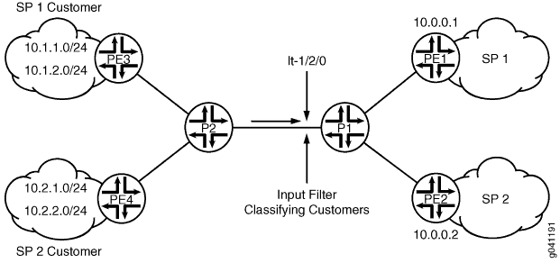
图 2 显示了此示例中使用的拓扑。
在逻辑系统 P1 上,输入过滤器对从逻辑系统 PE3 和逻辑系统 PE4 接收的数据包进行分类。这些数据包根据源地址路由。在 10.1.1.0/24 和 10.1.2.0/24 网络中具有源地址的数据包将路由到逻辑系统 PE1。在 10.2.1.0/24 和 10.2.2.0/24 网络中具有源地址的数据包将路由到逻辑系统 PE2。
 转发的逻辑系统
要建立连接,OSPF 配置在所有接口上。出于演示目的,环路接口地址在路由设备上配置为表示云中的网络。
CLI 快速配置部分显示拓扑中所有设备的整个配置。在逻辑系统 P1 上配置路由实例和在主路由器部分配置防火墙过滤器显示入口路由设备逻辑系统 P1 的逐步配置。
配置
CLI 快速配置
要快速配置此示例,请复制以下命令,将其粘贴到文本文件中,移除任何换行符,更改与网络配置匹配所需的任何详细信息,然后将命令复制粘贴到 [edit] 层次结构级别的 CLI 中。
set firewall filter classify-customers term sp1-customers from source-address 10.1.1.0/24
set firewall filter classify-customers term sp1-customers from source-address 10.1.2.0/24
set firewall filter classify-customers term sp1-customers then log
set firewall filter classify-customers term sp1-customers then logical-system P1 routing-instance sp1-route-table
set firewall filter classify-customers term sp2-customers from source-address 10.2.1.0/24
set firewall filter classify-customers term sp2-customers from source-address 10.2.2.0/24
set firewall filter classify-customers term sp2-customers then log
set firewall filter classify-customers term sp2-customers then logical-system P1 routing-instance sp2-route-table
set firewall filter classify-customers term default then accept
set logical-systems P1 interfaces lt-1/2/0 unit 10 encapsulation ethernet
set logical-systems P1 interfaces lt-1/2/0 unit 10 peer-unit 9
set logical-systems P1 interfaces lt-1/2/0 unit 10 family inet filter input classify-customers
set logical-systems P1 interfaces lt-1/2/0 unit 10 family inet address 172.16.0.10/30
set logical-systems P1 interfaces lt-1/2/0 unit 13 encapsulation ethernet
set logical-systems P1 interfaces lt-1/2/0 unit 13 peer-unit 14
set logical-systems P1 interfaces lt-1/2/0 unit 13 family inet address 172.16.0.13/30
set logical-systems P1 interfaces lt-1/2/0 unit 17 encapsulation ethernet
set logical-systems P1 interfaces lt-1/2/0 unit 17 peer-unit 18
set logical-systems P1 interfaces lt-1/2/0 unit 17 family inet address 172.16.0.17/30
set logical-systems P1 protocols ospf rib-group fbf-group
set logical-systems P1 protocols ospf area 0.0.0.0 interface all
set logical-systems P1 protocols ospf area 0.0.0.0 interface fxp0.0 disable
set logical-systems P1 routing-instances sp1-route-table instance-type forwarding
set logical-systems P1 routing-instances sp1-route-table routing-options static route 0.0.0.0/0 next-hop 172.16.0.13
set logical-systems P1 routing-instances sp2-route-table instance-type forwarding
set logical-systems P1 routing-instances sp2-route-table routing-options static route 0.0.0.0/0 next-hop 172.16.0.17
set logical-systems P1 routing-options rib-groups fbf-group import-rib inet.0
set logical-systems P1 routing-options rib-groups fbf-group import-rib sp1-route-table.inet.0
set logical-systems P1 routing-options rib-groups fbf-group import-rib sp2-route-table.inet.0
set logical-systems P2 interfaces lt-1/2/0 unit 2 encapsulation ethernet
set logical-systems P2 interfaces lt-1/2/0 unit 2 peer-unit 1
set logical-systems P2 interfaces lt-1/2/0 unit 2 family inet address 172.16.0.2/30
set logical-systems P2 interfaces lt-1/2/0 unit 6 encapsulation ethernet
set logical-systems P2 interfaces lt-1/2/0 unit 6 peer-unit 5
set logical-systems P2 interfaces lt-1/2/0 unit 6 family inet address 172.16.0.6/30
set logical-systems P2 interfaces lt-1/2/0 unit 9 encapsulation ethernet
set logical-systems P2 interfaces lt-1/2/0 unit 9 peer-unit 10
set logical-systems P2 interfaces lt-1/2/0 unit 9 family inet address 172.16.0.9/30
set logical-systems P2 protocols ospf area 0.0.0.0 interface all
set logical-systems P2 protocols ospf area 0.0.0.0 interface fxp0.0 disable
set logical-systems PE1 interfaces lt-1/2/0 unit 14 encapsulation ethernet
set logical-systems PE1 interfaces lt-1/2/0 unit 14 peer-unit 13
set logical-systems PE1 interfaces lt-1/2/0 unit 14 family inet address 172.16.0.14/30
set logical-systems PE1 interfaces lo0 unit 3 family inet address 172.16.1.1/32
set logical-systems PE1 protocols ospf area 0.0.0.0 interface all
set logical-systems PE1 protocols ospf area 0.0.0.0 interface fxp0.0 disable
set logical-systems PE2 interfaces lt-1/2/0 unit 18 encapsulation ethernet
set logical-systems PE2 interfaces lt-1/2/0 unit 18 peer-unit 17
set logical-systems PE2 interfaces lt-1/2/0 unit 18 family inet address 172.16.0.18/30
set logical-systems PE2 interfaces lo0 unit 4 family inet address 172.16.2.2/32
set logical-systems PE2 protocols ospf area 0.0.0.0 interface all
set logical-systems PE2 protocols ospf area 0.0.0.0 interface fxp0.0 disable
set logical-systems PE3 interfaces lt-1/2/0 unit 1 encapsulation ethernet
set logical-systems PE3 interfaces lt-1/2/0 unit 1 peer-unit 2
set logical-systems PE3 interfaces lt-1/2/0 unit 1 family inet address 172.16.0.1/30
set logical-systems PE3 interfaces lo0 unit 1 family inet address 10.1.1.1/32
set logical-systems PE3 interfaces lo0 unit 1 family inet address 10.1.2.1/32
set logical-systems PE3 protocols ospf area 0.0.0.0 interface all
set logical-systems PE3 protocols ospf area 0.0.0.0 interface fxp0.0 disable
set logical-systems PE4 interfaces lt-1/2/0 unit 5 encapsulation ethernet
set logical-systems PE4 interfaces lt-1/2/0 unit 5 peer-unit 6
set logical-systems PE4 interfaces lt-1/2/0 unit 5 family inet address 172.16.0.5/30
set logical-systems PE4 interfaces lo0 unit 2 family inet address 10.2.1.1/32
set logical-systems PE4 interfaces lo0 unit 2 family inet address 10.2.2.1/32
set logical-systems PE4 protocols ospf area 0.0.0.0 interface all
set logical-systems PE4 protocols ospf area 0.0.0.0 interface fxp0.0 disable
在主路由器上配置防火墙过滤器
逐步过程
以下示例要求您在配置层次结构中导航各个级别。有关导航 CLI 的信息,请参阅 CLI 用户指南中的配置模式下使用 CLI 编辑器。
要在主路由器上配置防火墙过滤器:
配置 SP1 客户的源地址。
[edit firewall filter classify-customers term sp1-customers]
user@host# set from source-address 10.1.1.0/24
user@host# set from source-address 10.1.2.0/24
配置使用指定源地址接收数据包时所采取的操作。
要跟踪防火墙过滤器的操作,将配置日志操作。逻辑系统 P1 上的 sp1 路由表.inet.0 路由表将数据包路由。
[edit firewall filter classify-customers term sp1-customers]
user@host# set then log
user@host# set then logical-system P1 routing-instance sp1-route-table
配置 SP2 客户的源地址。
[edit firewall filter classify-customers term sp2-customers]
user@host# set from source-address 10.2.1.0/24
user@host# set from source-address 10.2.2.0/24
配置使用指定源地址接收数据包时所采取的操作。
要跟踪防火墙过滤器的操作,将配置日志操作。逻辑系统 P1 上的 sp2 路由表.inet.0 路由表将数据包路由。
[edit firewall filter classify-customers term sp2-customers]
user@host# set then log
user@host# set then logical-system P1 routing-instance sp2-route-table
从任何其他源地址接收数据包时,配置要采取的操作。
所有这些数据包均仅使用默认 IPv4 单播路由表 inet.0 来接受和路由。
[edit firewall filter classify-customers term default]
user@host# set then accept
在逻辑系统 P1 上配置路由实例
逐步过程
以下示例要求您在配置层次结构中导航各个级别。有关导航 CLI 的信息,请参阅 CLI 用户指南中的配置模式下使用 CLI 编辑器。
要在逻辑系统上配置路由实例:
配置逻辑系统上的接口。
[edit logical-systems P1 interfaces lt-1/2/0]
user@host# set unit 10 encapsulation ethernet
user@host# set unit 10 peer-unit 9
user@host# set unit 10 family inet address 172.16.0.10/30
user@host# set unit 13 encapsulation ethernet
user@host# set unit 13 peer-unit 14
user@host# set unit 13 family inet address 172.16.0.13/30
user@host# set unit 17 encapsulation ethernet
user@host# set unit 17 peer-unit 18
user@host# set unit 17 family inet address 172.16.0.17/30
classify-customers将防火墙过滤器分配给路由器接口 lt-1/2/0.10 作为输入数据包过滤器。[edit logical-systems P1 interfaces lt-1/2/0] user@host# set unit 10 family inet filter input classify-customers
使用路由协议或静态路由配置连接。
作为最佳做法,禁用管理接口上的路由。
[edit  logical-systems P1 protocols ospf area 0.0.0.0]
user@host# set interface all
user@host# set interface fxp0.0 disable
创建路由实例。
防火墙过滤器中
classify-customers引用了这些路由实例。转发实例类型支持基于过滤器的转发,其中接口与实例无关。所有接口都属于默认实例,在此情况下,逻辑系统 P1。
[edit logical-systems P1 routing-instances]
user@host# set sp1-route-table instance-type forwarding
user@host# set sp2-route-table instance-type forwarding
解析路由实例中安装的路由,以直接连接下一跳跃。
[edit logical-systems P1 routing-instances]
user@host# set sp1-route-table routing-options static route 0.0.0.0/0 next-hop 172.16.0.13
user@host# set sp2-route-table routing-options static route 0.0.0.0/0 next-hop 172.16.0.17
将路由表组合在一起,形成一个路由表组。
第一个路由表 inet.0 是主路由表,而其他路由表则是辅助路由表。
在此情况下,主路由表可确定路由表组的地址族,在此情况下为 IPv4。
[edit logical-systems P1 routing-options]
user@host# set rib-groups fbf-group import-rib inet.0
user@host# set rib-groups fbf-group import-rib sp1-route-table.inet.0
user@host# set rib-groups fbf-group import-rib sp2-route-table.inet.0
将路由表组应用到 OSPF。
这会使 OSPF 路由安装到组中的所有路由表中。
[edit logical-systems P1 protocols ospf]
user@host# set rib-group fbf-group
如果完成设备配置,请提交配置。
[edit]
user@host# commit
结果
发出 show firewall 和 show logical-systems P1 命令,以确认您的配置。
user@host# show firewall
filter classify-customers {
    term sp1-customers {
        from {
            source-address {
                10.1.1.0/24;
                10.1.2.0/24;
            }
        }
        then {
            log;
            logical-system P1 routing-instance sp1-route-table;
        }
    }
    term sp2-customers {
        from {
            source-address {
                10.2.1.0/24;
                10.2.2.0/24;
            }
        }
        then {
            log;
            logical-system P1 routing-instance sp2-route-table;
        }
    }
    term default {
        then accept;
    }
}
user@host# show logical-systems P1
interfaces {
    lt-1/2/0 {
        unit 10 {
            encapsulation ethernet;
            peer-unit 9;
            family inet {
                filter {
                    input classify-customers;
                }
                address 172.16.0.10/30;
            }
        }
        unit 13 {
            encapsulation ethernet;
            peer-unit 14;
            family inet {
                address 172.16.0.13/30;
            }
        }
        unit 17 {
            encapsulation ethernet;
            peer-unit 18;
            family inet {
                address 172.16.0.17/30;
            }
        }
    }
}
protocols {
    ospf {
        rib-group fbf-group;
        area 0.0.0.0 {
            interface all;
            interface fxp0.0 {
                disable;
            }
        }
    }
}
routing-instances {
    sp1-route-table {
        instance-type forwarding;
        routing-options {
            static {
                route 0.0.0.0/0 next-hop 172.16.0.13;
            }
        }
    }
    sp2-route-table {
        instance-type forwarding;
        routing-options {
            static {
                route 0.0.0.0/0 next-hop 172.16.0.17;
            }
        }
    }
}
routing-options {
    rib-groups {
        fbf-group {
            import-rib [ inet.0 sp1-route-table.inet.0 sp2-route-table.inet.0 ];
        }
    }
}
验证
确认配置工作正常。
带指定源地址的 Pinging
目的
在整个网络中发送一些 ICMP 数据包以测试防火墙过滤器。
行动
登录逻辑系统 PE3。
user@host> set cli logical-system PE3
Logical system: PE3
ping运行 命令,在逻辑系统 PE1 上 ping lo0.3 接口。此接口上配置的地址为 172.16.1.1。
指定源地址 10.1.2.1,这是逻辑系统 PE3 上的 lo0.1 接口上配置的地址。
user@host:PE3> ping 172.16.1.1 source 10.1.2.1
PING 172.16.1.1 (172.16.1.1): 56 data bytes
64 bytes from 172.16.1.1: icmp_seq=0 ttl=62 time=1.444 ms
64 bytes from 172.16.1.1: icmp_seq=1 ttl=62 time=2.094 ms
^C
--- 172.16.1.1 ping statistics ---
2 packets transmitted, 2 packets received, 0% packet loss
round-trip min/avg/max/stddev = 1.444/1.769/2.094/0.325 ms
登录逻辑系统 PE4。
user@host:PE3> set cli logical-system PE4
Logical system: PE4
运行 命令
ping,在逻辑系统 PE2 上 ping lo0.4 接口。此接口上配置的地址为 172.16.2.2。
指定源地址 10.2.1.1,这是逻辑系统 PE4 上的 lo0.2 接口上配置的地址。
user@host:PE4> ping 172.16.2.2 source 10.2.1.1
PING 172.16.2.2 (172.16.2.2): 56 data bytes
64 bytes from 172.16.2.2: icmp_seq=0 ttl=62 time=1.473 ms
64 bytes from 172.16.2.2: icmp_seq=1 ttl=62 time=1.407 ms
^C
--- 172.16.2.2 ping statistics ---
2 packets transmitted, 2 packets received, 0% packet loss
round-trip min/avg/max/stddev = 1.407/1.440/1.473/0.033 ms
意义
发送这些 ping 激活防火墙过滤器操作。
验证防火墙过滤器
目的
确保防火墙过滤器操作生效。
行动
登录逻辑系统 P1。
user@host> set cli logical-system P1
Logical system: P1
在
show firewall log逻辑系统 P1 上运行 命令。user@host:P1> show firewall log Log : Time Filter Action Interface Protocol Src Addr Dest Addr 13:52:20 pfe A lt-1/2/0.10 ICMP 10.2.1.1 172.16.2.2 13:52:19 pfe A lt-1/2/0.10 ICMP 10.2.1.1 172.16.2.2 13:51:53 pfe A lt-1/2/0.10 ICMP 10.1.2.1 172.16.1.1 13:51:52 pfe A lt-1/2/0.10 ICMP 10.1.2.1 172.16.1.1

