租户系统流
本主题介绍如何在配置了租户系统的设备上的流会话中处理数据包。它介绍了运行租户系统的设备如何处理租户系统之间的直通流量。本主题还介绍自流量,即租户系统内的自发起流量和在另一个租户系统上终止的自流量。在解决租户系统问题之前,本主题将提供有关数据包处理和会话的安全架构的基本信息。最后,讲解会话以及如何更改会话特征。
为运行租户系统的设备创建会话
系统会根据路由和其他分类信息创建会话,用于存储信息并为流分配资源。基本上,当流量进入租户系统接口时,将建立会话,并执行路由查找以识别下一跳点接口,并执行策略查找。
或者,租户系统使您能够配置内部软件交换机。虚拟专用 LAN 交换机 (VPLS) 在租户系统中作为互连实施。VPLS 使中转流量和在租户系统终止的流量能够在租户系统之间传递。为了允许流量在租户系统之间或租户系统与逻辑系统之间传递,使用了跨互连租户系统的逻辑隧道 (lt-0/0/0) 接口。
数据包序列发生在入口接口和出口接口。在租户系统之间遍历的数据包可能无法按照物理接口上接收的顺序进行处理。
了解数据包分类
基于流的处理的数据包分类基于物理接口和 逻辑接口 ,并取决于传入接口。数据包分类在入口点执行,在流中,基于数据包的处理有时也会在 SPU 上进行。
对于配置有或没有租户系统的设备,评估数据包分类的方式相同。专用接口的流量被分类到包含该接口的租户系统。过滤器和服务等级功能通常与接口相关联,以影响允许哪些数据包通过设备,并根据需要对数据包应用特殊操作。
对于有或没有租户系统的设备,数据包分类相似,但租户系统中的监管器有其局限性。租户系统内的监管器可能无法正确注册命中。要监控命中,请将监管器应用于根系统接口。此问题仅影响监管器命中计数器,不会影响其他过滤器或服务等级功能。
了解 VPLS 交换机和逻辑隧道接口
本主题介绍互连租户系统,该系统充当内部虚拟专用 LAN 服务 (VPLS) 交换机,用于将设备上的一个租户系统连接到另一个租户系统。本主题还说明如何使用逻辑隧道 (lt-0/0/0) 接口通过互连租户系统连接租户系统。
运行租户系统的设备可以使用内部 VPLS 交换机传递流量,而无需流量离开设备。要在设备上的租户系统之间进行通信,您必须在将使用内部交换机的每个租户系统上配置一个 lt-0/0/0 接口,并且必须将其与互连租户系统上的对等方 lt-0/0/0 接口相关联,从而有效地在它们之间创建逻辑隧道。配置租户系统的 lt-0/0/0 接口时,可以在隧道的每一端定义对等关系。
您可能希望设备上的所有租户系统能够相互通信,而无需使用外部交换机。或者,您可能希望某些租户系统通过内部交换机进行连接,但不是全部系统。
如果在任何租户系统中配置 lt-0/0/0 接口,并且未配置包含对等方 lt-0/0/0 接口的 VPLS 交换机,则提交将失败。
运行租户系统的安全设备可在 机箱群集 中使用,并且每个节点具有相同的配置。
使用机箱群集内配置了租户系统的安全设备时,必须为机箱群集中的每个节点购买并安装相同数量的许可证。租户系统许可证与机箱群集内的单个机箱或节点相关,而不是该群集的全部内容。
处理租户系统的直通流量
对于运行租户系统的安全设备,直通流量可以存在于租户系统内部或租户系统之间。
租户系统之间的直通流量
租户系统之间的直通流量很复杂,因为每个租户系统都有一个流量必须通过的入口和出口接口。就好像流量从两台设备进出一样。考虑如何在 图 1 所示拓扑中给出的租户系统之间处理直通流量。
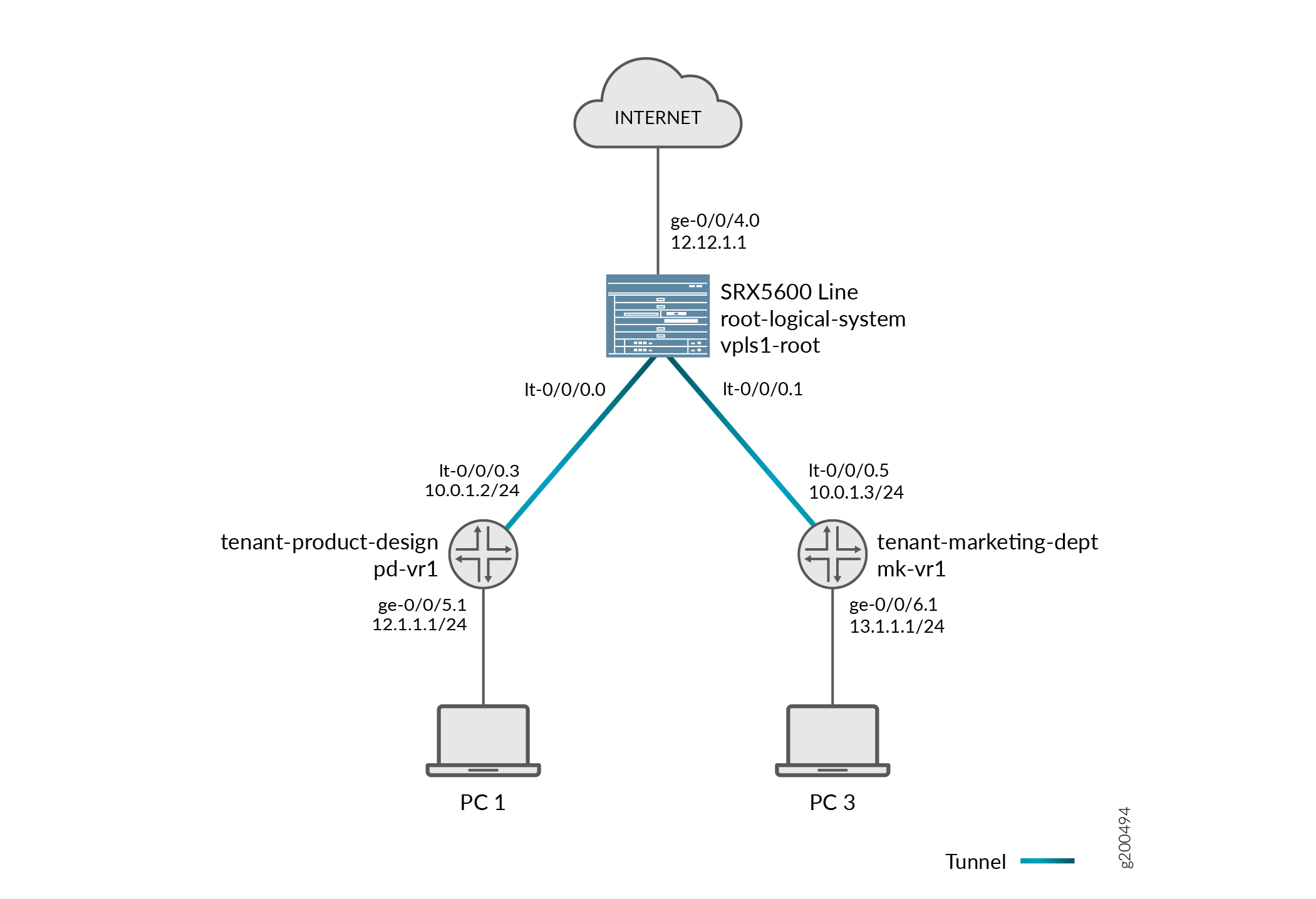
必须为租户系统之间的直通流量建立两个会话。(请注意,策略查找是在两个租户系统中执行的)。
-
在传入租户系统上,入口接口(物理接口)与其出口接口(lt-0/0/0 接口)之间会建立一个会话。
-
在出口租户系统上,入口接口(第二个租户系统的 lt-0/0/0 接口)与其出口接口(物理接口)之间会建立另一个会话。
考虑如何在 图 1 所示的拓扑中跨租户系统处理直通流量。
-
在传入租户系统中建立会话。
-
当数据包到达接口 ge-0/0/5 时,会将其识别为属于租户产品设计租户系统。
-
由于 ge-0/0/5 属于 pd-vr1 路由实例,因此路由查找在 pd-vr1 中执行。
-
查找结果是,数据包的出口接口标识为 lt-0/0/0.3,下一跃点标识为 lt-0/0/0.5,即租户营销部门中的入口接口。
-
在 ge-0/0/5 和 lt-0/0/0.3 之间建立会话。
-
-
将在传出租户系统中建立会话。
-
数据包从 lt-0/0/0.5 再次注入到流中,标识为 tenant-marketing-dept 的租户系统上下文从接口派生。
-
租户-营销-部门租户系统中继续进行数据包处理。
-
为了识别出口接口,可以在 mk-vr1 路由实例中执行数据包的路由查找。
-
传出接口标识为 ge-0/0/6,数据包从接口传输到网络。
-
处理自我流量
自流量是指源自设备上的租户系统,然后从该租户系统发送到网络,或在设备上的其他租户系统上终止的流量。
自发起流量
自发起流量从源租户系统上下文生成,然后从租户系统接口直接转发到网络。
将发生以下过程:
-
在租户系统中生成数据包时,租户系统中将启动处理流量的流程。
-
将执行路由查找以识别出口接口,并建立会话。
-
租户系统会执行策略查找并相应地处理流量。
在 给定图 1 所示的拓扑结构下,考虑如何跨租户系统处理自发起的流量。
-
在租户-产品-设计租户系统中生成一个数据包,并在租户系统中启动处理流量的流程。
-
路由查找在 pd-vr2 中执行,出口接口标识为 ge-0/0/8。
-
会话已建立。
-
数据包从 ge-0/0/8 传输到网络。
在租户系统上终止的流量
当数据包通过属于租户系统的接口进入设备,且数据包发往设备上的其他租户系统时,数据包将在租户系统之间转发,其转发方式与直通流量相同。但是,第二个租户系统中的路由查找会将本地出口接口识别为数据包目标。因此,数据包在第二个租户系统上作为自流量终止。
-
对于已终止的自流量,将执行两次策略查找并建立两个会话。
-
在传入租户系统上,入口接口(物理接口)与其出口接口(lt-0/0/0 接口)之间会建立一个会话。
-
在目标租户系统上,入口接口(第二个租户系统的 lt-0/0/0 接口)与本地接口之间会建立另一个会话。
-
考虑如何在 图 1 所示的拓扑结构中跨租户系统处理已终止的自流量。
-
在传入租户系统中建立会话。
-
当数据包到达接口 ge-0/0/5 时,会将其识别为属于租户产品设计租户系统。
-
由于 ge-0/0/5 属于 pd-vr1 路由实例,因此路由查找在 pd-vr1 中执行。
-
查找结果是,数据包的出口接口标识为 lt-0/0/0.3,下一跃点标识为 lt-0/0/0.5,即 ls-marketing-dept 中的入口接口。
-
在 ge-0/0/5 和 lt-0/0/0.3 之间建立会话。
-
-
管理会话将在目标租户系统中建立。
-
数据包从 lt-0/0/0.5 再次注入到流中,标识为 tenant-marketing-dept 的租户系统上下文从接口派生。
-
租户-营销-部门租户系统中继续进行数据包处理。
-
数据包的路由查找在 mk-vr1 路由实例中执行。数据包在目标租户系统中以自流量的形式终止。
-
了解会话和门限控制
系统会根据路由和其他分类信息创建会话,以存储信息并为流量分配资源。租户系统流模块提供会话和门限制,以确保在租户系统之间共享这些资源。每个租户系统的资源分配和限制在绑定到租户系统的安全配置文件中指定。
-
对于会话限制,系统根据为租户系统配置的最大会话数检查会话的第一个数据包。当达到会话的最大限制时,设备将丢弃数据包并记录事件。
-
对于门限,设备根据为租户系统配置的最大门数检查会话的第一个数据包。如果达到租户系统的最大门数,设备将拒绝门打开请求并记录事件。
关于配置会话
根据协议和服务,会话会使用超时值进行编程。例如,TCP 的默认超时为 1800 秒。UDP 的默认超时为 60 秒。当流量终止时,该流量将被标记为无效,并且其超时时间减少为 10 秒。如果没有流量在服务超时之前使用会话,则会话将老化并释放到公共资源池中以供重复使用。
您可以通过以下方式影响会话的生存期:
-
根据会话表的满度对会话进行老化。
-
设置过期 TCP 会话的显式超时。
-
将 TCP 会话配置为在收到 TCP RST(重置)消息时失效。
-
您可以按如下方式配置会话以容纳其他系统:
-
禁用 TCP 数据包安全检查。
-
更改最大区段大小。
-
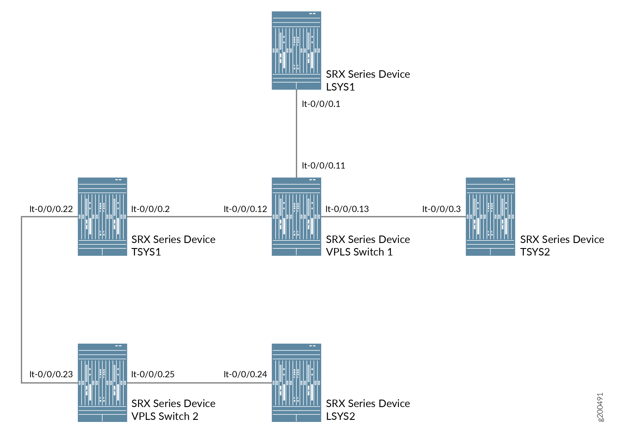
配置逻辑系统和租户系统 与多个 VPLS 交换机互连
此示例说明如何使用多个 VPLS 交换机互连逻辑系统和租户系统。实现方式是将多个逻辑系统和租户系统配置在一个租户系统下具有多个逻辑隧道 (LT) 接口,以及配置为在不离开安全设备的情况下传递流量的多个 VPLS 交换机。
要求
此示例使用运行 Junos OS 以及逻辑系统和租户系统的安全设备。
概述
在此示例中,我们将在一个租户系统下配置多个 LT 接口和多个 VPLS 交换机。
在此示例中,我们还使用 LT 接口点对点连接(封装以太网和封装帧中继)配置多个逻辑系统和租户系统之间的互连。
对于具有多台 VPLS 交换机的互连逻辑系统和租户系统,此示例将逻辑隧道接口 lt-0/0/0 配置为 ethernet-vpls 作为封装类型。相应的对等方 lt-0/0/0 接口和安全配置文件会分配给逻辑系统和租户系统。VPLS 交换机 1 和 VPLS 交换机 2 的路由实例也会分配给逻辑系统和租户系统。
图 2 显示了具有多个 VPLS 交换机的互连逻辑系统和租户系统的拓扑。
配置
要为逻辑系统和租户系统配置接口,请执行以下操作:
CLI 快速配置
要快速配置此示例,请复制以下命令,将其粘贴到文本文件中,删除所有换行符,更改详细信息,以便与网络配置匹配,将命令复制并粘贴到层次结构级别的 [edit] CLI 中,然后从配置模式进入。commit
set interfaces lt-0/0/0 unit 11 encapsulation ethernet-vpls
set interfaces lt-0/0/0 unit 11 peer-unit 1
set interfaces lt-0/0/0 unit 12 encapsulation ethernet-vpls
set interfaces lt-0/0/0 unit 12 peer-unit 2
set interfaces lt-0/0/0 unit 13 encapsulation ethernet-vpls
set interfaces lt-0/0/0 unit 13 peer-unit 3
set interfaces lt-0/0/0 unit 23 encapsulation ethernet-vpls
set interfaces lt-0/0/0 unit 23 peer-unit 22
set interfaces lt-0/0/0 unit 25 encapsulation ethernet-vpls
set interfaces lt-0/0/0 unit 25 peer-unit 24
set routing-instances vpls-switch-1 instance-type vpls
set routing-instances vpls-switch-1 interface lt-0/0/0.11
set routing-instances vpls-switch-1 interface lt-0/0/0.12
set routing-instances vpls-switch-1 interface lt-0/0/0.13
set routing-instances vpls-switch-2 instance-type vpls
set routing-instances vpls-switch-2 interface lt-0/0/0.23
set routing-instances vpls-switch-2 interface lt-0/0/0.25
set logical-systems LSYS1 interfaces lt-0/0/0 unit 1 encapsulation ethernet
set logical-systems LSYS1 interfaces lt-0/0/0 unit 1 peer-unit 11
set logical-systems LSYS1 interfaces lt-0/0/0 unit 1 family inet address 192.168.0.1/24
set interfaces lt-0/0/0 unit 2 encapsulation ethernet
set interfaces lt-0/0/0 unit 2 peer-unit 12
set interfaces lt-0/0/0 unit 2 family inet address 192.168.0.2/24
set interfaces lt-0/0/0 unit 22 encapsulation ethernet
set interfaces lt-0/0/0 unit 22 peer-unit 23
set interfaces lt-0/0/0 unit 22 family inet address 192.168.4.1/30
set tenants TSYS1 routing-instances vr11 instance-type virtual-router
set tenants TSYS1 routing-instances vr11 interface lt-0/0/0.2
set tenants TSYS1 routing-instances vr11 interface lt-0/0/0.22
set interfaces lt-0/0/0 unit 3 encapsulation ethernet
set interfaces lt-0/0/0 unit 3 peer-unit 13
set interfaces lt-0/0/0 unit 3 family inet address 192.168.0.3/24
set tenants TSYS2 routing-instances vr12 instance-type virtual-router
set tenants TSYS2 routing-instances vr12 interface lt-0/0/0.3
set logical-systems LSYS2 interfaces lt-0/0/0 unit 24 encapsulation ethernet
set logical-systems LSYS2 interfaces lt-0/0/0 unit 24 peer-unit 25
set logical-systems LSYS2 interfaces lt-0/0/0 unit 24 family inet address 192.168.4.2/30
set system security-profile SP-user policy maximum 100
set system security-profile SP-user policy reserved 50
set system security-profile SP-user zone maximum 60
set system security-profile SP-user zone reserved 10
set system security-profile SP-user flow-session maximum 100
set system security-profile SP-user flow-session reserved 50
set system security-profile SP-user logical-system LSYS1
set system security-profile SP-user tenant TSYS1
set system security-profile SP-user tenant TSYS2
set system security-profile SP-user logical-system LSYS2
过程
分步程序
下面的示例要求您在各个配置层级中进行导航。有关操作说明,请参阅在 配置模式下使用 CLI 编辑器。
-
配置 lt-0/0/0 接口。
[edit]
user@host# set interfaces lt-0/0/0 unit 11 encapsulation ethernet-vpls
user@host# set interfaces lt-0/0/0 unit 11 peer-unit 1
user@host# set interfaces lt-0/0/0 unit 12 encapsulation ethernet-vpls
user@host# set interfaces lt-0/0/0 unit 12 peer-unit 2
user@host# set interfaces lt-0/0/0 unit 13 encapsulation ethernet-vpls
user@host# set interfaces lt-0/0/0 unit 13 peer-unit 3
user@host# set interfaces lt-0/0/0 unit 23 encapsulation ethernet-vpls
user@host# set interfaces lt-0/0/0 unit 23 peer-unit 22
user@host# set interfaces lt-0/0/0 unit 25 encapsulation ethernet-vpls
user@host# set interfaces lt-0/0/0 unit 25 peer-unit 24
-
为 VPLS 交换机配置路由实例,并为其添加接口。
[edit]
user@host# set routing-instances vpls-switch-1 instance-type vpls
user@host# set routing-instances vpls-switch-1 interface lt-0/0/0.11
user@host# set routing-instances vpls-switch-1 interface lt-0/0/0.12
user@host# set routing-instances vpls-switch-1 interface lt-0/0/0.13
user@host# set routing-instances vpls-switch-2 instance-type vpls
user@host# set routing-instances vpls-switch-2 interface lt-0/0/0.23
user@host# set routing-instances vpls-switch-2 interface lt-0/0/0.25
-
使用 lt-0/0/0.1 接口和对等方 lt-0/0/0.11 配置 LSYS1。
[edit]
user@host# set logical-systems LSYS1 interfaces lt-0/0/0 unit 1 encapsulation ethernet
user@host# set logical-systems LSYS1 interfaces lt-0/0/0 unit 1 peer-unit 11
user@host# set logical-systems LSYS1 interfaces lt-0/0/0 unit 1 family inet address 192.168.0.1/24
-
使用 lt-0/0/0.2 接口和对等方 lt-0/0/0.12 配置 TSYS1。
[edit]
user@host# set interfaces lt-0/0/0 unit 2 encapsulation ethernet
user@host# set interfaces lt-0/0/0 unit 2 peer-unit 12
user@host# set interfaces lt-0/0/0 unit 2 family inet address 192.168.0.2/24
user@host# set interfaces lt-0/0/0 unit 22 encapsulation ethernet
user@host# set interfaces lt-0/0/0 unit 22 peer-unit 23
user@host# set interfaces lt-0/0/0 unit 22 family inet address 192.168.4.1/30
user@host# set tenants TSYS1 routing-instances vr11 instance-type virtual-router
user@host# set tenants TSYS1 routing-instances vr11 interface lt-0/0/0.2
user@host# set tenants TSYS1 routing-instances vr11 interface lt-0/0/0.22
-
使用 lt-0/0/0.3 接口和对等方 lt-0/0/0.13 配置 TSYS2
[edit]
user@host# set interfaces lt-0/0/0 unit 3 encapsulation ethernet
user@host# set interfaces lt-0/0/0 unit 3 peer-unit 13
user@host# set interfaces lt-0/0/0 unit 3 family inet address 192.168.0.3/24
user@host# set tenants TSYS2 routing-instances vr12 instance-type virtual-router
user@host# set tenants TSYS2 routing-instances vr12 interface lt-0/0/0.3
-
使用 lt-0/0/0 接口和对等单元 24 配置 LSYS2。
[edit]
user@host# set logical-systems LSYS2 interfaces lt-0/0/0 unit 24 encapsulation ethernet
user@host# set logical-systems LSYS2 interfaces lt-0/0/0 unit 24 peer-unit 25
user@host# set logical-systems LSYS2 interfaces lt-0/0/0 unit 24 family inet address 192.168.4.2/30
-
为逻辑系统分配安全配置文件。
[edit]
user@host# set system security-profile SP-user policy maximum 100
user@host# set system security-profile SP-user policy reserved 50
user@host# set system security-profile SP-user zone maximum 60
user@host# set system security-profile SP-user zone reserved 10
user@host# set system security-profile SP-user flow-session maximum 100
user@host#set system security-profile SP-user flow-session reserved 50
user@host# set system security-profile SP-user logical-system LSYS1
user@host# set system security-profile SP-user tenant TSYS1
user@host# set system security-profile SP-user tenant TSYS2
user@host# set system security-profile SP-user logical-system LSYS2
结果
-
在配置模式下,输入
show interfaces lt-0/0/0,命令以确认您的配置。如果输出未显示预期的配置,请重复此示例中的配置说明进行更正unit 2 { encapsulation ethernet; peer-unit 12; family inet { address 192.168.0.2/24; } } unit 3 { encapsulation ethernet; peer-unit 13; family inet { address 192.168.0.3/24; } } unit 11 { encapsulation ethernet-vpls; peer-unit 1; } unit 12 { encapsulation ethernet-vpls; peer-unit 2; } unit 13 { encapsulation ethernet-vpls; peer-unit 3; } unit 22 { encapsulation ethernet; peer-unit 23; family inet { address 192.168.4.1/30; } } unit 23 { encapsulation ethernet-vpls; peer-unit 22; } unit 25 { encapsulation ethernet-vpls; peer-unit 24; } -
在配置模式下,输入
show routing-instances,命令以确认您的配置。如果输出未显示预期的配置,请重复此示例中的配置说明进行更正。[edit] user@host# show routing-instances vpls-switch-1 { instance-type vpls; interface lt-0/0/0.11; interface lt-0/0/0.12; interface lt-0/0/0.13; } vpls-switch-2 { instance-type vpls; interface lt-0/0/0.23; interface lt-0/0/0.25; } -
在配置模式下,输入
show logical-systems LSYS1,命令以确认您的配置。如果输出未显示预期的配置,请重复此示例中的配置说明进行更正。[edit] user@host# show logical-systems LSYS1 interfaces { lt-0/0/0 { unit 1 { encapsulation ethernet; peer-unit 11; family inet { address 192.168.0.1/24; } } } } -
在配置模式下,输入
show logical-systems LSYS2,命令以确认您的配置。如果输出未显示预期的配置,请重复此示例中的配置说明进行更正。[edit] user@host# show tenants TSYS1 routing-instances { vr11 { instance-type virtual-router; interface lt-0/0/0.2; interface lt-0/0/0.22; } } -
在配置模式下,输入
show logical-systems LSYS3,命令以确认您的配置。如果输出未显示预期的配置,请重复此示例中的配置说明进行更正。[edit] user@host# show tenants TSYS2 routing-instances { vr12 { instance-type virtual-router; interface lt-0/0/0.3; } } -
在配置模式下,输入
show logical-systems LSYS2,命令以确认您的配置。如果输出未显示预期的配置,请重复此示例中的配置说明进行更正。[edit] user@host# show logical-systems LSYS2 interfaces { lt-0/0/0 { unit 24 { encapsulation ethernet; peer-unit 25; family inet { address 192.168.4.2/30; } } } } -
在配置模式下,输入
show system security-profile,命令以确认您的配置。如果输出未显示预期的配置,请重复此示例中的配置说明进行更正。[edit] user@host# show system security-profile SP-user { policy { maximum 100; reserved 50; } zone { maximum 60; reserved 10; } flow-session { maximum 100; reserved 50; } logical-system [ LSYS1 LSYS2 ]; tenant [ TSYS1 TSYS2 ]; }
如果完成设备配置,请从配置模式进入。commit
验证
要确认配置工作正常,请执行以下任务:
验证逻辑系统的安全性配置文件
目的
验证每个逻辑系统的安全配置文件。
行动
在操作模式下,输入命令 show system security-profile security-log-stream-number logical-system all 。
user@host> show system security-profile assignment summary
                                    Total     Maximum
security-profiles                       1          65
logical-systems                         1          32
tenants                                 0          32
logical-systems and tenants             1          64
意义
配置 security-log-stream 时,输出提供逻辑系统的使用情况和保留值。
验证逻辑系统的 LT 接口
目的
验证逻辑系统的接口。
行动
在操作模式下,输入命令 show interfaces lt-0/0/0 terse 。
user@host> show interfaces lt-0/0/0 terse
Interface               Admin Link Proto    Local                 Remote
lt-0/0/0                up    up
lt-0/0/0.1              up    up   inet     192.168.0.1/24
lt-0/0/0.2              up    up   inet     192.168.0.2/24
lt-0/0/0.3              up    up   inet     192.168.0.3/24
lt-0/0/0.11             up    up   vpls
lt-0/0/0.12             up    up   vpls
lt-0/0/0.13             up    up   vpls
lt-0/0/0.22             up    up   inet     192.168.4.1/30
lt-0/0/0.23             up    up   vpls
lt-0/0/0.24             up    up   inet     192.168.4.2/30
lt-0/0/0.25             up    up   vpls
lt-0/0/0.32767          up    up
意义
输出提供 LT 接口的状态。所有 LT 接口均已开启。
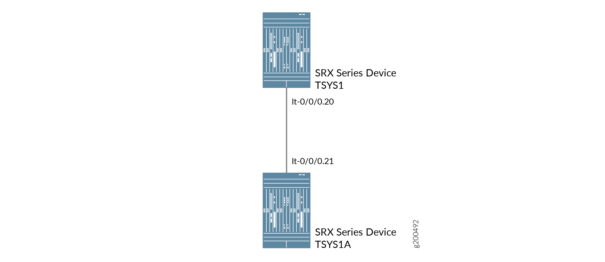
配置租户系统 使用逻辑隧道接口互连 点对点连接
此示例说明如何在点对点连接中将租户系统与逻辑隧道 (LT) 接口互连。
要求
此示例使用运行 Junos OS 以及逻辑系统和租户系统的安全设备。
概述
在此示例中,我们将展示如何在点对点连接中将租户系统与逻辑隧道 (LT) 接口互连。
对于具有点对点连接(封装帧中继)LT 接口的互连租户系统,此示例配置逻辑隧道接口 lt-0/0/0。此示例配置安全区域并为逻辑系统分配接口。
互连逻辑系统 lt-0/0/0 接口配置为帧中继作为封装类型。租户系统中对应的对等方 lt-0/0/0 接口配置了帧中继作为封装类型。安全配置文件将分配给租户系统。
图 3 显示了具有点对点连接 LT 接口的互连租户系统的拓扑。
 配置互连租户系统
配置
要配置安全区域并为租户系统分配接口,请执行以下操作:
CLI 快速配置
要快速配置此示例,请复制以下命令,将其粘贴到文本文件中,删除所有换行符,更改详细信息,以便与网络配置匹配,将命令复制并粘贴到层次结构级别的 [edit] CLI 中,然后从配置模式进入。commit
set system security-profile sp1 tenant TSYS1
set system security-profile sp2 tenant TSYS1A
set interfaces xe-0/0/5 gigether-options redundant-parent reth0
set interfaces xe-0/0/6 gigether-options redundant-parent reth1
set interfaces xe-1/0/5 gigether-options redundant-parent reth0
set interfaces xe-1/0/6 gigether-options redundant-parent reth1
set interfaces reth0 redundant-ether-options redundancy-group 2
set interfaces reth1 redundant-ether-options redundancy-group 1
set interfaces lt-0/0/0 unit 20 encapsulation ethernet
set interfaces lt-0/0/0 unit 20 peer-unit 21
set interfaces lt-0/0/0 unit 20 family inet address 198.51.1.20/24
set interfaces reth0 unit 0 family inet address 198.51.100.1/24
set interfaces lt-0/0/0 unit 21 encapsulation ethernet
set interfaces lt-0/0/0 unit 21 peer-unit 20
set interfaces lt-0/0/0 unit 21 family inet address 198.51.1.21/24
set interfaces reth1 unit 0 family inet address 192.0.2.1/24
set tenants TSYS1 routing-instances vr11 instance-type virtual-router
set tenants TSYS1 routing-instances vr11 interface lt-0/0/0.20
set tenants TSYS1 routing-instances vr11 interface reth0.0
set tenants TSYS1 routing-instances vr11 routing-options static route 192.0.2.0/24 next-hop 198.51.1.21
set tenants TSYS1 security policies default-policy permit-all
set tenants TSYS1 security zones security-zone trust host-inbound-traffic system-services all
set tenants TSYS1 security zones security-zone trust host-inbound-traffic protocols all
set tenants TSYS1 security zones security-zone trust interfaces reth0.0
set tenants TSYS1 security zones security-zone untrust host-inbound-traffic system-services all
set tenants TSYS1 security zones security-zone untrust host-inbound-traffic protocols all
set tenants TSYS1 security zones security-zone untrust interfaces lt-0/0/0.20
set tenants TSYS1A routing-instances vr12 instance-type virtual-router
set tenants TSYS1A routing-instances vr12 interface lt-0/0/0.21
set tenants TSYS1A routing-instances vr12 interface reth1.0
set tenants TSYS1A routing-instances vr12 routing-options static route 198.51.100.0/24 next-hop 198.51.1.20
set tenants TSYS1A security policies default-policy permit-all
set tenants TSYS1A security zones security-zone trust host-inbound-traffic system-services all
set tenants TSYS1A security zones security-zone trust host-inbound-traffic protocols all
set tenants TSYS1A security zones security-zone trust interfaces reth1.0
set tenants TSYS1A security zones security-zone untrust host-inbound-traffic system-services all
set tenants TSYS1A security zones security-zone untrust host-inbound-traffic protocols all
set tenants TSYS1A security zones security-zone untrust interfaces lt-0/0/0.21
配置 [item]
分步程序
下面的示例要求您在各个配置层级中进行导航。有关操作说明,请参阅在 配置模式下使用 CLI 编辑器。
-
定义安全配置文件 sp1 并将其分配给租户系统 TNI。定义另一个安全配置文件 sp1 并分配给租户系统 TSYS1A
[edit]
user@host# set system security-profile sp1 tenant TSYS1
user@host# set system security-profile sp2 tenant TSYS1A
-
设置 reth0 和 reth1 的接口,并将其分配给冗余组 1 和冗余组 2。
[edit]
set interfaces xe-0/0/5 gigether-options redundant-parent reth0
set interfaces xe-0/0/6 gigether-options redundant-parent reth1
set interfaces xe-1/0/5 gigether-options redundant-parent reth0
set interfaces xe-1/0/6 gigether-options redundant-parent reth1
set interfaces reth0 redundant-ether-options redundancy-group 2
set interfaces reth1 redundant-ether-options redundancy-group 1
-
将 LT 接口设置为租户系统 TSYS1 中的封装以太网。
[edit]
user@host# set interfaces lt-0/0/0 unit 20 encapsulation ethernet
-
在 LT 接口之间配置对等单元关系,从而创建点对点连接。
[edit]
user@host# set interfaces lt-0/0/0 unit 20 peer-unit 21
-
指定 LT 接口的 IP 地址。
[edit]
user@host# set interfaces lt-0/0/0 unit 20 family inet address 198.51.1.20/24
-
指定 reth0 的 IP 地址。
[edit]
user@host# set interfaces reth0 unit 0 family inet address 198.51.100.1/24
-
在租户系统 TSYS1A 中将 LT 接口设置为封装以太网。
[edit]
user@host# set interfaces lt-0/0/0 unit 21 encapsulation ethernet
-
在 LT 接口之间配置对等单元关系,从而创建点对点连接。
[edit]
user@host# set interfaces lt-0/0/0 unit 21 peer-unit 20
-
指定 LT 接口的 IP 地址。
[edit]
user@host# set interfaces lt-0/0/0 unit 21 family inet address 198.51.1.21/24
-
指定 reth1 的 IP 地址。
[edit]
user@host# set interfaces reth1 unit 0 family inet address 192.0.2.1/24
-
定义 TSYS1 的路由实例。
[edit]
set tenants TSYS1 routing-instances vr11 instance-type virtual-router
set tenants TSYS1 routing-instances vr11 interface lt-0/0/0.20
set tenants TSYS1 routing-instances vr11 interface reth0.0
set tenants TSYS1 routing-instances vr11 routing-options static route 192.0.2.0/24 next-hop 198.51.1.21
-
配置允许所有流量的安全策略。
[edit]
user@host# set tenants TSYS1 security policies default-policy permit-all
-
配置安全区域。
[edit]
set tenants TSYS1 security zones security-zone trust host-inbound-traffic system-services all
set tenants TSYS1 security zones security-zone trust host-inbound-traffic protocols all
set tenants TSYS1 security zones security-zone trust interfaces reth0.0
set tenants TSYS1 security zones security-zone untrust host-inbound-traffic system-services all
set tenants TSYS1 security zones security-zone untrust host-inbound-traffic protocols all
set tenants TSYS1 security zones security-zone untrust interfaces lt-0/0/0.20
-
定义 TSYS1A 的路由实例。
[edit]
set tenants TSYS1A routing-instances vr12 instance-type virtual-router
set tenants TSYS1A routing-instances vr12 interface lt-0/0/0.21
set tenants TSYS1A routing-instances vr12 interface reth1.0
set tenants TSYS1A routing-instances vr12 routing-options static route 198.51.100.0/24 next-hop 198.51.1.20
-
配置允许所有流量的安全策略。
[edit]
set tenants TSYS1A security policies default-policy permit-all
-
配置安全区域。
[edit]
set tenants TSYS1A security zones security-zone trust host-inbound-traffic system-services all
set tenants TSYS1A security zones security-zone trust host-inbound-traffic protocols all
set tenants TSYS1A security zones security-zone trust interfaces reth1.0
set tenants TSYS1A security zones security-zone untrust host-inbound-traffic system-services all
set tenants TSYS1A security zones security-zone untrust host-inbound-traffic protocols all
set tenants TSYS1A security zones security-zone untrust interfaces lt-0/0/0.21
结果
-
在配置模式下,输入
show tenants TSYS1命令以确认您的配置。如果输出未显示预期的配置,请重复此示例中的配置说明进行更正。[edit] user@host# show tenants TSYS1 routing-instances { vr11 { instance-type virtual-router; interface lt-0/0/0.20; interface reth0.0; routing-options { static { route 192.0.2.0/24 next-hop 198.51.1.21; } } } } security { policies { default-policy { permit-all; } } zones { security-zone trust { host-inbound-traffic { system-services { all; } protocols { all; } } interfaces { reth0.0; } } security-zone untrust { host-inbound-traffic { system-services { all; } protocols { all; } } interfaces { lt-0/0/0.20; } } } }
-
在配置模式下,输入
show tenants TSYS1A命令以确认您的配置。如果输出未显示预期的配置,请重复此示例中的配置说明进行更正。[edit] user@host# show tenants TSYS1A routing-instances { vr12 { instance-type virtual-router; interface lt-0/0/0.21; interface reth1.0; routing-options { static { route 198.51.100.0/24 next-hop 198.51.1.20; } } } } security { policies { default-policy { permit-all; } } zones { security-zone trust { host-inbound-traffic { system-services { all; } protocols { all; } } interfaces { reth1.0; } } security-zone untrust { host-inbound-traffic { system-services { all; } protocols { all; } } interfaces { lt-0/0/0.21; } } } }
如果完成设备配置,请从配置模式进入。commit
验证
要确认配置工作正常,请执行以下任务:
验证所有租户系统的安全性配置文件
目的
验证每个逻辑系统的安全配置文件。
行动
在操作模式下,输入命令 show system security-profile zone tenant al 。
user@host> show system security-profile zone tenant al
logical-system tenant name   security profile name       usage    reserved     maximum

T1                          bronze                          1           0        2048
T1A                           pX                              0           0        2048
意义
配置 security-log-stream 时,输出提供逻辑系统的使用情况和保留值。
使用逻辑隧道接口配置逻辑系统和租户系统互连 点对点连接
此示例说明如何在点对点连接中将逻辑系统和租户系统与逻辑隧道 (LT) 接口互连。
要求
此示例使用运行 Junos OS 以及逻辑系统和租户系统的安全设备。
概述
在此示例中,我们将展示如何使用逻辑隧道 (LT) 接口点对点连接将逻辑系统和租户系统互连。
对于具有点对点连接 LT 接口的互连逻辑系统和租户系统,此示例配置逻辑隧道接口 LT-0/0/0。此示例配置安全区域并为逻辑系统分配接口
为了实现逻辑系统和租户系统的互连,lt-0/0/0 接口配置了以太网作为封装类型。相应的对等方 lt-0/0/0 接口配置了以太网作为封装类型。系统会将安全配置文件分配给逻辑系统和租户系统
图 4 显示了使用 LT 接口点对点连接的互连逻辑系统和租户系统的拓扑。

配置
要配置安全区域并为逻辑系统分配接口,请执行以下操作:
CLI 快速配置
要快速配置此示例,请复制以下命令,将其粘贴到文本文件中,删除所有换行符,更改详细信息,以便与网络配置匹配,将命令复制并粘贴到层次结构级别的 [edit] CLI 中,然后从配置模式进入。commit
set system security-profile SP-user tenant TSYS2
set interfaces lt-0/0/0 unit 30 encapsulation ethernet
set interfaces lt-0/0/0 unit 30 peer-unit 31
set interfaces lt-0/0/0 unit 30 family inet address 192.255.2.1/30
set tenants TSYS2 routing-instances vr11 instance-type virtual-router
set tenants TSYS2 routing-instances vr11 interface lt-0/0/0.30
set security zones security-zone LT interfaces lt-0/0/0.30
set system security-profile SP-user logical-system LSYS3A
set logical-systems LSYS3A interfaces lt-0/0/0 unit 21 encapsulation ethernet
set logical-systems LSYS3A interfaces lt-0/0/0 unit 21 peer-unit 20
set logical-systems LSYS3A interfaces lt-0/0/0 unit 21 family inet address 192.255.2.2/30
set logical-systems LSYS3A security policies from-zone LT to-zone LT policy LT match source-address any
set logical-systems LSYS3A security policies from-zone LT to-zone LT policy LT match destination-address any
set logical-systems LSYS3A security policies from-zone LT to-zone LT policy LT match application any
set logical-systems LSYS3A security policies from-zone LT to-zone LT policy LT then permit
set logical-systems LSYS3A security policies default-policy permit-all
set logical-systems LSYS3A security zones security-zone LT host-inbound-traffic system-services all
set logical-systems LSYS3A security zones security-zone LT host-inbound-traffic protocols all
set logical-systems LSYS3A security zones security-zone LT interfaces lt-0/0/0.31
过程
分步程序
下面的示例要求您在各个配置层级中进行导航。有关操作说明,请参阅《Junos OS CLI 用户指南》中的在 配置模式下使用CLI编辑器 。
-
定义安全配置文件并分配给租户系统。
[edit]
user@host# set system security-profile SP-user tenant TSYS2
-
将 LT 接口设置为租户系统中的封装以太网。
[edit]
user@host# set interfaces lt-0/0/0 unit 20 encapsulation ethernet
-
为租户系统 TSYS2 配置对等关系。
[edit]
user@host# set interfaces lt-0/0/0 unit 20 peer-unit 21
-
指定 LT 接口的 IP 地址。
[edit]
user@host# set interfaces lt-0/0/0 unit 20 family inet address 192.255.2.1/30
-
为 LT 接口设置安全区域。
[edit]
user@host# set logical-systems LSYS2 security zones security-zone LT interfaces lt-0/0/0.30
-
定义安全配置文件并分配给逻辑系统。
[edit]
user@host# set system security-profile SP-user logical-system LSYS3A
-
定义 TSYS2 的路由实例。
[edit]
set tenants TSYS2 routing-instances vr11 instance-type virtual-router
set tenants TSYS2 routing-instances vr11 interface lt-0/0/0.30
-
在逻辑系统 3A 中将 LT 接口设置为封装以太网。
[edit]
user@host# set logical-systems LSYS3A interfaces lt-0/0/0 unit 21 encapsulation ethernet
-
为逻辑系统 LSYS3A 配置对等关系。
[edit]
user@host# set logical-systems LSYS3A interfaces lt-0/0/0 unit 21 peer-unit 20
-
指定 LT 接口的 IP 地址。
[edit]
user@host# set logical-systems LSYS3A interfaces lt-0/0/0 unit 21 family inet address 192.255.2.2/30
-
配置一个安全策略,以允许从 LT 区域到 LT 策略 LT 区域的流量。
[edit]
user@host# set logical-systems LSYS3A security policies from-zone LT to-zone LT policy LT match source-address any
user@host# set logical-systems LSYS3A security policies from-zone LT to-zone LT policy LT match destination-address any
user@host# set logical-systems LSYS3A security policies from-zone LT to-zone LT policy LT match application any
user@host# set logical-systems LSYS3A security policies from-zone LT to-zone LT policy LT then permit
-
配置允许来自 default-policy 的流量的安全策略。
[edit]
user@host# set logical-systems LSYS3A security policies default-policy permit-all
-
配置安全区域。
[edit]
user@host# set logical-systems LSYS3A security zones security-zone LT host-inbound-traffic system-services all
user@host# set logical-systems LSYS3A security zones security-zone LT host-inbound-traffic protocols all
user@host# set logical-systems LSYS3A security zones security-zone LT interfaces lt-0/0/0.31
结果
-
在配置模式下,输入
show tenants TSYS2命令以确认您的配置。如果输出未显示预期的配置,请重复此示例中的配置说明进行更正。[edit] user@host# show tenants TSYS2 routing-instances { vr11 { instance-type virtual-router; interface lt-0/0/0.30; } } -
在配置模式下,输入
show logical-systems LSYS3A命令以确认您的配置。如果输出未显示预期的配置,请重复此示例中的配置说明进行更正。[edit] user@host# show logical-systems LSYS3A interfaces { lt-0/0/0 { unit 21 { encapsulation ethernet; peer-unit 20; family inet { address 192.255.2.2/30; } } } } security { policies { from-zone LT to-zone LT { policy LT { match { source-address any; destination-address any; application any; } then { permit; } } } default-policy { permit-all; } } zones { security-zone LT { host-inbound-traffic { system-services { all; } protocols { all; } } interfaces { lt-0/0/0.31; } } } }
如果完成设备配置,请从配置模式进入。commit
验证
要确认配置工作正常,请执行以下任务:
验证所有逻辑系统和租户系统的 LT 接口
目的
验证逻辑系统的接口。
行动
在操作模式下,输入命令 show system security-profile zone all-logical-systems-tenants 。
user@host> show system security-profile zone all-logical-systems-tenants
logical-system tenant name   security profile name       usage    reserved     maximum

root-logical-system          Default-Profile                 1           0        2048
LSYS3A1                        gold                            1           0        2048
TSYS23                          bronze                          1           0        2048
意义
输出提供 LT 接口的状态。所有 LT 接口均已开启。
验证所有逻辑系统的安全性配置文件
目的
验证每个逻辑系统的安全配置文件。
行动
在操作模式下,输入命令 show system security-profile security-log-stream-number logical-system all 。
user@host> show system security-profile security-log-stream-number logical-system all
logical system name   security profile name       usage    reserved   maximum
root-logical-system   Default-Profile                 2           0          2000
LSYS3A                 SP-user                         1          10          60
意义
配置 security-log-stream 时,输出提供逻辑系统的使用情况和保留值。