配置 GRE 激活时间
通用路由封装 (GRE) 隧道接口没有用于检测隧道何时关闭的内置机制。激活消息可帮助 GRE 隧道接口检测隧道何时关闭。以下主题讨论 GRE 激活时间的工作和配置。
了解 GRE 激活时间
通用路由封装 (GRE) 隧道接口没有用于检测隧道何时关闭的内置机制。您可以启用激活消息作为检测机制。
激活时间只能为 ATM-over-ADSL 接口配置,从 Junos OS 版本 15.1X49-D10 开始,SRX300、SRX320、SRX340、SRX345、SRX380 和 SRX550HM 不再支持该接口。默认情况下,为其他接口启用激活时间。
可以在物理 接口或逻辑接口上配置 Keepalives。如果在物理接口上配置了激活,则将在属于物理接口的所有逻辑接口上发送激活。如果在单个逻辑接口上配置了激活,则只会将激活发送到该逻辑接口。除了配置激活之外,还必须配置保持时间。
您可以通过在[edit protocols oam gre-tunnel interface interface-name]层次结构级别上同时keepalive-time包含语句和hold-time语句,在通用路由封装 (GRE) 隧道接口上配置激活。
为了在 GRE 接口上正确作 keepalive,还必须在[edit interfaces interface-name unit unit]层次结构级别包含family inet语句。如果未包含此语句,则接口将标记为关闭。
另见
配置 GRE 激活时间
激活时间只能为 ATM-over-ADSL 接口配置,从 Junos OS 版本 15.1X49-D10 开始,SRX300、SRX320、SRX340、SRX345、SRX380 和 SRX550HM 不再支持该接口。
配置 GRE 隧道接口的激活时间和保持时间
您可以通过在[edit protocols oam gre-tunnel interface interface-name]层次结构级别上同时keepalive-time包含语句和hold-time语句,在通用路由封装 (GRE) 隧道接口上配置激活。
为了在 GRE 接口上正确作 keepalive,还必须在[edit interfaces interface-name unit unit]层次结构级别包含family inet语句。如果未包含此语句,则接口将标记为关闭。
要配置 GRE 隧道接口,请执行以下作:
要为 GRE 隧道接口配置激活时间,请执行以下作:
在
[edit protocols]层次结构级别为 GRE 隧道接口配置作、管理和维护 (OAM) 协议。[edit] user@host# edit protocols oam
为 OAM 协议配置 GRE 隧道接口选项。
[edit protocols oam]
user@host# edit gre-tunnel interface interface-name
为 GRE 隧道接口配置 1 到 50 秒的激活时间。
[edit protocols oam gre-tunnel interface interface-name]
user@host# set keepalive-time seconds
将等待时间配置为 5 到 250 秒。请注意,保持时间必须至少是激活时间的两倍。
[edit protocols oam gre-tunnel interface interface-name]
user@host# set hold-time seconds
显示 GRE 激活时间配置
在 GRE 隧道接口上显示激活时间信息
目的
当 GRE 隧道接口上配置了激活时间和保持时间参数以及保持时间到期时,显示该接口的当前状态信息。
行动
要验证 GRE 隧道接口(例如,gr-3/3/0.3)上的当前状态信息,请运行 show interfaces gr-3/3/0.3 terse 和 show interfaces gr-3/3/0.3 extensive 作命令。
show interfaces gr-3/3/0.3 terse
user@host> show interfaces gr-3/3/0.3 terse

                                                                                                                      Interface               Admin Link Proto    Local                 Remote
                                                                                                                      gr-3/3/0.3              up    up   inet     200.1.3.1/24
                                                                                                                      mpls
show interfaces gr-3/3/0.3 扩展
user@host> show interfaces gr-3/3/0.3 extensive
Logical interface gr-3/3/0.3 (Index 73) (SNMP ifIndex 594) (Generation 900)
                                                                                                                            Flags: Point-To-Point SNMP-Traps 0x4000 IP-Header 10.1.19.11:10.1.19.12:47:df:64:0000000000000000 Encapsulation: GRE-NULL
                                                                                                                            Gre keepalives configured: On, Gre keepalives adjacency state: down
                                                                                                                              ^^^^^^^^^^^^^^^^^^^^^^^^^^^^^^^^^^^^^^^^^^^^^^^^^^^^^^^^^^^^^^^^^^^^^^^^
                                                                                                                              Traffic statistics:
                                                                                                      Input  bytes  :             15629992
                                                                                                      Output bytes  :             15912273
                                                                                                      Input  packets:               243813
                                                                                                      Output packets:               179476
                                                                                                      Local statistics:
                                                                                                      Input  bytes  :             15322586
                                                                                                      Output bytes  :             15621359
                                                                                                      Input  packets:               238890
                                                                                                      Output packets:               174767
                                                                                                      Transit statistics:
                                                                                                      Input  bytes  :               307406                    0 bps
                                                                                                      Output bytes  :               290914                    0 bps
                                                                                                      Input  packets:                 4923                    0 pps
                                                                                                      Output packets:                 4709                    0 pps
                                                                                                      Protocol inet, MTU: 1476, Generation: 1564, Route table: 0
                                                                                                      Flags: Sendbcast-pkt-to-re
                                                                                                      Addresses, Flags: Dest-route-down Is-Preferred Is-Primary
                                                                                                        ^^^^^^^^^^^^^^^^^^^^^^^^^^^^^^^^^^^^^^^^
                                                                                                        Destination: 200.1.3/24, Local: 200.1.3.1, Broadcast: 200.1.3.255, Generation: 1366
                                                                                                        Protocol mpls, MTU: 1464, Maximum labels: 3, Generation: 1565, Route table: 0
当等待时间到期时:
即使接口无法发送或接收流量,GRE 隧道也将保持开启状态。
Link状态将是Up,将是Gre keepalives adjacency stateDown。
意义
当保持时间到期时,具有激活时间和保持时间参数的 GRE 隧道接口的当前状态信息将按预期显示。
示例:GRE 配置
通用路由封装 (GRE) 是一种 IP 封装协议,用于通过网络传输数据包。信息通过 GRE 隧道从一个网络发送到另一个网络。GRE 将有效负载封装为 GRE 数据包。此 GRE 数据包封装在外部协议(传送协议)中。GRE 隧道端点将有效负载转发到 GRE 隧道中,以便将数据包路由到目标。到达终点后,将移除 GRE 封装,并将有效负载传输到其最终目的地。GRE 的主要用途是通过 IP 网络传输非 IP 数据包;但是,GRE 也用于通过 IP 云传输 IP 数据包。
要求
-
配置 GRE (gr-) 接口。gr- 接口包含本地地址和目标地址。它在配置后立即启动。您甚至可以在 gr- 接口上配置 IP 地址。
-
配置到达目标子网的路由(端到端连接)。您可以通过 gr 接口配置静态路由,也可以使用内部网关协议 (IGP),如 OSPF。
概述
GRE 隧道设计为完全无状态,这意味着每个隧道端点不会保留有关远程隧道端点的状态或可用性的任何信息。通常,GRE 隧道接口在配置后立即启动,只要有有效的隧道源地址或接口启动,它就会保持开启状态。
配置
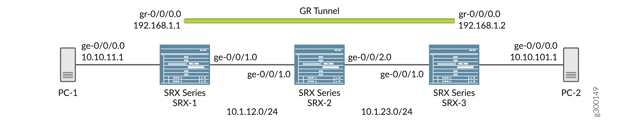
默认情况下,本地子网接口为 ge-0/0/0,IPv4 地址为 10.10.11.1/24。目标子网为 10.10.10.0/24,隧道端点 IPv4 接口为 10.10.10.1/24。
GRE 配置显示 SRX 系列防火墙上隧道接口之间的默认配置。
配置到达目标子集的路由
分步过程
您可以通过 gr 接口或使用 IGP 配置静态路由。
-
配置本地子网接口 ge-0/0/0 接口。
[edit interfaces] user@host# set interfaces ge-0/0/0 unit 0 family inet address 10.10.11.1/24 -
配置接口 ge-0/0/1。
[edit interfaces] user@host# set interfaces ge-0/0/1 unit 0 family inet address 10.1.12.1/24 -
配置 gr- 隧道端点,并将源地址、目标地址和家族指定为隧道端点的 inet。
[edit interfaces] user@host# set interfaces gr-0/0/0 unit 0 tunnel source 10.1.12.1 destination 10.1.23.1 user@host# set interfaces gr-0/0/0 unit 0 family inet address 192.168.1.1/24 -
配置的接口绑定到层
[edit security]级的安全区域。show zones使用命令查看区域。按以下步骤配置区域:[edit security zones security-zones trust]] user@host# set host-inbound-traffic system-services all user@host# set host-inbound-traffic protocols all user@host# set interfaces gr-0/0/0.0 user@host# set zones zone names protocols all[edit security zones security-zones untrust]] user@host# set host-inbound-traffic system-services all user@host# set host-inbound-traffic protocols all -
使用
show命令查看[edit interfaces]层级配置的接口。[edit interfaces] user@host# set routing options static route 10.10.10.0/24 next hop gr-0/0/0.0 -
如果您不想定义静态路由,可以在两端的 gr-0/0/0 接口和内部子网之间配置 OSPF 作为被动邻接方,以接收所有内部路由。在
[edit protocols]层次结构级别配置 OSPF 并使用show命令查看它。[edit protocols] user@host# set protocols ospf area 0.0.0.0 interface gr-0/0/0.0
结果
在配置模式下,输入 show 命令以确认您在设备上的配置。如果输出未显示预期的配置,请重复此示例中的配置说明,以便进行更正。
使用静态路由的 GRE 配置:
[edit interfaces]
root@SRX-1# show
ge-0/0/0 {
unit 0 {
family inet {
address 10.10.11.1/24;
}
}
}
gr-0/0/0 {
unit 0 {
tunnel {
source 10.1.12.1;
destination 10.1.23.1;
}
family inet {
address 192.168.1.1/24;
}
}
}
ge-0/0/1 {
unit 0 {
family inet {
address 10.1.12.1/24;
}
}
}
[edit security]
root@SRX-1# show
zones {
security-zone trust {
host-inbound-traffic {
system-services {
all;
}
protocols {
all;
}
}
interfaces {
gr-0/0/0.0;
}
}
}
root@SRX-1# show routing-options
static {
route 10.10.10.0/24 next-hop gr-0/0/0.0;
}
使用在两端的接口 gr-0/0/0 和内部子网之间配置的 OSPF 作为被动邻接方进行 GRE 配置:
[edit protocols]
root@SRX-1# show
ospf {
area 0.0.0.0 {
interface gr-0/0/0.0;
interface ge-0/0/0.0 {
passive;
}
}
}
验证
要验证 SRX 系列防火墙上的 GRE 配置是否成功,请执行以下作:
GRE 接口验证
目的
验证 GRE 接口是否已启动。
行动
show interfaces在[edit interfaces]层次结构级别运行命令:
show interfaces gr-0/0/0 terse [edit interfaces] Interface Admin Link Proto Local Remote gr-0/0/0 up up gr-0/0/0.0 up up inet 192.168.1.1/24
路由验证
目的
验证目标网络的路由是否可通过 GRE 隧道接口访问。
行动
show route forwarding-table matching 10.10.10.0/24 在[edit interfaces]层次结构级别运行命令:
[edit interfaces] user@router# run show route forwarding-table matching 10.10.10.0/24 Routing table: default.inet Internet: .... Destination Type RtRef Next hop Type Index NhRef Netif 10.10.10.0/24 user 0 ucst 595 2 gr-0/0/0.0
验证通过 GRE 隧道的流量
目的
将流量发送到目标子网,并验证 GRE 接口何时启动。
行动
运行 show interfaces gr-0/0/0 extensive 作命令。还要验证数据包是否通过 gr- 接口离开。
user@host> show interfaces gr-0/0/0 extensive Physical interface: gr-0/0/0, Enabled, Physical link is Up Interface index: 134, SNMP ifIndex: 40, Generation: 17 Type: GRE, Link-level type: GRE, MTU: Unlimited, Speed: 800mbps Hold-times : Up 0 ms, Down 0 ms Device flags : Present Running Interface flags: Point-To-Point SNMP-Traps Statistics last cleared: 2005-08-05 21:39:41 UTC (00:00:47 ago) Traffic statistics: Input bytes : 8400 0 bps Output bytes : 8400 0 bps Input packets: 100 0 pps Output packets: 100 0 pps Logical interface gr-0/0/0.0 (Index 72) (SNMP ifIndex 28) (Generation 17) Flags: Point-To-Point SNMP-Traps 16384 IP-Header 10.1.12.1:10.1.23.1:47:df:64:0000000000000000 Encapsulation: GRE-NULL Traffic statistics: Input bytes : 8400 Output bytes : 8400 Input packets: 100 Output packets: 100 Local statistics: Input bytes : 0 Output bytes : 0 Input packets: 0 Output packets: 0 Transit statistics: Input bytes : 8400 0 bps Output bytes : 8400 0 bps Input packets: 100 0 pps Output packets: 100 0 pps Protocol inet, MTU: 1476, Generation: 25, Route table: 0 Flags: None Addresses, Flags: Is-Primary Destination: Unspecified, Local: 192.168.0.1, Broadcast: Unspecified, Generation: 30
示例:配置 GRE over IPsec 隧道
要求
概述
GRE 隧道提供最低限度的安全性,而 IPsec 隧道在机密性、数据身份验证和完整性保证方面提供增强的安全性。此外,IPsec 无法直接支持组播数据包。但是,如果首先使用封装的 GRE 隧道,则可以使用 IPsec 隧道为组播数据包提供安全性。在 GRE over IPsec 隧道中,所有路由流量(IP 和非 IP)都可以通过路由。当原始数据包(IP/非 IP)对 GRE 进行封装时,它有一个由 GRE 隧道(通常是隧道接口 IP 地址)定义的 IP 报头。IPsec协议可以识别IP数据包;所以它会封装 GRE 数据包,使其成为 GRE over IPsec。
配置 GRE over IPsec 所涉及的基本步骤如下:
配置基于路由的 IPsec 隧道。
配置 GRE 隧道。
通过 gr- 接口配置以目标为远程子网的静态路由。
配置 GRE 终结点的静态路由,将 st0 接口作为下一跃点。
配置
在此示例中,默认配置的本地子网接口为 ge-0/0/0,IPv4 地址为 10.10.11.1/24。目标子网为 10.10.10.0/24。gr-0/0/0 接口隧道端点是两端的环路地址,本地环路 IPv4 地址为 172.20.1.1,远程环路 IPv4 地址为 172.20.1.2。gr-0/0/0、st0 和 lo0 接口绑定到安全区域,并相应创建策略。
通过 IPsec 隧道配置 GRE 接口
分步过程
在
[set interfaces interface-name unit unit-number]层次结构级别配置 GRE,其中接口名称为 ge-0/0/0,族设置为 inet。[edit interfaces] user@host# set interfaces ge-0/0/0 unit 0 family inet address 10.10.11.1/24
配置 gr- 隧道端点,并将源地址、目标地址和家族指定为隧道端点的 inet。
[edit interfaces] user@host# set interfaces gr-0/0/0 unit 0 tunnel source 172.20.1.1 destination 172.20.1.2 user@host# set interfaces gr-0/0/0 unit 0 family inet 192.168.1.1/24
同样,配置 lo0 和 st0 接口,将系列设置为 inet。
[edit interfaces] user@host# set interfaces lo0 unit 0 family inet address 172.20.1.1/32
[edit interfaces] user@host# set interfaces st0 unit 0 family inet
将 GRE 接口与安全区域融为一体。
show zones使用命令查看显示配置的隧道接口 lo0 和 st0 的区域。[edit security zones security-zones trust]] user@host# set host-inbound-traffic system-services all user@host# set host-inbound-traffic protocols all user@host# set interfaces gr-0/0/0.0 user@host# set zones zone names protocols all user@host# set interfaces lo0.0 user@host# set interfaces st0.0
[edit security zones security-zones untrust]] user@host# set host-inbound-traffic system-services all user@host# set host-inbound-traffic protocols all user@host# set interfaces gr-0/0/0.0.1 user@host# set interfaces lo0.0 user@host# set interfaces st0.0
结果
在配置模式下,输入 show 命令以确认您的接口配置。配置的接口绑定到层 [edit security] 级的安全区域。 show zones 使用命令查看显示已配置接口(gr-、st0.0 和 lo0)的区域。如果输出未显示预期的配置,请重复此示例中的配置说明,以便进行更正。
用于配置 GRE 接口的参数:
user@host> show interfaces
ge-0/0/0 {
    unit 0 {
        family inet {
            address 10.10.11.1/24;
        }
    }
}

gr-0/0/0 {
    unit 0 {
        tunnel {
            source 172.20.1.1;
            destination 172.20.1.2;
        }
        family inet {
            address 192.168.1.1/24;
        }
    }
}

lo0 {
    unit 0 {
        family inet {
            address 172.20.1.1/32;
        }
    }
}

st0 {
    unit 0 {
        family inet;
    }
}

[edit]
root@Juniper# show
routing-options {
    static {
        route 10.10.10.0/24 next-hop gr-0/0/0.0;
        route 172.20.1.2/32 next-hop st0.0;
    }
}
用于配置具有安全区域的 GRE 接口的参数:
[edit security]
root@Juniper# show
zones {
    security-zone trust {
        host-inbound-traffic {
            system-services {
                all;
            }
            protocols {
                all;
            }
        }
        interfaces {
            gr-0/0/0.0;
            lo0.0;
            st0.0;
        }
    }
}
示例:当隧道目标位于路由实例中时配置 GRE 隧道
要求
概述
当隧道目标位于默认路由实例或非默认路由实例中时,可以配置 GRE 隧道。配置 GRE 隧道需要定义隧道源和隧道目标地址。如果隧道目标位于路由实例中,并且存在多个路由实例,则需要指定正确的路由实例以及用于到达配置的隧道目标地址的路由表。
默认情况下,隧道目标地址被视为可使用默认路由表“inet.0”访问。
配置
在此示例中,您可以使用两个实例在 SRX 系列防火墙上的 gr- 接口之间配置 GRE 隧道。当隧道目标位于默认路由实例中,而隧道目标位于非默认路由实例中时,就会出现这些实例。
当隧道目标位于默认路由实例中时,配置 GRE 隧道
此示例使用默认路由实例到达隧道目标。因此,默认情况下使用路由表 inet.0。
分步过程
指定隧道的源地址和目标地址。
[edit interfaces]
user@host# set interfaces gr-0/0/0  unit 0 tunnel source 172.16.0.1 destination 10.10.1.2
user@host# set interfaces gr-0/0/0  unit 0 family inet 192.168.100.1/30;
配置 ge- 接口和 lo0 接口,并将家族设置为 inet。
[edit interfaces]
user@host# set interfaces ge-0/0/0 unit 0 family inet address 172.30.73.56/24
user@host# set interfaces lo0 unit 0 family inet address 172.16.0.1/32
-
为 GRE 配置主题中提到的路由选项配置 GRE 隧道接口。
当隧道目标位于非默认路由实例中时配置 GRE 隧道
对于非默认路由实例,请确保已配置 gr-0/0/0 接口。
分步过程
配置 GRE 隧道,将 gr-0/00 接口和家族设置为 inet。
[edit interfaces]
user@host# set interfaces gr-0/00 unit 0 family inet address
指定隧道的源地址和目标地址。
[edit interfaces]
user@host# set interfaces gr-0/0/0  unit 0 tunnel source 172.16.0.1 tunnel destination 10.10.1.2 family inet 192.168.100.1/30;
配置 ge- 接口和 lo0 接口,并将家族设置为 inet。
[edit interfaces]
user@host# set interfaces ge-0/0/0 unit 0 family inet address 172.30.73.56/24
user@host# set interfaces lo0 unit 0 family inet address 172.16.0.1/32
配置用于隧道接口的路由实例。
[edit routing-instances]
user@host# set routing-instances test instance-type virtual-router
user@host# set routing-instances test routing-options static route 10.10.1.2/32 next-hop 172.30.73.57
user@host# set routing-instances test interface ge-0/0/0.0
为 GRE 隧道接口配置路由实例。
[edit interfaces]
user@host# set interfaces gr-0/0/0 unit 0  tunnel routing-instance destination test
添加静态路由作为隧道目标。
[edit interfaces]
user@host# set routing-options static route 10.10.1.2/32 next-table test.inet.0
注意:当 SRX 系列防火墙处于数据包模式时,无需配置静态路由即可从 inet.0 访问隧道目标。但是,您仍然需要在 gr-0/0/0 接口下指定正确的路由实例。
结果
在配置模式下,输入 show 命令以确认您在设备上的配置。如果输出未显示预期的配置,请重复此示例中的配置说明,以便进行更正。
当隧道目标位于默认路由实例中时:
interfaces {
    gr-0/0/0 {
        unit 0 {
            tunnel {
                source 172.16.0.1;
                destination 10.10.1.2;
            }
            family inet {
                address 192.168.100.1/30;
            }
        }
    }
    ge-0/0/0 {
        unit 0 {
            family inet {
                address 172.30.73.56/24;
            }
        }
    }
    lo0 {
        unit 0 {
            family inet {
                address 172.16.0.1/32;
            }
        }
    }
    ...
}
routing-options {
    static {
        route 10.10.1.2/32 next-hop 172.30.73.57;                   # Tunnel destination is reachable from default routing-instance
        ...
    }
}
routing-instances {
    test {
        instance-type virtual-router;
        interface gr-0/0/0.0;
        routing-options {
            ...
        }
    }
}
当隧道目标位于非默认路由实例中时:
interfaces {
    gr-0/0/0 {
        unit 0 {
            tunnel {
                source 172.16.0.1;
                destination 10.10.1.2;
                routing-instance {
                    destination test;                               # Routing-instance to reach tunnel destination
                }
            }
            family inet {
                address 192.168.100.1/30;
            }
        }
    }
    ge-0/0/0 {
        unit 0 {
            family inet {
                address 172.30.73.56/24;
            }
        }
    }
    lo0 {
        unit 0 {
            family inet {
                address 172.16.0.1/32;
            }
        }
    }
    ...
}

routing-options {
         static {
         route 10.10.1.2/32 next-table test.inet.0;                 # Tunnel destination is reachable via test.inet.0
     ...
     }
}

routing-instances {
     test {
         instance-type virtual-router;
         interface ge-0/0/0;
         routing-options {
             static {
                 route 10.10.1.2/32 next-hop 172.30.73.57;          # Tunnel destination is reachable from non-default routing-instance
                 ...
             }
         }
     }
}
验证
静态路由使用验证
目的
验证是否使用了静态路由。
行动
运行命令 show route forwarding table 。
user@host> show route forwarding-table table test
No Title
Routing table: test.inet
Internet:
Enabled protocols: Bridging,
Destination        Type RtRef Next hop           Type Index    NhRef Netif
default            perm     0                    rjct      597     1
0.0.0.0/32         perm     0                    dscd      590     1
10.10.1.2/32       user     1 172.30.73.57       hold      598     4 ge-0/0/0.0
172.16.0.1.10.10.1.2.47/72
                   dest     0                    locl      617     1
172.30.73.0/24     intf     0                    rslv      588     1 ge-0/0/0.0
172.30.73.0/32     dest     0 172.30.73.0        recv      586     1 ge-0/0/0.0
172.30.73.56/32    intf     0 172.30.73.56       locl      587     2
172.30.73.56/32    dest     0 172.30.73.56       locl      587     2
172.30.73.57/32    dest     0 172.30.73.57       hold      598     4 ge-0/0/0.0
172.30.73.255/32   dest     0 172.30.73.255      bcst      585     1 ge-0/0/0.0
224.0.0.0/4        perm     0                    mdsc      596     1
224.0.0.1/32       perm     0 224.0.0.1          mcst      600     1
255.255.255.255/32 perm     0                    bcst      601     1