示例:配置基于 MPLS 的第 2 层 VPN
此示例说明如何在运行 Junos OS 的路由器或交换机上配置和验证基于 MPLS 的第 2 层 VPN。
我们的内容测试团队已验证并更新了此示例。
您可以使用运行 Junos OS 的路由器和交换机部署基于 MPLS 的第 2 层虚拟专用网络,从而将客户站点与第 2 层连接互连。第 2 层 VPN 使客户能够完全控制他们选择的传输和路由协议。
基于 MPLS 的 VPN 需要在提供商网络中实现基准 MPLS 功能。基本 MPLS 正常运行后,您就可以配置使用标签交换路径 (LSP) 通过提供商核心进行传输的 VPN。
添加 VPN 服务不会影响提供商网络中的基本 MPLS 交换操作。事实上,提供商 (P) 设备只需要基准 MPLS 配置,因为它们无法识别 VPN。VPN 状态仅在 PE 设备上维护。这也是基于 MPLS 的 VPN 如此可扩展的一个关键原因。
要求
此示例使用以下硬件和软件组件:
Junos OS 15.1 或更高版本
在 Junos OS 20.1R1 版上重新验证
两台提供商边缘 (PE) 设备
一台提供商 (P) 设备
两台客户边缘 (CE) 设备
该示例重点介绍如何将第 2 层 VPN 添加到预先存在的 MPLS 基准。提供基本 MPLS 配置,以防您的网络尚未部署 MPLS。
要支持基于 MPLS 的 VPN,底层 MPLS 基准必须提供以下功能:
面向核心的环路接口可在 MPLS 系列支持下运行
OSPF 或 IS-IS 等内部网关协议,用于在提供商(P 和 PE)设备的环路地址之间提供可访问性
一种 MPLS 信令协议,如 LDP 或 RSVP,用于向 LSP 发出信号
在 PE 设备环路地址之间建立的 LSP
参与给定 VPN 的每对 PE 设备之间都需要 LSP。最好在所有 PE 设备之间构建 LSP,以适应未来的 VPN 增长。您可以在层次结构级别配置 LSP [edit protocols mpls] 。与电路交叉连接 (CCC) 的 MPLS 配置不同,您无需手动将 LSP 与 PE 设备面向客户的(边缘)接口相关联。相反,第 2 层 VPN 使用 BGP 信令来传达第 2 层站点可访问性。此 BGP 信令可自动将远程第 2 层 VPN 站点映射到 LSP 转发下一跃点。这意味着,使用 2 层 VPN 时,不需要将 LSP 显式映射到 PE 设备的面向边缘的接口。
有关 CCC 的详细信息,请参阅 使用第 2 层电路配置基于 MPLS 的 VLAN CCC。
概述和拓扑
第 2 层 VPN 在提供商和客户网络之间实现完全隔离。第 2 层 VPN 的优势包括支持非标准传输协议,以及在客户和提供商网络之间隔离链路寻址和路由协议操作。
VPN 的定义仅涉及对本地和远程 PE 设备的更改。提供商设备上不需要其他配置(基准 MPLS 支持除外),因为这些设备仅提供基本的 MPLS 交换功能。CE 设备不使用 MPLS。它们只需要一个基本接口,如果需要,还需要协议配置,即可在第 2 层 VPN 上运行。对于第 2 层 VPN,您可以将 CE 设备配置为已连接到共享链路。
MPLS 基准就位后,您必须在 PE 设备上配置以下功能,以建立基于 MPLS 的第 2 层 VPN:
BGP 组具有
family l2vpn signaling具有实例类型的路由实例
l2vpnPE 设备上面向客户的接口必须按如下方式配置:
指定
ethernet-ccc或vlan-ccc物理层封装,具体取决于是否正在使用 VLAN 标记。在路由实例配置中配置匹配的封装类型。
使用 配置
family ccc用于第 2 层 VPN 的逻辑接口(单元)。
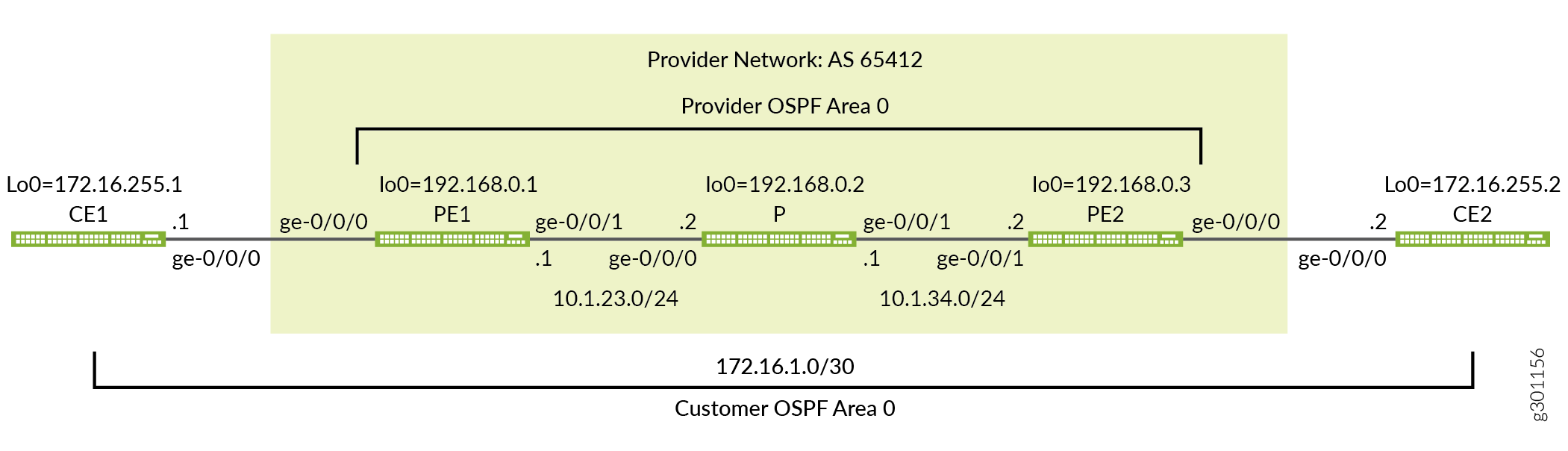
图 1 提供了此基于 MPLS 的第 2 层 VPN 示例的拓扑。该图详细介绍了提供商网络中使用的接口名称、IP 寻址和协议。它还强调了 CE 设备寻址和协议栈操作的端到端特性。与第 3 层 VPN 不同,CE 设备操作对第 2 层 VPN 中的提供商网络是不透明的。CE 设备与提供商网络之间不存在对等关系。因此,您希望 CE 设备在提供商网络 之间形成 OSPF 邻接关系,而不是与提供商网络 形成邻接关系。
快速配置
使用本节中的配置快速启动并运行基于 MPLS 的第 2 层 VPN。这些配置包括一个功能性 MPLS 基准,以支持您的第 2 层 VPN。此示例重点介绍配置的 VPN 方面。有关此示例中使用的基准 MPLS 功能的更多信息,请参阅以下链接:
CLI 快速配置
设备配置省略了管理接口、静态路由、系统日志记录、系统服务和用户登录信息。配置的这些部分因位置而异,与 MPLS 或 VPN 功能没有直接关系。
根据需要根据您的环境细节编辑以下命令,并将其粘贴到本地 CE (CE1) 设备终端窗口中:
CE1 设备的完整配置。
set system host-name ce1
set interfaces ge-0/0/0 description "Link from CE1 to PE1"
set interfaces ge-0/0/0 unit 0 family inet address 172.16.1.1/30
set interfaces lo0 unit 0 family inet address 172.16.255.1/32
set protocols ospf area 0.0.0.0 interface lo0.0
set protocols ospf area 0.0.0.0 interface ge-0/0/0.0
根据需要根据您的环境细节编辑以下命令,并将其粘贴到本地 PE (PE1) 设备终端窗口中:
PE1 设备的完整配置。
set system host-name pe1
set interfaces ge-0/0/0 description "Link from PE1 to CE1"
set interfaces ge-0/0/0 encapsulation ethernet-ccc
set interfaces ge-0/0/0 unit 0 family ccc
set interfaces ge-0/0/1 description "Link from PE1 to P-router"
set interfaces ge-0/0/1 mtu 4000
set interfaces ge-0/0/1 unit 0 family inet address 10.1.23.1/24
set interfaces ge-0/0/1 unit 0 family mpls
set interfaces lo0 unit 0 family inet address 192.168.0.1/32
set routing-instances l2vpn1 protocols l2vpn interface ge-0/0/0.0 description "EDGE LINK BETWEEN PE1 AND CE1"
set routing-instances l2vpn1 protocols l2vpn site CE-1 interface ge-0/0/0.0 remote-site-id 2
set routing-instances l2vpn1 protocols l2vpn site CE-1 site-identifier 1
set routing-instances l2vpn1 protocols l2vpn encapsulation-type ethernet
set routing-instances l2vpn1 instance-type l2vpn
set routing-instances l2vpn1 interface ge-0/0/0.0
set routing-instances l2vpn1 route-distinguisher 192.168.0.1:12
set routing-instances l2vpn1 vrf-target target:65412:12
set routing-options autonomous-system 65412
set protocols bgp group ibgp type internal
set protocols bgp group ibgp local-address 192.168.0.1
set protocols bgp group ibgp family l2vpn signaling
set protocols bgp group ibgp neighbor 192.168.0.3
set protocols mpls label-switched-path lsp_to_pe2 to 192.168.0.3
set protocols mpls interface ge-0/0/1.0
set protocols ospf traffic-engineering
set protocols ospf area 0.0.0.0 interface lo0.0
set protocols ospf area 0.0.0.0 interface ge-0/0/1.0
set protocols rsvp interface lo0.0
set protocols rsvp interface ge-0/0/1.0
P 设备的完整配置。
set system host-name p
set interfaces ge-0/0/0 description "Link from P-router to PE1"
set interfaces ge-0/0/0 mtu 4000
set interfaces ge-0/0/0 unit 0 family inet address 10.1.23.2/24
set interfaces ge-0/0/0 unit 0 family mpls
set interfaces ge-0/0/1 description "Link from P-router to PE2"
set interfaces ge-0/0/1 mtu 4000
set interfaces ge-0/0/1 unit 0 family inet address 10.1.34.1/24
set interfaces ge-0/0/1 unit 0 family mpls
set interfaces lo0 unit 0 family inet address 192.168.0.2/32
set protocols mpls interface ge-0/0/0.0
set protocols mpls interface ge-0/0/1.0
set protocols ospf traffic-engineering
set protocols ospf area 0.0.0.0 interface lo0.0
set protocols ospf area 0.0.0.0 interface ge-0/0/0.0
set protocols ospf area 0.0.0.0 interface ge-0/0/1.0
set protocols rsvp interface lo0.0
set protocols rsvp interface ge-0/0/0.0
set protocols rsvp interface ge-0/0/1.0
PE2 设备的完整配置。
set system host-name pe2
set interfaces ge-0/0/0 description "Link from PE2 to CE2"
set interfaces ge-0/0/0 encapsulation ethernet-ccc
set interfaces ge-0/0/0 unit 0 family ccc
set interfaces ge-0/0/1 description "Link from PE2 to P-router"
set interfaces ge-0/0/1 mtu 4000
set interfaces ge-0/0/1 unit 0 family inet address 10.1.34.2/24
set interfaces ge-0/0/1 unit 0 family mpls
set interfaces lo0 unit 0 family inet address 192.168.0.3/32
set routing-instances l2vpn1 protocols l2vpn interface ge-0/0/0.0 description "EDGE LINK BETWEEN PE2 AND CE2"
set routing-instances l2vpn1 protocols l2vpn site CE-2 interface ge-0/0/0.0 remote-site-id 1
set routing-instances l2vpn1 protocols l2vpn site CE-2 site-identifier 2
set routing-instances l2vpn1 protocols l2vpn encapsulation-type ethernet
set routing-instances l2vpn1 instance-type l2vpn
set routing-instances l2vpn1 interface ge-0/0/0.0
set routing-instances l2vpn1 route-distinguisher 192.168.0.3:12
set routing-instances l2vpn1 vrf-target target:65412:12
set routing-options autonomous-system 65412
set protocols bgp group ibgp type internal
set protocols bgp group ibgp local-address 192.168.0.3
set protocols bgp group ibgp family l2vpn signaling
set protocols bgp group ibgp neighbor 192.168.0.1
set protocols mpls label-switched-path lsp_to_pe1 to 192.168.0.1
set protocols mpls interface ge-0/0/1.0
set protocols ospf traffic-engineering
set protocols ospf area 0.0.0.0 interface lo0.0
set protocols ospf area 0.0.0.0 interface ge-0/0/1.0
set protocols rsvp interface lo0.0
set protocols rsvp interface ge-0/0/1.0
CE2 设备的完整配置。
set system host-name ce2
set interfaces ge-0/0/0 description "Link from CE2 to PE2"
set interfaces ge-0/0/0 unit 0 family inet address 172.16.1.2/30
set interfaces lo0 unit 0 family inet address 172.16.255.2/32
set protocols ospf area 0.0.0.0 interface lo0.0
set protocols ospf area 0.0.0.0 interface ge-0/0/0.0
当您的工作感到满意时,请务必在所有设备上提交配置更改。恭喜您全新基于 MPLS 的第 2 层 VPN!请参阅 验证 部分,了解确认 VPN 按预期工作所需的步骤。
为基于 MPLS 的第 2 层 VPN 配置本地 PE (PE1) 设备
本节介绍为此示例配置 PE1 设备所需的步骤。有关此示例中使用的客户边缘设备和 P 设备配置,请参阅 示例:配置基于 MPLS 的第 2 层 VPN 部分。
配置 MPLS 基准(如果需要)
在配置第 2 层 VPN 之前,请确保 PE 设备具有有效的 MPLS 基准。如果您已有 MPLS 基准,则可以跳到将第 2 层 VPN 添加到本地 PE 设备的分步过程。
-
配置主机名。
[edit]
user@pe1# set system host-name pe1
-
配置接口。
[edit]
user@pe1# set interfaces ge-0/0/1 description "Link from PE1 to P-router"
[edit]
user@pe1# set interfaces ge-0/0/1 mtu 4000
[edit]
user@pe1# set interfaces ge-0/0/1 unit 0 family inet address 10.1.23.1/24
[edit]
user@pe1# set interfaces ge-0/0/1 unit 0 family mpls
[edit]
user@pe1# set interfaces lo0 unit 0 family inet address 192.168.0.1/32
谨慎:第 2 层 VPN 不支持提供商网络中的分段。提供商网络必须支持 CE 设备在 PE 设备添加 MPLS 和虚拟路由和转发 (VRF) 标签 后 可以生成的最大帧,这一点至关重要。此示例将 CE 设备保留为默认的 1500 字节最大传输单元 (MTU),同时将提供商核心配置为支持 4000 字节 MTU。此配置通过确保 CE 设备不能超过提供商网络中的 MTU 来避免丢弃。
-
配置协议。
注意:RSVP 信号 LSP 支持流量工程,但基本 MPLS 交换或 VPN 部署不需要流量工程。提供的 MPLS 基准使用 RSVP 向 LSP 发出信号,并为 OSPF 启用流量工程。但是,未配置路径约束,因此您希望通过内部网关协议的最短路径路由 LSP。
[edit
]user@pe1# set protocols ospf area 0.0.0.0 interface lo0.0
[edit]
user@pe1# set protocols ospf area 0.0.0.0 interface ge-0/0/1.0
[edit]
user@pe1# set protocols ospf traffic-engineering
[edit]
user@pe1# set protocols mpls interface ge-0/0/1.0
[edit]
user@pe1# set protocols rsvp interface lo0.0
[edit]
user@pe1# set protocols rsvp interface ge-0/0/1.0
-
将 LSP 定义为远程 PE 设备的环路地址。
[edit]
user@pe1#  set protocols mpls label-switched-path lsp_to_pe2 to 192.168.0.3
程序
分步过程
按照以下步骤为第 2 层 VPN 配置 PE1 设备。
配置面向边缘的接口。指定与单元
family ccc0 上的物理封装类型ethernet-ccc。这是未标记以太网接口的唯一有效单元号。如果使用 VLAN 标记,请指定vlan-ccc封装并将 CCC 系列添加到所需的单元。提示:您可以在同一 PE 设备上配置基于 MPLS 的第 2 层 VPN 和基于 MPLS 的第 3 层 VPN。但是,您不能将同一个面向客户的边缘接口配置为同时支持第 2 层 VPN 和第 3 层 VPN。
[edit]user@pe1# set interfaces ge-0/0/0 encapsulation ethernet-ccc
[edit]
user@pe1# set interfaces ge-0/0/0 unit 0 family ccc
[edit]
user@pe1# set interfaces ge-0/0/0 description "Link from PE1 to CE1"
注意:第 2 层 VPN 要求在物理设备级别使用 CCC 封装配置 PE 设备的面向边缘的接口,并在单元级别配置 CCC 系列。无论是部署 CCC、基于 MPLS 的第 2 层 VPN 还是基于 MPLS 的第 3 层 VPN,提供商设备的配置方式都相同。这是因为它们没有面向边缘的接口或 VPN 感知能力。
为本地和远程 PE 设备之间的对等互连配置 BGP 组。使用 PE 设备的环路地址作为本地地址并启用
family l2vpn signaling。[edit protocols bgp] user@pe1# set group ibgp local-address 192.168.0.1 family l2vpn signaling
将 BGP 组类型配置为内部。
[edit protocols bgp]
user@pe1# set group ibgp type internal
将远程 PE 设备的环路地址配置为 BGP 邻居。
[edit protocols bgp]
user@pe1# set group ibgp neighbor 192.168.0.3
配置 BGP 自治系统编号。
[edit routing-options]
user@pe1# set autonomous-system 65412
配置路由实例。首先指定实例名称 l2vpn1,并带有
instance-type的l2vpn。[edit routing-instances] user@pe1# set l2vpn1 instance-type l2vpn
将 PE 设备的面向客户的接口配置为属于路由实例。
[edit routing-instances]
user@pe1# set l2vpn1 interface ge-0/0/0
配置路由实例的路由识别符。此设置用于区分从特定 PE 设备上的特定 VRF 发送的路由。对于每个 PE 设备上的每个路由实例,它应该是唯一的。
[edit routing-instances]
user@pe1# set l2vpn1 route-distinguisher 192.168.0.1:12
配置实例的虚拟路由和转发 (VRF) 表路由目标。该
vrf-target语句将指定的社区标记添加到所有通告的路由,同时自动匹配路由导入的相同值。要在共享给定 VPN 的 PE 设备上配置匹配的路由目标,才能进行正确的路由交换。[edit routing-instances] user@pe1# set l2vpn1 vrf-target target:65412:12
l2vpn在实例中配置协议并指定在面向边缘的链路上使用的封装。如果边缘接口已标记 VLAN,请确保指定ethernet-vlan。[edit routing-instances] user@pe1# set l2vpn1 protocols l2vpn encapsulation-type ethernet
在实例节
l2vpn下添加面向边缘的界面以及描述。[edit routing-instances] user@pe1# set l2vpn1 protocols l2vpn interface ge-0/0/0.0 description "L2vpn Link Between PE1 and CE1"
配置第 2 层 VPN 站点信息,并将面向边缘的接口与本地客户站点关联。
[edit routing-instances]
user@pe1# set l2vpn1 protocols l2vpn site CE-1 site-identifier 1 interface ge-0/0/0.0 remote-site-id 2
注意:在此示例中,PE1 设备的站点 ID 为 1,PE2 设备的站点 ID 为 2。对于本地 PE 设备 (PE1),远程站点的值为 2 已正确配置
remote-site-id。在 PE1 设备上提交更改并返回到 CLI 操作模式。
[edit]
user@pe1# commit and-quit
结果
显示 PE1 设备上的配置结果。输出仅反映此示例中添加的功能配置。
user@pe1> show configuration
interfaces {
    ge-0/0/0 {
        description "Link from PE1 to CE1";
        encapsulation ethernet-ccc;
        unit 0 {
            family ccc;
        }
    }
    ge-0/0/1 {
        description "Link from PE1 to P-router";
        mtu 4000;
        unit 0 {
            family inet {
                address 10.1.23.1/24;
            }
            family mpls;
        }
    }
    lo0 {
        unit 0 {
            family inet {
                address 192.168.0.1/32;
            }
        }
    }
}
routing-instances {
    l2vpn1 {
        protocols {
            l2vpn {
                interface ge-0/0/0.0 {
                    description "L2vpn Link Between PE1 and CE1" ;
                }
                site CE-1 {
                    interface ge-0/0/0.0 {
                        remote-site-id 2;
                    }
                    site-identifier 1;
                }
                encapsulation-type ethernet;
            }
        }
        instance-type l2vpn;
        interface ge-0/0/0.0;
        route-distinguisher 192.168.0.1:12;
        vrf-target target:65412:12;
    }
}
routing-options {
    autonomous-system 65412;
}
protocols {
    bgp {
        group ibgp {
            type internal;
            local-address 192.168.0.1;
            family l2vpn {
                signaling;
            }
            neighbor 192.168.0.3;
        }
    }
    mpls {
        label-switched-path lsp_to_pe2 {
            to 192.168.0.3;
        }
        interface ge-0/0/1.0;
    }
    ospf {
        traffic-engineering;
        area 0.0.0.0 {
            interface lo0.0;
            interface ge-0/0/1.0;
        }
    }
    rsvp {
        interface lo0.0;
        interface ge-0/0/1.0;
    }
}
为基于 MPLS 的第 2 层 VPN 配置远程 PE (PE2) 设备
本节介绍为此示例配置 PE2 设备所需的步骤。有关此示例中使用的客户边缘设备和 P 设备配置,请参阅 示例:配置基于 MPLS 的第 2 层 VPN 部分。
配置 MPLS 基准(如果需要)
在配置第 2 层 VPN 之前,请确保 PE 设备具有有效的 MPLS 基准。如果您已有 MPLS 基准,则可以跳到将第 2 层 VPN 添加到本地 PE 设备的分步过程。
-
配置主机名。
[edit]
user@pe2# set system host-name pe2
-
配置接口。
[edit]
user@pe2# set interfaces ge-0/0/1 description "Link from PE2 to P-router"
[edit]
user@pe2# set interfaces ge-0/0/1 mtu 4000
[edit]
user@pe2# set interfaces ge-0/0/1 unit 0 family inet address 10.1.34.2/24
[edit]
user@pe2# set interfaces ge-0/0/1 unit 0 family mpls
[edit]
user@pe2# set interfaces lo0 unit 0 family inet address 192.168.0.3/32
谨慎:第 2 层 VPN 不支持提供商网络中的分段。提供商网络必须支持 CE 设备在 PE 设备添加 MPLS 和虚拟路由和转发 (VRF) 标签 后 可以生成的最大帧,这一点至关重要。此示例将 CE 设备保留为默认的 1500 字节最大传输单元 (MTU),同时将提供商核心配置为支持 4000 字节 MTU。此配置通过确保 CE 设备不能超过提供商网络中的 MTU 来避免丢弃。
-
配置协议。
注意:RSVP 信号 LSP 支持流量工程,但基本 MPLS 交换或 VPN 部署不需要流量工程。提供的 MPLS 基准使用 RSVP 向 LSP 发出信号,并为 OSPF 启用流量工程。但是,未配置路径约束,因此您希望通过内部网关协议的最短路径路由 LSP。
[edit]
user@pe2# set protocols ospf area 0.0.0.0 interface lo0.0
[edit]
user@pe2# set protocols ospf area 0.0.0.0 interface ge-0/0/1.0
[edit]
user@pe2# set protocols ospf traffic-engineering
[edit]
user@pe2# set protocols mpls interface ge-0/0/1.0
[edit]
user@pe2# set protocols rsvp interface lo0.0
[edit]
user@pe2# set protocols rsvp interface ge-0/0/1.0
-
将 LSP 定义为远程 PE 设备的环路地址。
[edit]
user@pe2#  set protocols mpls label-switched-path lsp_to_pe1 to 192.168.0.1
程序
分步过程
按照以下步骤为第 2 层 VPN 配置 PE2 设备。
配置面向边缘的接口封装和系列。回想一下,这是一个未标记的接口,因此只有单元 0 对家族有效
ccc。[edit]user@pe2# set interfaces ge-0/0/0 encapsulation ethernet-ccc [edit] user@pe2# set interfaces ge-0/0/0 unit 0 family ccc [edit] user@pe1# set interfaces ge-0/0/0 description "Link from PE2 to CE2"
配置 BGP 组。将 PE 设备的环路地址指定为本地地址并启用
family l2vpn signaling。[edit protocols bgp] user@pe2# set group ibgp local-address 192.168.0.3 family l2vpn signaling
将 BGP 组类型配置为内部。
[edit protocols bgp]
user@pe2# set group ibgp type internal
将 PE1 设备配置为 BGP 邻接方。请务必将 PE1 的环路地址指定为 BGP 邻居。
[edit protocols bgp]
user@pe2# set group ibgp neighbor 192.168.0.1
配置 BGP 自治系统编号。
[edit routing-options]
user@pe2# set autonomous-system 65412
配置路由实例。首先指定实例名称l2vpn1
instance-type(使用 ofl2vpn)。[edit routing-instances] user@pe2# set l2vpn1 instance-type l2vpn
将 PE 设备的面向客户的边缘接口配置为属于路由实例。
[edit routing-instances]
user@pe2# set l2vpn1 interface ge-0/0/0
配置实例的路由识别符。
[edit routing-instances]
user@pe2# set l2vpn1 route-distinguisher 192.168.0.3:12
配置实例的 VPN 虚拟路由和转发 (VRF) 表路由目标。分配的目标必须与 PE1 设备上配置的目标匹配。
[edit routing-instances]
user@pe2# set l2vpn1 vrf-target target:65412:12
为协议配置
l2vpn实例并指定在面向边缘的链路上使用的封装。[edit routing-instances] user@pe2# set l2vpn1 protocols l2vpn encapsulation-type ethernet
在实例的
l2vpn层次结构下添加 PE 设备的面向边缘的接口以及说明。[edit routing-instances] user@pe2# set l2vpn1 protocols l2vpn interface ge-0/0/0.0 description "L2vpn Link Between PE2 and CE2"
配置实例的第 2 层 VPN 站点信息,并在本地站点下列出 PE 设备的面向边缘的接口。在 PE2 设备上配置的本地站点 ID 必须与您在 PE1 设备上配置的远程站点 ID 匹配,反之亦然。
[edit routing-instances]
user@pe1# set l2vpn1 protocols l2vpn site CE-2 site-identifier 2 interface ge-0/0/0.0 remote-site-id 1
注意:在此示例中,PE2 设备的站点 ID 为 2,PE1 设备的站点 ID 为 1。对于 PE2 设备,远程站点的值为 1 已正确配置
remote-site-id。在 PE2 设备上提交更改并返回到 CLI 操作模式。
[edit]
user@pe1# commit and-quit
结果
显示 PE2 设备上的配置结果。
user@pe2# show
interfaces {
    ge-0/0/0 {
        description "Link from PE2 to CE2";
        encapsulation ethernet-ccc;
        unit 0 {
            family ccc;
        }
    }
    ge-0/0/1 {
        description "Link from PE2 to P-router";
        mtu 4000;
        unit 0 {
            family inet {
                address 10.1.34.2/24;
            }
            family mpls;
        }
    }
    lo0 {
        unit 0 {
            family inet {
                address 192.168.0.3/32;
            }
        }
    }
}
routing-instances {
    l2vpn1 {
        protocols {
            l2vpn {
                interface ge-0/0/0.0 {
                    description "L2vpn Link Between PE2 and CE2" ;
                }
                site CE-2 {
                    interface ge-0/0/0.0 {
                        remote-site-id 1;
                    }
                    site-identifier 2;
                }
                encapsulation-type ethernet;
            }
        }
        instance-type l2vpn;
        interface ge-0/0/0.0;
        route-distinguisher 192.168.0.3:12;
        vrf-target target:65412:12;
    }
}
routing-options {
    autonomous-system 65412;
}
protocols {
    bgp {
        group ibgp {
            type internal;
            local-address 192.168.0.3;
            family l2vpn {
                signaling;
            }
            neighbor 192.168.0.1;
        }
    }
    mpls {
        label-switched-path lsp_to_pe1 {
            to 192.168.0.1;
        }
        interface ge-0/0/1.0;
    }
    ospf {
        traffic-engineering;
        area 0.0.0.0 {
            interface lo0.0;
            interface ge-0/0/1.0;
        }
    }
    rsvp {
        interface lo0.0;
        interface ge-0/0/1.0;
    }
}
验证
执行以下任务以验证基于 MPLS 的第 2 层 VPN 是否正常工作:
- 验证提供商 OSPF 邻接和路由交换
- 验证 MPLS 和 RSVP 接口设置
- 验证 RSVP 信号 LSP
- 验证 BGP 会话状态
- 验证路由表中的第 2 层 VPN 路由
- 验证第 2 层 VPN 连接状态
- 使用第 2 层 VPN 连接 ping 远程 PE 设备
- 验证客户边缘设备在第 2 层 VPN 上的端到端操作
验证提供商 OSPF 邻接和路由交换
目的
通过验证邻接状态和到远程提供商设备环路地址的 OSPF 获知路由,确认 OSPF 协议在提供商网络中正常工作。正确的 IGP 操作对于成功建立 MPLS LSP 至关重要。
行动
user@pe1> show ospf neighbor

Address          Interface              State           ID               Pri  Dead
10.1.23.2        ge-0/0/1.0             Full            192.168.0.2      128    38
user@pe1> show route protocol ospf | match 192.168

192.168.0.2/32     *[OSPF/10] 1w5d 20:48:59, metric 1
192.168.0.3/32     *[OSPF/10] 2w0d 00:08:30, metric 2
意义
输出显示 PE1 设备已与 P 设备建立 OSPF 邻接关系 (192.168.0.2)。它还显示,P 和远程 PE 设备环路地址 () 和 (192.168.0.2192.168.0.3) 是通过本地 PE 设备上的 OSPF 获知的。
验证 MPLS 和 RSVP 接口设置
目的
验证 RSVP 和 MPLS 协议是否配置为在 PE 设备的面向核心的接口上运行。此步骤还会验证 family mpls 在面向内核的接口的单元级别是否正确配置了该配置。
行动
user@pe1> show mpls interface

Interface        State       Administrative groups (x: extended)
ge-0/0/1.0       Up         <none>
user@pe1> show rsvp interface

RSVP interface: 2 active
                          Active  Subscr- Static      Available   Reserved    Highwater
Interface          State  resv    iption  BW          BW          BW          mark
ge-0/0/1.0             Up       1   100%  1000Mbps    1000Mbps    0bps        0bps
lo0.0                  Up       0   100%  0bps        0bps        0bps        0bps
意义
输出显示,MPLS 和 RSVP 已在本地 PE 设备的面向核心的环路接口上正确配置。
验证 RSVP 信号 LSP
目的
验证 PE 设备之间是否正确建立了 RSVP 会话(入口和出口)。
行动
user@pe1> show rsvp session

To              From            State   Rt Style Labelin Labelout LSPname
192.168.0.3     192.168.0.1     Up       0  1 FF       -   299888 lsp_to_pe2
Total 1 displayed, Up 1, Down 0

Egress RSVP: 1 sessions
To              From            State   Rt Style Labelin Labelout LSPname
192.168.0.1     192.168.0.3     Up       0  1 FF       3        - lsp_to_pe1
Total 1 displayed, Up 1, Down 0

Transit RSVP: 0 sessions
Total 0 displayed, Up 0, Down 0
意义
输出显示,PE 设备之间已正确建立入口和出口 RSVP 会话。成功建立 LSP 表示 MPLS 基线正在运行。
验证 BGP 会话状态
目的
验证 PE 设备之间的 BGP 会话是否已正确建立,并支持第 2 层 VPN 网络层可达性信息 (NLRI)。
行动
user@pe1> show bgp summary
Threading mode: BGP I/O
Groups: 1 Peers: 1 Down peers: 0
Table          Tot Paths  Act Paths Suppressed    History Damp State    Pending
bgp.l2vpn.0
                       1          1          0          0          0          0
Peer                     AS      InPkt     OutPkt    OutQ   Flaps Last Up/Dwn State|#Active/Received/Accepted/Damped...
192.168.0.3           65412          6          5       0       0        1:34 Establ
  bgp.l2vpn.0: 1/1/1/0
  l2vpn1.l2vpn.0: 1/1/1/0
意义
输出显示到远程 PE 设备 () 的 BGP 会话已正确建立 (),并通过现场显示会话处于当前状态的时间 (192.168.0.3Establ1:34)。Up/Dwn它还显示发送到远程 PE 设备 () 和从 (56) 接收的 BGP 数据包数。该flaps字段确认未发生状态转换 (0),表示会话稳定。另请注意,第 2 层 VPN NLRI 在 PE 设备之间正确交换。此输出确认 PE 设备之间的 BGP 对等互连已准备好支持第 2 层 VPN。
验证路由表中的第 2 层 VPN 路由
目的
验证 PE1 设备上的路由表中是否填充了用于在客户边缘设备之间转发流量的第 2 层 VPN 路由。
行动
user@pe1> show route table bgp.l2vpn.0

bgp.l2vpn.0: 1 destinations, 1 routes (1 active, 0 holddown, 0 hidden)
+ = Active Route, - = Last Active, * = Both

192.168.0.3:12:2:1/96
                   *[BGP/170] 00:51:36, localpref 100, from 192.168.0.3
                      AS path: I, validation-state: unverified
                    >  to 10.1.23.2 via ge-0/0/1.0, label-switched-path lsp_to_pe2
user@pe1> show route table l2vpn1.l2vpn.0

l2vpn1.l2vpn.0: 2 destinations, 2 routes (2 active, 0 holddown, 0 hidden)
+ = Active Route, - = Last Active, * = Both

192.168.0.1:12:1:1/96
                   *[L2VPN/170/-101] 01:48:30, metric2 1
                       Indirect
192.168.0.3:12:2:1/96
                   *[BGP/170] 00:51:57, localpref 100, from 192.168.0.3
                      AS path: I, validation-state: unverified
                    >  to 10.1.23.2 via ge-0/0/1.0, label-switched-path lsp_to_pe2
意义
该命令 show route table bgp.l2vpn.0 将显示 PE 设备上已接收的所有第 2 层 VPN 路由。该命令 show route table l2vpn1.l2vpn.0 显示由于匹配路由目标而导入路由实例的第 l2vpn1 2 层 VPN 路由。该 l2vpn1.l2vpn.0 表包含本地 PE 设备的第 2 层 VPN 路由,以及通过与远程 PE 设备的 BGP 对等获知的远程路由。两个表均显示远程第 2 层 VPN 路由已正确与 lsp_to_pe2 LSP 关联,作为转发下一跃点。输出确认本地 PE 设备已从 PE2 设备获知远程客户站点。它还表明,它可以使用提供商网络上的 MPLS 传输将第 2 层 VPN 流量转发到 PE2 设备。
验证第 2 层 VPN 连接状态
目的
验证第 2 层 VPN 连接的状态。
行动
user@pe1> show l2vpn connections

Layer-2 VPN connections:

Legend for connection status (St)
EI -- encapsulation invalid      NC -- interface encapsulation not CCC/TCC/VPLS
EM -- encapsulation mismatch     WE -- interface and instance encaps not same
VC-Dn -- Virtual circuit down    NP -- interface hardware not present
CM -- control-word mismatch      -> -- only outbound connection is up
CN -- circuit not provisioned    <- -- only inbound connection is up
OR -- out of range               Up -- operational
OL -- no outgoing label          Dn -- down
LD -- local site signaled down   CF -- call admission control failure
RD -- remote site signaled down  SC -- local and remote site ID collision
LN -- local site not designated  LM -- local site ID not minimum designated
RN -- remote site not designated RM -- remote site ID not minimum designated
XX -- unknown connection status  IL -- no incoming label
MM -- MTU mismatch               MI -- Mesh-Group ID not available
BK -- Backup connection          ST -- Standby connection
PF -- Profile parse failure      PB -- Profile busy
RS -- remote site standby        SN -- Static Neighbor
LB -- Local site not best-site   RB -- Remote site not best-site
VM -- VLAN ID mismatch           HS -- Hot-standby Connection

Legend for interface status
Up -- operational
Dn -- down

Instance: l2vpn1
Edge protection: Not-Primary
  Local site: CE-1 (1)
    connection-site           Type  St     Time last up          # Up trans
    2                         rmt   Up     Jul 28 10:47:18 2020           1
      Remote PE: 192.168.0.3, Negotiated control-word: Yes (Null)
      Incoming label: 800009, Outgoing label: 800006
      Local interface: ge-0/0/0.0, Status: Up, Encapsulation: ETHERNET
      Flow Label Transmit: No, Flow Label Receive: No
意义
St输出中的字段显示到 at connection-site 2 的第 Remote PE 192.168.0.3 2 层 VPN 连接为 Up。输出还确认 PE 设备的面向边缘的接口名称和ge-0/0/0.0操作状态up为 。您还可以验证 PE 设备面向客户的接口上是否配置了以太网封装。这是此示例中使用的未标记以太网接口的正确封装。到目前为止执行的验证步骤表明,第 2 层 VPN 的控制平面正在运行。您可以通过以下步骤验证第 2 层 VPN 的数据平面。
使用第 2 层 VPN 连接 ping 远程 PE 设备
目的
验证本地和远程 PE 设备之间的第 2 层 VPN 连接。显示了命令的 ping mpls l2vpn 两种形式。两者都测试 PE 设备之间的第 2 层 VPN 路由和 MPLS 转发。第一个命令假定单个远程站点,而第二个命令指定本地和远程站点标识符,这在测试多站点第 2 层 VPN 时非常有用。这是因为远程站点 ID 可用于定位所需的远程 PE 设备。
该 ping mpls l2vpn 命令可验证 PE 设备之间的第 2 层 VPN 路由交换和 MPLS 转发。这是通过生成从本地 PE 的第 2 层 VPN 路由实例到远程 PE 设备的 127.0.0.1 环路地址的流量来实现的。此命令不会验证 CE 设备接口的操作或其配置。这是因为 CE 设备操作对于第 2 层 VPN 中的提供商网络是不透明的。
行动
user@pe1> ping mpls l2vpn interface ge-0/0/0.0 reply-mode ip-udp

!!!!!
--- lsping statistics ---
5 packets transmitted, 5 packets received, 0% packet loss
user@pe1> ping mpls l2vpn instance l2vpn1 remote-site-id 2 local-site-id 1 detail

Request for seq 1, to interface 334, labels <800002, 299840>, packet size 88
Reply for seq 1, return code: Egress-ok, time: 593.784 ms
        Local transmit time: 2020-07-13 16:15:55 UTC 241.357 ms
        Remote receive time: 2020-07-13 16:15:55 UTC 835.141 ms
Request for seq 2, to interface 334, labels <800002, 299840>, packet size 88
Reply for seq 2, return code: Egress-ok, time: 591.700 ms
        Local transmit time: 2020-07-13 16:15:56 UTC 241.405 ms
        Remote receive time: 2020-07-13 16:15:56 UTC 833.105 ms
Request for seq 3, to interface 334, labels <800002, 299840>, packet size 88
Reply for seq 3, return code: Egress-ok, time: 626.084 ms
        Local transmit time: 2020-07-13 16:15:57 UTC 241.407 ms
        Remote receive time: 2020-07-13 16:15:57 UTC 867.491 ms
Request for seq 4, to interface 334, labels <800002, 299840>, packet size 88
Reply for seq 4, return code: Egress-ok, time: 593.061 ms
        Local transmit time: 2020-07-13 16:15:58 UTC 241.613 ms
        Remote receive time: 2020-07-13 16:15:58 UTC 834.674 ms
Request for seq 5, to interface 334, labels <800002, 299840>, packet size 88
Reply for seq 5, return code: Egress-ok, time: 594.192 ms
        Local transmit time: 2020-07-13 16:15:59 UTC 241.357 ms
        Remote receive time: 2020-07-13 16:15:59 UTC 835.549 ms

--- lsping statistics ---
5 packets transmitted, 5 packets received, 0% packet loss
意义
输出确认第 2 层 VPN 转发平面在 PE 设备之间正常运行。
验证客户边缘设备在第 2 层 VPN 上的端到端操作
目的
验证客户边缘设备之间的第 2 层 VPN 连接。此步骤确认 CE 设备具有操作接口,并且已针对第 2 层连接进行了正确配置。这是通过验证 CE 设备是否已建立 OSPF 邻接关系以及是否能够在其环路地址之间端到端传递流量来完成的。
行动
user@ce1> show ospf neighbor

Address          Interface              State           ID               Pri  Dead
172.16.1.2       ge-0/0/0.0             Full            172.16.255.2     128    32
user@ce1> show ospf route | match 172

172.16.255.2/32    *[OSPF/10] 01:34:50, metric 1
                    >  to 172.16.1.2 via ge-0/0/0.0
user@ce1> ping 172.16.255.2 size 1472 do-not-fragment count 2

PING 172.16.255.2 (172.16.255.2): 1472 data bytes
1480 bytes from 172.16.255.2: icmp_seq=0 ttl=64 time=4.404 ms
1480 bytes from 172.16.255.2: icmp_seq=1 ttl=64 time=5.807 ms

--- 172.16.255.2 ping statistics ---
2 packets transmitted, 2 packets received, 0% packet loss
round-trip min/avg/max/stddev = 4.404/5.106/5.807/0.702 ms
意义
输出显示 CE 设备之间的第 2 层 VPN 连接工作正常。它确认本地客户边缘设备已通过提供商核心与远程客户边缘设备建立了 OSPF 邻接关系,并且本地客户边缘设备已通过 OSPF 学习到远程客户边缘设备 172.16.1.2环路地址 172.16.255.2 的路由。输出还显示,CE 设备能够传递 1500 字节的 IP 数据包,而不会引起本地分段。成功的 ping 操作还会验证帧未超过提供商网络支持的 MTU。
size添加到命令中的ping参数会生成 1472 字节的回显数据。额外增加了 8 字节的互联网控制消息协议 (ICMP) 和 20 字节的 IP 报头,使总数据包大小达到 1500 字节。do-not-fragment添加交换机可确保 CE 设备无法根据其本地 MTU 执行分段。此方法确认在 CE 设备之间发送标准长度以太网帧时,不可能或不需要分段。