示例:为 EVPN VXLAN A/A 多宿主配置 LACP
此示例说明如何在以太网 VPN (EVPN) VXLAN 主动-主动多宿主网络中的多宿主客户边缘 (CE) 和提供商边缘 (PE) 设备上配置链路聚合控制协议 (LACP)。
要求
此示例使用以下硬件和软件组件:
三台配置为 PE 设备的 QFX10002、QFX5100、QFX5110、QFX5200 交换机或QFX5100虚拟机箱,以及一台配置为 CE 设备的QFX5100交换机。
在所有交换机上运行 Junos OS 17.1 或更高版本。
概述
如需其他级别的冗余,您可以通过在多宿主 CE-PE 链路的两个端点上配置 LACP 来配置 EVPN VXLAN 主动-主动多宿主。多宿主设备配置了聚合中继链路,其中 CE-PE 链路的链路聚合组 (LAG) 接口可以处于活动状态,也可以处于备用状态。当LAG接口处于活动状态时,数据流量通过CE-PE链路传输。当 LAG 接口处于备用状态时,数据流量将被阻止,并且仅通过链路传输用于通信 LAG 接口状态的控制流量。
LACP 监控并作 LAG 接口,以确保多宿主 PE 设备与核心隔离时快速收敛。当核心发生故障时,隔离的 PE 设备可能会出现空路由。但是,由于 CE-PE 链路支持 LACP,在进行核心隔离时,多宿主 PE 设备面向 CE 的接口会设置为待机状态,从而阻塞多宿主 PE 设备之间的数据流量传输。核心从故障中恢复后,接口状态会从待机切换回活动状态。
在 QFX10002 和 QFX10008 交换机上,仅支持使用 VXLAN 进行 EVPN 主动-主动多宿主的 LACP。
在 CE-PE 链路上配置 LACP 时,多宿主 PE 设备与核心的隔离按如下方式进行:
LACP 对等方同步配置和作数据。
LACP 对等方通过交换控制 PDU 进行同步,并且由于以下原因而需要:
确定以太网捆绑包中链路的状态(全活动或备用)。
在 PE 设备上配置 LACP 端口密钥时,检测并处理 CE 设备配置错误。
在 PE 设备上配置 LACP 端口密钥时,检测并处理 CE 和 PE 设备之间的接线错误。
当 LACP 发言者无法收敛时,检测参与者或合作伙伴流失并对其做出响应。
当多宿主 PE 设备的对等方为 null 时,PE 设备将与核心隔离。在这种情况下,隔离式 PE 设备会通知连接到隔离式 PE 设备的 CE 设备发生核心故障。
数据流量不会从CE设备转发到隔离的多宿主PE设备。相反,流量会被转移到属于同一 LAG 的其他多宿主 PE 设备。这可以防止隔离 PE 设备出现流量黑洞。
如果多宿主 CE 设备使用 LAG 将流量负载平衡到多个活动多宿主 PE 设备,则 LACP 配置以及所有多宿主 PE 设备上为该给定 LAG 配置的相同系统 ID 将触发 LACP 与所有连接的多宿主 CE 链路不同步。
在多宿主设备上配置 LACP 时,请注意以下注意事项:
无论 UP/DOWN作状态如何,LAG 链路都可以在活动或备用状态下运行。
重新启动系统时,多宿主 PE 设备上的 LACP 链路处于活动状态。
当控制平面关闭时,系统会通知 LACP 为聚合端口运行多路复用器状态机,并将链路从活动变为备用。
接口不会被视为已启动,除非该接口在活动状态下运行,并且其作状态也为已启动。
拓扑学
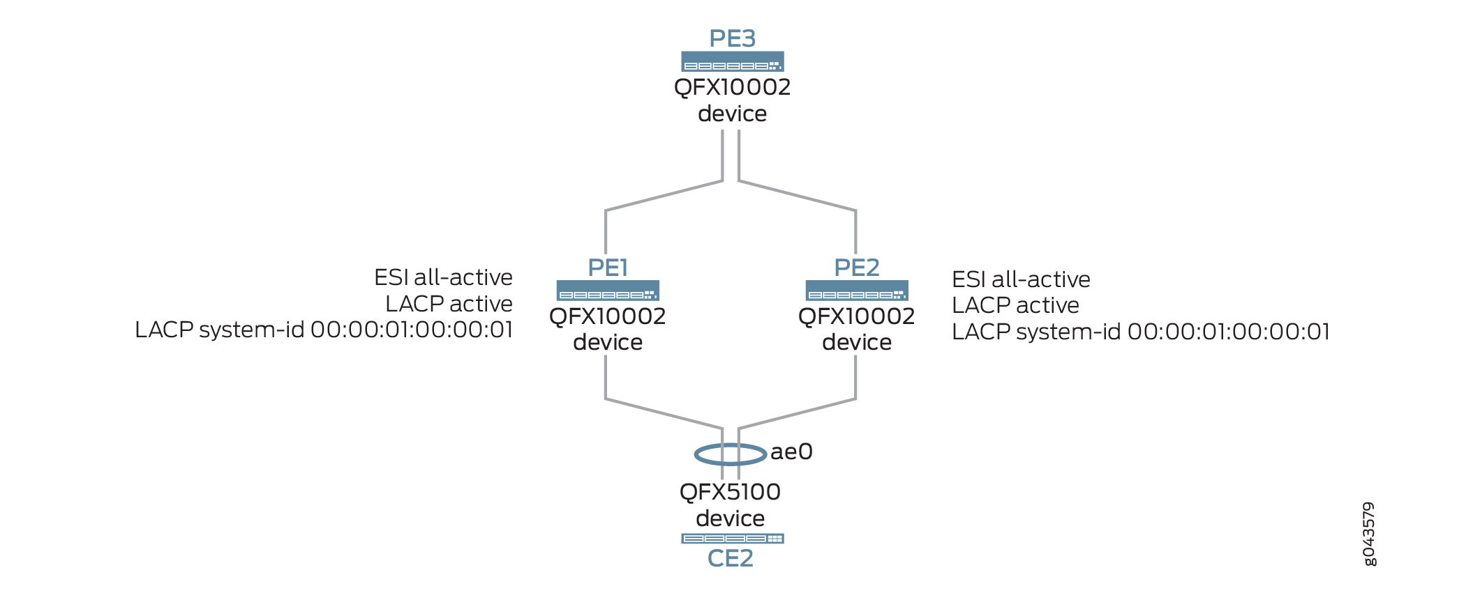
图 1 展示了在多宿主 CE 和 PE 设备上配置了 LACP 的 EVPN VXLAN 主动-主动多宿主网络。设备 CE1 为单宿主设备,可连接到远程 PE1 和 PE2 设备。设备 CE2 与 PE1 和 PE2 设备多宿主。
 中的 LACP 支持
例如,设备 PE1 的核心隔离按如下方式处理:
PE2 和 PE1 建立 BGP 会话后,LACP 会将 CE-PE 链路的状态设置为解除阻塞模式。
当出现核心故障时,可能会导致设备 CE1 出现空路由。
为防止出现这种情况,面向设备 CE2 的 LAG 接口会通过 LACP 从活动状态更改为待机状态。
LACP 在连接的多宿主 CE2 链路上发送不同步通知,以阻止设备 CE2 和设备 PE1 之间的流量传输。
当控制平面恢复时,设备 PE2 会通过 LACP 从待机切换回活动状态。
配置
- CLI 快速配置
- 为 PE3 上的 EVPN A/A 多宿主配置 LACP
- 为 PE1 上的 EVPN 主动-主动多宿主配置 LACP
- 为 PE2 上的 EVPN A/A 多宿主配置 LACP
- 在 CE2 上为 EVPN A/A 多宿主配置 LACP
CLI 快速配置
要快速配置此示例,请复制以下命令,将其粘贴到文本文件中,删除所有换行符,更改详细信息,以便与网络配置匹配,将命令复制并粘贴到层 [edit] 级的 CLI 中,然后从配置模式进入 commit 。
设备 PE3
set interfaces xe-0/0/0 unit 0 family inet address 10.10.10.1/24
set interfaces xe-0/0/2 unit 0 family inet address 10.12.12.1/24
set interfaces xe-0/0/4 unit 0 family inet address 10.14.14.1/24
set interfaces xe-0/0/8 unit 0 family ethernet-switching interface-mode trunk
set interfaces xe-0/0/8 unit 0 family ethernet-switching vlan members all
set interfaces lo0 unit 0 family inet address 10.2.3.1/32 primary
set vlans v100 vlan-id 100
set vlans v200 vlan-id 200
set vlans v100 vxlan vni 100
set vlans v200 vxlan vni 200
set routing-options router-id 10.2.3.1
set routing-options autonomous-system 65011
set switch-options vtep-source-interface lo0.0
set switch-options route-distinguisher 10.2.3.1:1
set switch-options vrf-target target:1111:11
set protocols bgp group pe type internal
set protocols bgp group pe local-address 10.2.3.1
set protocols bgp group pe family evpn signaling
set protocols bgp group pe neighbor 10.2.3.3
set protocols bgp group pe neighbor 10.2.3.4
set protocols ospf area 0.0.0.0 interface xe-0/0/2
set protocols ospf area 0.0.0.0 interface lo0 passive
set protocols ospf area 0.0.0.0 interface xe-0/0/0
set protocols ospf area 0.0.0.0 interface xe-0/0/4
set protocols evpn encapsulation vxlan
set protocols evpn extended-vni-list all
设备 PE1
set chassis aggregated-devices ethernet device-count 1
set interfaces xe-0/0/2 unit 0 family inet address 10.12.12.2/24
set interfaces xe-0/0/3 unit 0 family inet address 10.11.11.2/24
set interfaces xe-0/0/9 unit 0 family ethernet-switching interface-mode trunk
set interfaces xe-0/0/9 unit 0 family ethernet-switching vlan members v200
set interfaces ae0 unit 0 family ethernet-switching interface-mode trunk
set interfaces ae0 unit 0 family ethernet-switching vlan members all
set interfaces xe-0/0/55:0 ether-options 802.3ad ae0
set interfaces ae0 esi 00:03:03:03:03:03:03:03:03:03
set interfaces ae0 esi all-active
set interfaces ae0 aggregated-ether-options lacp active
set interfaces ae0 aggregated-ether-options lacp system-id 00:00:01:00:00:01
set interfaces lo0 unit 0 family inet address 10.2.3.3/32 primary
set vlans v100 vlan-id 100
set vlans v200 vlan-id 200
set vlans v100 vxlan vni 100
set vlans v200 vxlan vni 200
set routing-options router-id 10.2.3.3
set routing-options autonomous-system 65011
set switch-options vtep-source-interface lo0
set switch-options route-distinguisher 10.2.3.3:1
set switch-options vrf-target target:1111:11
set protocols bgp group pe type internal
set protocols bgp group pe local-address 10.2.3.3
set protocols bgp group pe family evpn signaling
set protocols bgp group pe neighbor 10.2.3.1
set protocols bgp group pe neighbor 10.2.3.4
set protocols ospf area 0.0.0.0 interface xe-0/0/2
set protocols ospf area 0.0.0.0 interface lo0.0 passive
set protocols ospf area 0.0.0.0 interface xe-0/0/3
set protocols evpn encapsulation vxlan
set protocols evpn extended-vni-list all
设备 PE2
set chassis aggregated-devices ethernet device-count 1
set interfaces xe-0/0/2 unit 0 family inet address 10.14.14.2/24
set interfaces xe-0/0/5 unit 0 family ethernet-switching interface-mode trunk
set interfaces xe-0/0/5 unit 0 family ethernet-switching vlan members all
set interfaces ae0 unit 0 family ethernet-switching interface-mode trunk
set interfaces ae0 unit 0 family ethernet-switching vlan members all
set interfaces xe-0/0/55:0 ether-options 802.3ad ae0
set interfaces ae0 esi 00:03:03:03:03:03:03:03:03:03
set interfaces ae0 esi all-active
set interfaces ae0 aggregated-ether-options lacp active
set interfaces ae0 aggregated-ether-options lacp system-id 00:00:01:00:00:01
set interfaces lo0 unit 0 family inet address 10.2.3.4/32 primary
set vlans v100 vlan-id 100
set vlans v200 vlan-id 200
set vlans v100 vxlan vni 100
set vlans v200 vxlan vni 200
set routing-options router-id 10.2.3.4
set routing-options autonomous-system 65011
set switch-options vtep-source-interface lo0
set switch-options route-distinguisher 10.2.3.4:1
set switch-options vrf-target target:1111:11
set protocols bgp group pe type internal
set protocols bgp group pe local-address 10.2.3.4
set protocols bgp group pe family evpn signaling
set protocols bgp group pe neighbor 10.2.3.1
set protocols bgp group pe neighbor 10.2.3.2
set protocols bgp group pe neighbor 10.2.3.3
set protocols ospf area 0.0.0.0 interface xe-0/0/2
set protocols ospf area 0.0.0.0 interface lo0 passive
set protocols evpn encapsulation vxlan
set protocols evpn extended-vni-list all
设备 CE2
set vlans v100 vlan-id 100
set vlans v200 vlan-id 200
set interfaces xe-0/0/3 unit 0 family ethernet-switching interface-mode trunk
set interfaces xe-0/0/3 unit 0 family ethernet-switching vlan members all
set interfaces xe-0/0/5 ether-options 802.3ad ae0
set interfaces xe-0/0/0 ether-options 802.3ad ae0
set interfaces ae0 unit 0 family ethernet-switching interface-mode trunk
set interfaces ae0 unit 0 family ethernet-switching vlan members all
set interfaces ae0 aggregated-ether-options lacp active
为 PE3 上的 EVPN A/A 多宿主配置 LACP
分步过程
下面的示例要求您在各个配置层级中进行导航。有关 CLI 导航的信息,请参阅 CLI 用户指南中的在配置模式下使用 CLI 编辑器。
要配置设备 PE3,请执行以下作:
配置指向 PE1 和 PE2 设备的上行链路接口。
[edit interfaces]
user@CE1# set xe-0/0/0 unit 0 family inet address 10.10.10.1/24
user@CE1# set xe-0/0/2 unit 0 family inet address 12.12.12.1/24
user@CE1# set xe-0/0/4 unit 0 family inet address 14.14.14.1/24
将 xe-0/0/8 配置为第 2 层接口。
[edit interfaces]
user@CE1# set xe-0/0/8 unit 0 family ethernet-switching interface-mode trunk
user@CE1# set xe-0/0/8 unit 0 family ethernet-switching vlan members all
配置环路接口。
[edit interfaces]
user@CE1# set lo0 unit 0 family inet address 10.2.3.1/32 primary
创建 VLAN v100 和 v200。
[edit vlans]
user@CE1# set v100 vlan-id 100
user@CE1# set v200 vlan-id 200
将 VLAN v100 和 v200 映射到 VNI 100 和 200。
[edit vlans]
user@CE1# set v100 vxlan vni 100
user@CE1# set v200 vxlan vni 200
配置路由器 ID 和自治系统编号。
[edit routing-options]
user@CE1# set router-id 10.2.3.1
user@CE1# set autonomous-system 65011
将环路接口指定为 VTEP 隧道的源地址。
[edit switch-options]
user@CE1# set vtep-source-interface lo0.0
指定路由识别符以唯一标识从此设备发送的路由。
[edit switch-options]
user@CE1# set route-distinguisher 10.2.3.1:1
指定全局 VRF 导出策略。
[edit switch-options]
user@CE1# set vrf-target target:1111:11
为 PE3 配置内部 BGP 组,以便与 PE1 和 PE2 对等。
[edit protocols]
user@CE1# set bgp group pe type internal
user@CE1# set bgp group pe local-address 10.2.3.1
user@CE1# set bgp group pe family evpn signaling
user@CE1# set bgp group pe neighbor 10.2.3.3
user@CE1# set bgp group pe neighbor 10.2.3.4
配置 OSPF 区域。
[edit protocols]
user@CE1# set ospf area 0.0.0.0 interface xe-0/0/2
user@CE1# set ospf area 0.0.0.0 interface lo0 passive
user@CE1# set ospf area 0.0.0.0 interface xe-0/0/0
user@CE1# set ospf area 0.0.0.0 interface xe-0/0/4
将 VXLAN 设置为 EVPN 的数据平面封装。
[edit protocols]
user@CE1# set evpn encapsulation vxlan
指定所有 VNI 都由 EVPN 播发。
[edit protocols]
user@CE1# set evpn extended-vni-list all
结果
在配置模式下,输入show chassis、show protocolsshow interfacesshow routing-options和show routing-instances命令,以确认您的配置。如果输出未显示预期的配置,请重复此示例中的说明以更正配置。
user@PE3# show interfaces
xe-0/0/0 {
    unit 0 {
        family inet {
            address 10.10.10.1/24;
        }
    }
}
xe-0/0/2 {
    unit 0 {
        family inet {
            address 10.10.6.1/30;
            address 10.12.12.1/24;
        }
    }
}
xe-0/0/4 {
    unit 0 {
        family inet {
            address 10.14.14.1/24;
        }
    }
}
xe-0/0/8 {
    unit 0 {
        family ethernet-switching {
            interface-mode trunk;
            vlan {
                members all;
            }
        }
    }
}
lo0 {
    unit 0 {
        family inet {
            address 10.10.0.1/32;
            address 10.2.3.1/32 {
                primary;
            }
        }
    }
}
user@PE3# show vlans
v100 {
    vlan-id 100;
    vxlan {
        vni 100;
    }
}
v200 {
    vlan-id 200;
    vxlan {
        vni 200;
    }
}
user@PE3# show routing-options
router-id 10.2.3.1;
autonomous-system 65011;
user@PE3# show switching-options
vtep-source-interface lo0;
route-distinguisher 10.2.3.1:1;
vrf-target target:1111:11;
user@PE3# show protocols bgp
group pe {
    type internal;
    local-address 10.2.3.1;
    family evpn {
        signaling;
    }
    neighbor 10.2.3.3;
    neighbor 10.2.3.4;
}
user@PE3# show protocols ospf
area 0.0.0.0 {
    interface lo0.0 {
        passive;
    }
    interface xe-0/0/2;
    interface xe-0/0/0;
    interface xe-0/0/4;
}
如果完成设备配置,请从配置模式输入 commit 。
为 PE1 上的 EVPN 主动-主动多宿主配置 LACP
分步过程
下面的示例要求您在各个配置层级中进行导航。有关 CLI 导航的信息,请参阅 CLI 用户指南中的在配置模式下使用 CLI 编辑器。
要配置设备 PE1,请执行以下作:
指定要在设备 PE1 上创建的聚合以太网接口数。
[edit chassis]
user@PE1# set aggregated-devices ethernet device-count 1
配置连接到 CE 设备的接口。
[edit interfaces]
user@PE1# set xe-0/0/2 unit 0 family inet address 10.12.12.2/24
user@PE1# set xe-0/0/2 unit 0 family inet address 10.11.11.2/24
将 xe-0/0/9 配置为第 2 层接口。
[edit interfaces]
user@PE1# set xe-0/0/9 unit 0 family ethernet-switching interface-mode trunk
user@PE1# set xe-0/0/9 unit 0 family ethernet-switching vlan members v200
将 ae0 配置为第 2 层接口。
[edit interfaces]
user@PE1# set ae0 unit 0 family ethernet-switching interface-mode trunk
user@PE1# set ae0 unit 0 family ethernet-switching vlan members all
配置面向多宿主设备 CE2 的接口。
在 CE2 多宿主的所有 PE 设备上使用相同的 ESI 值。
[edit interfaces]
user@PE1# set xe-0/0/55:0 ether-options 802.3ad ae0
user@PE1# set ae0 esi 00:03:03:03:03:03:03:03:03:03
user@PE1# set ae0 esi all-active
在 ae0 上配置 LACP。
在 CE2 多宿主的所有 PE 设备上使用相同的系统 ID 值。
[edit interfaces]
user@PE1# set ae0 aggregated-ether-options lacp active
user@PE1# set ae0 aggregated-ether-options lacp system-id 00:00:01:00:00:01
配置环路接口。
[edit interfaces]
user@PE1# set lo0 unit 0 family inet address 10.2.3.3/32 primary
创建 VLAN v100 和 v200。
[edit vlans]
user@PE1# set v100 vlan-id 100
user@PE1# set v200 vlan-id 200
将 VLAN v100 和 v200 映射到 VNI 100 和 200。
[edit vlans]
user@PE1# set v100 vxlan vni 100
user@PE1# set v200 vxlan vni 200
配置路由器 ID 和自治系统编号。
[edit routing-options]
user@PE1# set router-id 10.2.3.3
user@PE1# set autonomous-system 65011
将环路接口指定为 VTEP 隧道的源地址。
[edit switch-options]
user@PE1# set vtep-source-interface lo0.0
指定路由识别符以唯一标识从此设备发送的路由。
[edit switch-options]
user@PE1# set route-distinguisher 10.2.3.3:1
指定全局 VRF 导出策略。
[edit switch-options]
user@PE1# set vrf-target target:1111:11
为 PE3 配置内部 BGP 组,以便与 PE1 和 PE2 对等。
[edit protocols]
user@PE1# set bgp group pe type internal
user@PE1# set bgp group pe local-address 10.2.3.3
user@PE1# set bgp group pe family evpn signaling
user@PE1# set bgp group pe neighbor 10.2.3.1
user@PE1# set bgp group pe neighbor 10.2.3.4
配置 OSPF 区域。
[edit protocols]
user@PE1# set ospf area 0.0.0.0 interface xe-0/0/2
user@PE1# set ospf area 0.0.0.0 interface lo0 passive
user@PE1# set ospf area 0.0.0.0 interface xe-0/0/3
将 VXLAN 设置为 EVPN 的数据平面封装。
[edit protocols]
user@PE1# set evpn encapsulation vxlan
指定所有 VNI 都由 EVPN 播发。
[edit protocols]
user@PE1# set evpn extended-vni-list all
结果
在配置模式下,输入show chassis、show protocolsshow interfacesshow routing-options和show routing-instances命令,以确认您的配置。如果输出未显示预期的配置,请重复此示例中的说明以更正配置。
user@PE1# show chassis
aggregated-devices {
    ethernet {
        device-count 1;
    }
}
user@PE1# show interfaces
xe-0/0/2 {
    unit 0 {
        family inet {
            address 10.10.6.1/30;
            address 10.12.12.1/24;
            address 10.12.12.2/24;
        }
    }
}
xe-0/0/3 {
    unit 0 {
        family inet {
            address 10.11.11.2/24;
        }
    }
}
xe-0/0/9 {
    unit 0 {
        family ethernet-switching {
            interface-mode trunk;
            vlan {
                members v200;
            }
        }
    }
}
xe-0/0/55:0 {
    ether-options {
        802.3ad ae0;
    }
}
ae0 {
    esi {
        00:03:03:03:03:03:03:03:03:03;
        all-active;
    }
    aggregated-ether-options {
        lacp {
            active;
            system-id 00:00:01:00:00:01;
        }
    }
    unit 0 {
        family ethernet-switching {
            interface-mode trunk;
            vlan {
                members all;
            }
        }
    }
}
user@PE1# show vlans
v100 {
    vlan-id 100;

    vxlan {
        vni 100;
    }
}
v200 {
    vlan-id 200;

    vxlan {
        vni 200;
    }
}
user@PE1# show routing-options
router-id 10.2.3.3;
autonomous-system 65011;
user@PE1# show switching-options
vtep-source-interface lo0;
route-distinguisher 10.2.3.3:1;
vrf-target target:1111:11;
user@PE1# show protocols bgp
group pe {
    type internal;
    local-address 10.2.3.3;
    family evpn {
        signaling;
    }
    neighbor 10.2.3.3;
    neighbor 10.2.3.4;
    neighbor 10.2.3.1;
}
user@PE1# show protocols ospf
area 0.0.0.0 {
    interface lo0 {
        passive;
    }
    interface xe-0/0/2;
    interface xe-0/0/3;
}
user@PE1# show protocols evpn
encapsulation vxlan;
extended-vni-list all;
如果完成设备配置,请从配置模式输入 commit 。
为 PE2 上的 EVPN A/A 多宿主配置 LACP
分步过程
下面的示例要求您在各个配置层级中进行导航。有关 CLI 导航的信息,请参阅 CLI 用户指南中的在配置模式下使用 CLI 编辑器。
要配置设备 PE2,请执行以下作:
指定要在设备 PE1 上创建的聚合以太网接口数。
[edit chassis]
user@PE2# set aggregated-devices ethernet device-count 1
配置连接到 CE 设备的接口。
[edit interfaces]
user@PE2# set xe-0/0/2 unit 0 family inet address 10.14.14.2/24
将 xe-0/0/5 配置为第 2 层接口。
[edit interfaces]
user@PE2# set xe-0/0/5 unit 0 family ethernet-switching interface-mode trunk
user@PE2# set xe-0/0/5 unit 0 family ethernet-switching vlan members v200
将 ae0 配置为第 2 层接口。
[edit interfaces]
user@PE2# set ae0 unit 0 family ethernet-switching interface-mode trunk
user@PE2# set ae0 unit 0 family ethernet-switching vlan members all
配置面向多宿主设备 CE2 的接口。
在 CE2 多宿主的所有 PE 设备上使用相同的 ESI 值。
[edit interfaces]
user@PE2# set xe-0/0/55:0 ether-options 802.3ad ae0
user@PE2# set ae0 esi 00:03:03:03:03:03:03:03:03:03
user@PE2# set ae0 esi all-active
在 ae0 上配置 LACP。
在 CE2 多宿主的所有 PE 设备上使用相同的系统 ID 值。
[edit interfaces]
user@PE2# set ae0 aggregated-ether-options lacp active
user@PE2# set ae0 aggregated-ether-options lacp system-id 00:00:01:00:00:01
配置环路接口。
[edit interfaces]
user@PE2# set lo0 unit 0 family inet address 10.2.3.4/32 primary
创建 VLAN v100 和 v200。
[edit vlans]
user@PE2# set v100 vlan-id 100
user@PE2# set v200 vlan-id 200
将 VLAN v100 和 v200 映射到 VNI 100 和 200。
[edit vlans]
user@PE2# set v100 vxlan vni 100
user@PE2# set v200 vxlan vni 200
配置路由器 ID 和自治系统编号。
[edit routing-options]
user@PE2# set router-id 10.2.3.4
user@PE2# set autonomous-system 65011
将环路接口指定为 VTEP 隧道的源地址。
[edit switch-options]
user@PE2# set vtep-source-interface lo0.0
指定路由识别符以唯一标识从此设备发送的路由。
[edit switch-options]
user@PE2# set route-distinguisher 10.2.3.4:1
指定全局 VRF 导出策略。
[edit switch-options]
user@PE2# set vrf-target target:1111:11
为 PE3 配置内部 BGP 组,以便与 PE1 和 PE2 对等。
[edit protocols]
user@PE2# set bgp group pe type internal
user@PE2# set bgp group pe local-address 10.2.3.4
user@PE2# set bgp group pe family evpn signaling
user@PE2# set bgp group pe neighbor 10.2.3.1
user@PE2# set bgp group pe neighbor 10.2.3.2
user@PE2# set bgp group pe neighbor 10.2.3.3
配置 OSPF 区域。
[edit protocols]
user@PE2# set ospf area 0.0.0.0 interface xe-0/0/2
user@PE2# set ospf area 0.0.0.0 interface lo0 passive
将 VXLAN 设置为 EVPN 的数据平面封装。
[edit protocols]
user@PE2# set evpn encapsulation vxlan
指定所有 VNI 都由 EVPN 播发。
[edit protocols]
user@PE2# set evpn extended-vni-list all
结果
在配置模式下,输入show chassis、show protocolsshow interfacesshow routing-options和show routing-instances命令,以确认您的配置。如果输出未显示预期的配置,请重复此示例中的说明以更正配置。
user@PE2# show chassis
aggregated-devices {
    ethernet {
        device-count 1;
    }
}
user@PE2# show interfaces
xe-0/0/2 {
    unit 0 {
        family inet {
            address 10.14.14.2/24;
        }
    }
}
xe-0/0/5 {
    unit 0 {
        family ethernet-switching {
            interface-mode trunk;
            vlan {
                members all;
            }
        }
    }
}
xe-0/0/55:0 {
    ether-options {
        802.3ad ae0;
    }
}
ae0 {
    esi {
        00:03:03:03:03:03:03:03:03:03;
        all-active;
    }
    aggregated-ether-options {
        lacp {
            active;
            system-id 00:00:01:00:00:01;
        }
    }
    unit 0 {
        family ethernet-switching {
            interface-mode trunk;
            vlan {
                members all;
            }
        }
    }
}
lo0 {
    unit 0 {
        family inet {
            address 10.2.3.4/32 {
                primary;
            }
        }
    }
}
user@PE2# show vlans
v100 {
    vlan-id 100;

    vxlan {
        vni 100;
    }
}
v200 {
    vlan-id 200;

    vxlan {
        vni 200;
    }
}
user@PE2# show routing-options
router-id 10.2.3.4;
autonomous-system 65011;
user@PE2# show switching-options
vtep-source-interface lo0;
route-distinguisher 10.2.3.4:1;
vrf-target target:1111:11;
user@PE2# show protocols bgp
group pe {
    type internal;
    local-address 10.2.3.4;
    family evpn {
        signaling;
    }
    neighbor 10.2.3.3;
    neighbor 10.2.3.4;
    neighbor 10.2.3.1;
}
user@PE2# show protocols ospf
area 0.0.0.0 {
    interface lo0 {
        passive;
    }
    interface xe-0/0/2;
}
user@PE2# show protocols evpn
encapsulation vxlan;
extended-vni-list all;
如果完成设备配置,请从配置模式输入 commit 。
在 CE2 上为 EVPN A/A 多宿主配置 LACP
分步过程
下面的示例要求您在各个配置层级中进行导航。有关 CLI 导航的信息,请参阅 CLI 用户指南中的在配置模式下使用 CLI 编辑器。
要配置设备 CE1,请执行以下作:
配置 VLAN v100 和 v200。
[edit vlans]
user@CE2# set v100 vlan-id 100
user@CE2# set v200 vlan-id 200
将 xe-0/0/3 配置为第 2 层接口。
[edit interfaces]
user@CE2# set xe-0/0/3 unit 0 family ethernet-switching interface-mode trunk
user@CE2# set xe-0/0/3 unit 0 family ethernet-switching vlan members all
将成员接口添加到 ae0。
[edit interfaces]
user@CE2# set xe-0/0/0 ether-options 802.3ad ae0
user@CE2# set xe-0/0/5 ether-options 802.3ad ae0
将 ae0 配置为第 2 层接口。
[edit interfaces]
user@CE2# set ae0 unit 0 family ethernet-switching interface-mode trunk
user@CE2# set ae0 unit 0 family ethernet-switching vlan members all
将 LACP 配置为 ae0 的活动状态。
[edit interfaces]
user@CE2# set ae0 aggregated-ether-options lacp active
结果
在配置模式下,输入show chassis、show protocolsshow interfacesshow routing-options和show routing-instances命令,以确认您的配置。如果输出未显示预期的配置,请重复此示例中的说明以更正配置。
user@CE2# show interfaces
xe-0/0/0 {
    ether-options {
        802.3ad ae0;
    }
}
xe-0/0/3 {
    unit 0 {
        family ethernet-switching {
            interface-mode trunk;
            vlan {
                members all;
            }
        }
    }
}
user@CE2# show vlans
v100 {
    vlan-id 100;
    vxlan {
        vni 100;
    }
}
v200 {
    vlan-id 200;
    vxlan {
        vni 200;
    }
}
如果完成设备配置,请从配置模式输入 commit 。
验证
确认配置工作正常。
验证 PE1 的 LACP 接口状态
目的
验证设备 PE1 上的 LACP 接口状态。
行动
在作模式下,运行 show lacp interfaces 命令。
user@PE1> show lacp interfaces
Aggregated interface: ae0
    LACP state:       Role   Exp   Def  Dist  Col  Syn  Aggr  Timeout  Activity
      xe-0/0/55:0     Actor   No    No   Yes  Yes  Yes   Yes     Fast    Active
      xe-0/0/55:0     Partner No    No   Yes  Yes  Yes   Yes     Fast    Active
    LACP protocol:    Receive State  Transmit State      Mux State
      xe-0/0/55:0     Current        Fast periodic       Collecting distributing
意义
LACP LAG 接口状态为活动。
在我们的示例中,所有链路和协议都可以运行。当用于以太网 VPN (EVPN) 的所有 BGP 会话均关闭时,核心隔离功能将激活。在此状态下,叶将关闭 LACP 以防止连接的设备发送数据。在叶交换机上,LACP 接口状态将更新为显示核心隔离关闭 (CDN)。为了演示我们在叶上停用了 BGP。LACP 接口状态已更新,以显示核心隔离已生效:
user@PE1> show lacp interfaces
Aggregated interface: ae0
    LACP state:         Role   Exp   Def  Dist  Col  Syn  Aggr  Timeout  Activity
      xe-0/0/55:0 CDN Actor   No    No    No   No   No   Yes     Fast    Active
      xe-0/0/55:0 CDN Partner No    No    No   No   Yes   Yes    Fast    Active
    LACP protocol:      Receive State  Transmit State          Mux State
      xe-0/0/55:0       Current         Fast periodic          Waiting
验证 PE2 的 LACP 接口状态
目的
验证设备 PE2 上的 LACP 接口状态。
行动
在作模式下,运行 show lacp interfaces 命令。
user@PE2> show lacp interfaces
Aggregated interface: ae0
    LACP state:       Role   Exp   Def  Dist  Col  Syn  Aggr  Timeout  Activity
      xe-0/0/55:0     Actor   No    No   Yes  Yes  Yes   Yes     Fast    Acttive
      xe-0/0/55:0     Partner No    No   Yes  Yes  Yes   Yes     Fast    Active
    LACP protocol:    Receive State  Transmit State          Mux State
      xe-0/0/55:0     Current        Fast periodic           Collecting distributing
意义
LACP LAG 接口状态为活动。