示例:通过配置出口单速率双色监管器在出口网络边界执行 CoS
此示例说明如何配置出口单速率双色监管器。监管人员使用一个称为令牌桶的概念。监管者对合同内和合同外流量实施服务等级 (CoS) 策略。您可以对传入数据包和/或传出数据包应用单速率双色监管器。此示例将监管器用作输出(出口)监管器。此示例是一个展示流量管制操作的示例,介绍了监管。
本文不涉及令牌桶概念及其底层算法的全面解释。有关流量管制和 CoS 常规信息的更多信息,请参阅 Miguel Barreiros 和 Peter Lundqvist 作者的 QOS-Enabled Networks — 工具和基础 。许多在线书商和 www.juniper.net/books 都提供这本书。
要求
为了验证此过程,此示例使用流量生成器。流量生成器可以是基于硬件的,也可以是基于服务器或主机上运行的软件。
运行 Junos OS 的设备上广泛支持此过程中的功能。此处展示的示例已在运行 Junos OS 10.4 版的 MX 系列路由器上进行了测试和验证。
概述
单速率双色监管通过对不符合限制的流量应用隐式或配置的操作,为特定服务级别实施配置的流量速率。当您在接口上对输入或输出流量应用单速率双色监管器时,监管器将流量计量为以下组件定义的速率限制:
带宽限制 — 接口处接收或传输的数据包每秒允许的平均比特数。您可以将带宽限制指定为每秒绝对位数或 1 到 100 的百分比值。如果指定了百分比值,则有效带宽限制按物理接口介质速率或逻辑接口配置的整形速率的百分比计算。
突发大小限制 — 突发数据允许的最大大小。突发大小以字节为单位。我们推荐使用两种公式来计算突发大小:
突发大小 = 带宽 x 突发流量允许的时间 / 8
或
突发大小 = 接口 mtu x 10
有关配置突发大小的信息,请参阅 确定适当的流量监管器突发大小。
注意:接口的缓冲区空间有限。通常,接口的总缓冲区深度估计约为 125 毫秒。
对于符合配置限制(归类为绿色流量)的流量,数据包将隐式地标记为数据包丢失优先级 (PLP) 级别为低,并允许无限制地通过接口。
对于超过配置限制的流量(归类为红色流量),将根据为监管器配置的流量管制操作来处理数据包。此示例丢弃超过 15 KBps 限制爆发的数据包。
要限制第 3 层流量的速率,可以通过以下方式应用双色监管器:
直接连接到特定协议级别的逻辑接口。
作为特定协议级别应用于逻辑接口的标准无状态防火墙过滤器的操作。这就是此示例中使用的技术。
要限制第 2 层流量的速率,只能将双色监管器应用为逻辑接口监管器。您无法通过防火墙过滤器对第 2 层流量应用双色监管器。
您可以选择带宽限制或监管器内的带宽百分比,因为它们相互排斥。您不能将监管器配置为将带宽百分比用于聚合接口、隧道接口或软件接口。
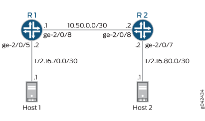
在此示例中,主机是模拟 Web 服务器的流量生成器。设备 R1 和 R2 由服务提供商拥有。Web 服务器由设备 R2 背后的用户访问。主机将使用源 TCP HTTP 端口 80 向用户发送流量。系统配置了单速率双色监管器,并将其应用于连接到设备 R2 的设备 R1 上的接口。监管器实施 Web 服务器所有者(在此案例中由主机模拟)与拥有设备 R1 和 R2 的服务提供商之间的合同带宽可用性,以便通过连接设备 R1 和 R2 的链路传输 Web 流量。
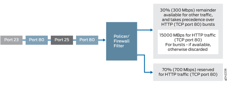
根据 Web 服务器所有者和设备 R1 和 R2 的服务提供商之间的合同带宽可用性,监管器将限制源自主机的 HTTP 端口 80 流量,使其使用 700 Mbps(70%)的可用带宽,允许的突发率为设备 R1 和 R2 之间千兆以太网接口 MTU 大小的 10 倍。
在实际场景中,您可能还会对 FTP、SFTP、SSH、TELNET、SMTP、IMAP 和 POP3 等各种其他端口的流量进行速率限制,因为它们通常作为 Web 托管服务附加服务包括在内。
您需要保留一些额外的带宽,这些带宽不会对网络控制协议(如路由协议、DNS 和保持网络连接正常运行所需的任何其他协议)进行速率限制。这就是防火墙过滤器有最终接受条件的原因。
配置
程序
CLI 快速配置
要快速配置此示例,请复制以下命令,将其粘贴到文本文件中,删除所有换行符,更改详细信息,以便与网络配置匹配,然后将命令复制并粘贴到层级的 [edit] CLI 中。
设备 R1
set interfaces ge-2/0/5 description to-Host
set interfaces ge-2/0/5 unit 0 family inet address 172.16.70.2/30
set interfaces ge-2/0/8 description to-R2
set interfaces ge-2/0/8 unit 0 family inet address 10.50.0.1/30
set interfaces ge-2/0/8 unit 0 family inet filter output mf-classifier
set interfaces lo0 unit 0 description looback-interface
set interfaces lo0 unit 0 family inet address 192.168.13.1/32
set firewall policer discard if-exceeding bandwidth-limit 700m
set firewall policer discard if-exceeding burst-size-limit 15k
set firewall policer discard then discard
set firewall family inet filter mf-classifier term t1 from protocol tcp
set firewall family inet filter mf-classifier term t1 from port 80
set firewall family inet filter mf-classifier term t1 then policer discard
set firewall family inet filter mf-classifier term t2 then accept
set protocols ospf area 0.0.0.0 interface ge-2/0/5.0 passive
set protocols ospf area 0.0.0.0 interface lo0.0 passive
set protocols ospf area 0.0.0.0 interface ge-2/0/8.0
设备 R2
set interfaces ge-2/0/7 description to-Host
set interfaces ge-2/0/7 unit 0 family inet address 172.16.80.2/30
set interfaces ge-2/0/8 description to-R1
set interfaces ge-2/0/8 unit 0 family inet address 10.50.0.2/30
set interfaces lo0 unit 0 description looback-interface
set interfaces lo0 unit 0 family inet address 192.168.14.1/32
set protocols ospf area 0.0.0.0 interface ge-2/0/7.0 passive
set protocols ospf area 0.0.0.0 interface lo0.0 passive
set protocols ospf area 0.0.0.0 interface ge-2/0/8.0
逐步过程
以下示例要求您在配置层次结构中的各个级别上导航。有关如何操作的说明,请参阅 Junos OS CLI 用户指南中的在配置模式下使用 CLI 编辑器。
要配置设备 R1:
配置设备接口。
[edit interfaces]
user@R1#set ge-2/0/5 description to-Host
user@R1#set ge-2/0/5 unit 0 family inet address 172.16.70.2/30
user@R1#set ge-2/0/8 description to-R2
user@R1#set ge-2/0/8 unit 0 family inet address 10.50.0.1/30
user@R1# set lo0 unit 0 description looback-interface
user@R1#set lo0 unit 0 family inet address 192.168.13.1/32
将监管器配置为将速率限制为 700 Mbps 的带宽和 15 KBps 的 HTTP 流量突发大小(TCP 端口 80)。
[edit firewall policer discard]
user@R1# set if-exceeding bandwidth-limit 700m
user@R1# set if-exceeding burst-size-limit 15k
配置监管器以丢弃红色流量中的数据包。
[edit firewall policer discard]
user@R1# set then discard
将防火墙的两个条件配置为接受到端口 HTTP(端口 80)的所有 TCP 流量。
[edit firewall  family inet filter mf-classifier]
user@R1# set term t1 from protocol tcp
user@R1# set term t1 from port 80
使用监管器配置防火墙操作以限制 HTTP TCP 流量的速率。
[edit firewall  family inet filter mf-classifier]
user@R1# set term t1 then policer discard
在防火墙过滤器结束时,配置接受所有其他流量的默认操作。
否则,到达接口且防火墙未明确接受的所有流量将被丢弃。
[edit firewall  family inet filter mf-classifier]
user@R1# set term t2 then accept
将防火墙过滤器应用于接口 ge-2/0/8,作为输出过滤器。
[edit interfaces ge-2/0/8 unit 0 family inet]
user@R1# set filter output mf-classifier
配置 OSPF。
[edit protocols ospf]
user@R1# set area 0.0.0.0 interface ge-2/0/5.0 passive
user@R1# set area 0.0.0.0 interface lo0.0 passive
user@R1# set area 0.0.0.0 interface ge-2/0/8.0
逐步过程
要配置设备 R2:
配置设备接口。
[edit interfaces]
set ge-2/0/7 description to-Host
set ge-2/0/7 unit 0 family inet address 172.16.80.2/30
set ge-2/0/8 description to-R1
set ge-2/0/8 unit 0 family inet address 10.50.0.2/30
set lo0 unit 0 description looback-interface
set lo0 unit 0 family inet address 192.168.14.1/32
配置 OSPF。
[edit protocols ospf]
set area 0.0.0.0 interface ge-2/0/7.0 passive
set area 0.0.0.0 interface lo0.0 passive
set area 0.0.0.0 interface ge-2/0/8.0
结果
在配置模式下,输入 、 show firewall和show protocols OSPF命令,show interfaces以确认您的配置。如果输出未显示预期的配置,请重复此示例中的说明,以更正配置。
ge-2/0/5 {
    description to-Host;
    unit 0 {
        family inet {
            address 172.16.70.2/30;
        }
    }
}
ge-2/0/8 {
    description to-R2;
    unit 0 {
        family inet {
            filter {
                output mf-classifier;
            }
            address 10.50.0.1/30;
        }
    }
}
lo0 {
    unit 0 {
        description looback-interface;
        family inet {
            address 192.168.13.1/32;
        }
    }
}
user@R1# show firewall
family inet {
    filter mf-classifier {
        term t1 {
            from {
                protocol tcp;
                port 80;
            }
            then policer discard;
        }
        term t2 {
            then accept;
        }
    }
}
policer discard {
    if-exceeding {
        bandwidth-limit 700m;
        burst-size-limit 15k;
    }
    then discard;
}
policer discard {
    if-exceeding {
        bandwidth-limit 700m;
        burst-size-limit 15k;
    }
    then discard;
}
user@R1# show protocols ospf
area 0.0.0.0 {
    interface ge-2/0/5.0 {
        passive;
    }
    interface lo0.0 {
        passive;
    }
    interface ge-2/0/8.0;
}
完成设备 R1 配置后,请从配置模式进入 commit 。
user@R2# show interfaces
ge-2/0/7 {
    description to-Host;
    unit 0 {
        family inet {
            address 172.16.80.2/30;
        }
    }
}
ge-2/0/8 {
    description to-R1;
    unit 0 {
        family inet {
            address 10.50.0.2/30;
        }
    }
}
lo0 {
    unit 0 {
        description looback-interface;
        family inet {
            address 192.168.14.1/32;
        }
    }
}
user@R2# show protocols ospf
area 0.0.0.0 {
    interface ge-2/0/7.0 {
        passive;
    }
    interface lo0.0 {
        passive;
    }
    interface ge-2/0/8.0;
}
完成设备 R2 配置后,请从配置模式进入 commit 。
验证
确认配置工作正常。
清除计数器
目的
确认防火墙计数器已清除。
行动
在设备 R1 上,运行 clear firewall all 命令将防火墙计数器重置为 0。
user@R1> clear firewall all
向网络发送 TCP 流量并监控丢弃信息
目的
请确保输出接口 (ge-2/0/8) 上发送的感兴趣流量受速率限制。
行动
使用流量生成器发送 20 个源端口为 80 的 TCP 数据包。
-s 标志设置源端口。-k 标记会使源端口保持稳定在 80,而不是递增。-c 标志将数据包数设置为 10。-d 标志设置数据包大小。
172.16.80.1 的目标 IP 地址表示设备 R2 下游的用户。用户已从主机(由流量生成器模拟的 Web 服务器)请求了网页,数据包会根据请求发送。
注意:在此示例中,监管器编号缩减为 8 Kbps 的带宽限制和 1500 KBps 的突发大小限制,以确保丢弃某些数据包。
[root@host]#  hping 172.16.80.1 -s 80 -k -d 375 -c 20


[root@tp-lnx03 rtwright]# hping 172.16.80.1 -s 80 -k -d 375 -c 20
HPING 172.16.80.1 (eth1 172.16.80.1): NO FLAGS are set, 40 headers + 375 data bytes
len=46 ip=172.16.80.1 ttl=62 DF id=0 sport=0 flags=RA seq=0 win=0 rtt=4000.8 ms
.
.
.
--- 172.16.80.1 hping statistic ---
20 packets transmitted, 12 packets received, 40% packet loss
在设备 R1 上,使用
show firewall命令检查防火墙计数器。user@R1> show firewall user@sugar# run show firewall Filter: mf-classifier Policers: Name Bytes Packets discard-t1 3320 8
意义
在第 1 步和第 2 步中,两台设备的输出显示有 8 个数据包被丢弃。这意味着至少有 8 Kbps 的绿色(内部 HTTP 端口 80)流量,并且超过了红色无合同 HTTP 端口 80 流量的 1500 KBps 突发选项。