cRPD 中的 MPLS 支持
cRPD 如何支持 MPLS
cRPD 支持 MPLS 配置,用于将数据包转发到 MPLS 网络中的目标。
使用 MPLS 时,只有第一台设备才会进行路由查找。设备不会查找下一跃点,而是查找最终目标以及到该目标的路径。MPLS 数据包的路径称为标签交换路径 (LSP)。LSP 是通过网络或自治系统 (AS) 的单向路由。AS 中的 MPLS 路由器通过交换 MPLS 流量工程信息来确定通过网络的路径。路由器使用这些路径,沿着既定的路由引导流量通过网络。每个路由器负责将数据包转发到预定的下一跳地址,而不是像在 IP 路由中那样选择路径上的下一跳。
属于 LSP 的路由器是标签交换路由器 (LSR)。MPLS LSP 是使用静态 LSP 建立的。静态 LSP 要求对路径上的每个路由器进行显式配置。您必须手动配置路径及其关联的标签值。
cRPD 仅支持有限数量的 Junos OS MPLS 功能。您可以在层次结构下的 cRPD CLI 中配置 MPLSinterface、ipv6-tunneling、label-historylabel-range、和static-label-switched-path。edit protocols mpls
Supported Features
BGP 配置
使用 PRPD API 的 MPLS
BGP 标记的单播配置
另见
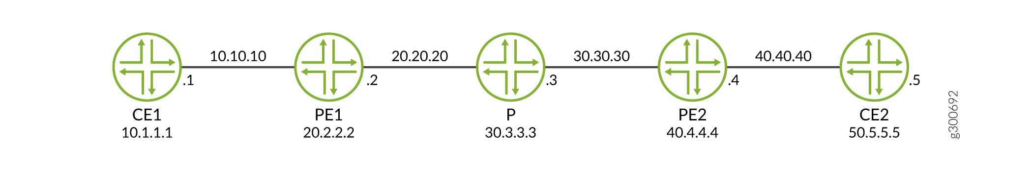
示例:在 cRPD 中为 MPLS 配置静态标签交换路径
此示例展示通过配置 BGP 和 MPLS 静态标签交换路径,VPN 流量如何通过 PE 之间的 v4 MPLS 隧道流动。
要求
此示例使用以下硬件和软件组件:
-
Ubuntu 软件版本 18.04
-
Linux 内核版本 4.5 或更高版本
-
cRPD 软件版本 19.4R1 或更高版本
在为 MPLS 转发配置静态 LSP 之前,必须安装以下基本组件:
-
在其上创建 cRPD 实例的主机作系统上的 MPLS 模块。有关详细信息,请参阅 在主机作系统上配置设置。
-
提供商边缘路由器 (PE1)、提供商路由器 (P) 和提供商边缘路由器 (PE2)。有关安装,请参阅 在 Docker 上安装 cRPD。
概述
在此示例中,PE1 充当 MPLS 网络的标签边缘路由器或入口节点,通过附加标签来封装数据包。P 充当标签交换路由器,使用 MPLS 网络中的标签传输 MPLS 数据包。
要配置 MPLS,必须先在入口和中转路由器上创建一个或多个命名路径。对于每个路径,您可以在路径中指定部分或全部中转路由器。
为 MPLS 配置静态标签交换路径 (LSP) 类似于在单个路由器上配置静态路由。
配置
要在 cRPD 上为 MPLS 配置静态 LSP,请执行以下作:
配置 PE1 路由器
分步过程
要配置静态 LSP,请执行以下作:
-
创建表 inet.0 和 mpls.0。
[edit routing-options] user@crpd1# set rib inet.0 user@crpd1# set rib mpls.0 user@crpd1# set router-id 20.2.2.2 -
配置 BGP 会话。
[edit protocols bgp group VPN] user@crpd1# set type internal local-address 20.2.2.2 family inet-vpn unicast user@crpd1# set local-as 5 user@crpd1# set neighbor 40.4.4.4 family inet-vpn unicast -
配置静态标签范围和入口静态 LSP 参数。
[edit protocols mpls] user@crpd1# set interface all user@crpd1# set label-range static-label-range 1000000 1048575 user@crpd1# set static-label-switched-path pe2 ingress install 40.4.4.4/32 active user@crpd1# set static-label-switched-path pe2 ingress to 40.4.4.4 next-hop 20.20.20.2 push 1000001 -
配置来自入口 PE2 的静态路由。
[edit routing-options static] user@crpd1# set route 20.2.2.2/32 next-hop 20.20.20.2 user@crpd1# set route 40.4.4.4/32 static-lsp-next-hop pe2 -
在 PE1 和其他路由实例参数上配置 VRF 路由实例。
[edit routing-instances vrfblue]
user@crpd1# set routing-options static route 10.1.1.1/32 next-hop 10.10.10.1
user@crpd1# set route-distinguisher 100:100
user@crpd1# set vrf-target target:100:100
user@crpd1# set interface all
结果
在配置模式下,在 PE1 上输入 show protocols bgp 和 run show configuration protocols mpls 命令,以确认您的配置。如果输出未显示预期的配置,请重复此示例中的配置说明,以便进行更正。
user@crpd1# show protocols bgp
group VPN {
    type internal;
    local-address 20.2.2.2;
    family inet-vpn {
        unicast;
    }
    local-as 5;
    neighbor 40.4.4.4 {
        family inet-vpn {
            unicast;
        }
    }
}
user@crpd1# run show configuration protocols mpls
interface all;
static-label-switched-path pe2 {
    ingress {
        next-hop 20.20.20.3;
        to 40.4.4.4;
        push 1000001;
    }
}
如果完成设备配置,请从配置模式进入提交。
配置提供商 P 路由器。
分步过程
要配置静态 LSP,请执行以下作:
-
配置路由器 P 的路由器 ID。
[edit routing-options] user@crpd2# set rib mpls.0 user@crpd2# set router-id 30.3.3.3 -
为交换和弹出标签配置传输静态 LSP。
[edit protocols mpls]
user@crpd2# set label-range static-label-range 1000000 1048575
user@crpd2# set static-label-switched-path pe2 transit 1000001 next-hop 30.30.30.4 swap 1000002
user@crpd2# set static-label-switched-path pe1 transit 1000003 next-hop 20.20.20.2 swap 1000004
user@crpd2# set static-label-switched-path pe2 transit 1000001 pop next-hop 30.30.30.4
user@crpd2# set static-label-switched-path pe1 transit 1000003 pop next-hop 20.20.20.2
结果
在配置模式下,在 P 上输入show protocols bgprun show configuration protocols mpls、 和run show mpls interface命令,以确认您的配置。如果输出未显示预期的配置,请重复此示例中的配置说明,以便进行更正。
user@crpd2# run show configuration protocols mpls
interface all;
static-label-switched-path pe1 {
    transit 1000003 {
        next-hop 20.20.20.2;
        swap 1000004;
    }
}
static-label-switched-path pe2 {
    transit 1000001 {
        next-hop 30.30.30.4;
        swap 1000002;
    }
}
如果完成设备配置,请从配置模式进入提交。
配置 PE2 路由器
分步过程
要在 PE2 上为 MPLS 配置静态 LSP,请执行以下作:
-
配置 BGP 会话。
[edit protocols bgp group VPN ] user@crpd3# set type internal local-address 40.4.4.4 family inet-vpn unicast user@crpd3# set local-as 5 user@crpd3# set neighbor 20.2.2.2 family inet-vpn unicast -
配置入口静态 LSP 参数。
[edit protocols mpls ] user@crpd3# set interface all user@crpd3# set label-range static-label-range 1000000 1048575 user@crpd3# set static-label-switched-path pe1 ingress install 20.2.2.2/32 active user@crpd3# set static-label-switched-path pe1 ingress to 20.2.2.2 next-hop 30.30.30.4 push 1000003 -
配置路由器 ID 和来自入口 PE1 的静态路由。
[edit routing-options] user@crpd3# set rib inet.0 user@crpd3# set router-id 40.4.4.4 user@crpd3# set static route 40.4.4.4/32 next-hop 30.30.30.4 user@crpd3# set static route 20.2.2.2/32 static-lsp-next-hop pe1 -
在 PE2 和其他路由实例参数上配置 VRF 路由实例。
[edit routing-instances vrfblue]
user@crpd3# set routing-options static route 50.5.5.5/32 next-hop 40.40.40.5
user@crpd3# set route-distinguisher 100:100
user@crpd3# set vrf-target target:100:100
user@crpd3# set interface all
结果
在配置模式下,在 PE2 上输入 run show configuration protocols mpls 和 run show mpls interface 命令,以确认您的配置。如果输出未显示预期的配置,请重复此示例中的配置说明,以便进行更正。
user@crpd3# show protocols bgp
group VPN {
    type internal;
    local-address 40.4.4.4;
    family inet-vpn {
        unicast;
    }
    local-as 5;
    neighbor 20.2.2.2 {
        family inet-vpn {
            unicast;
        }
    }
}
user@crpd3# run show configuration protocols mpls
interface all;
static-label-switched-path pe2 {
    ingress {
        next-hop 20.20.20.3;
        to 40.4.4.4;
        push 1000001;
    }
}
如果完成设备配置,请从配置模式进入提交。
验证
验证 PE1 上的 MPLS 转发
目的
验证 PE1 上的 MPLS 配置。
行动
在作模式下,输入 show route table vrfblue.inet.0 50.5.5.5 命令:
user@crpd1> show route table vrfblue.inet.0 50.5.5.5
vrfblue.inet.0: 5 destinations, 5 routes (5 active, 0 holddown, 0 hidden)
+ = Active Route, - = Last Active, * = Both

50.5.5.5/32         *[BGP/170] 00:01:03, localpref 100, from 40.4.4.4
                      AS path: I, validation-state: unverified
                    >  to 20.20.20.3 via pe1-p, Push 299776, Push 1000001(top)
在作模式下,输入 show mpls label usage 命令:
user@crpd1> show mpls label usage
Label space Total   Available        Applications
LSI         999984  999983 (100.00%) BGP/LDP VPLS with no-tunnel-services, BGP L3VPN with vrf-table-label
Block       999984  999983 (100.00%) BGP/LDP VPLS with tunnel-services, BGP L2VPN
Dynamic     999984  999983 (100.00%) RSVP, LDP, PW, L3VPN, RSVP-P2MP, LDP-P2MP, MVPN, EVPN, BGP
Static      48576   48576  (100.00%) Static LSP, Static PW
Effective Ranges
Range name  Shared with Start   End
Dynamic     16      999999
Static      1000000 1048575
Configured Ranges
Range name  Shared with Start   End
Dynamic     16      999999
Static      1000000 1048575
在作模式下,输入 show mpls static-lsp 命令:
user@crpd1> show mpls static-lsp
Ingress LSPs:
LSPname                             To              State
pe2                                 40.4.4.4         Up
Total 1, displayed 1, Up 1, Down 0

Transit LSPs:
Total 0, displayed 0, Up 0, Down 0

Bypass LSPs:
Total 0, displayed 0, Up 0, Down 0

Segment LSPs:
Total 0, displayed 0, Up 0, Down 0
在作模式下,输入 show route table inet.3 命令:
user@crpd1> show route table inet.3
inet.3: 1 destinations, 1 routes (1 active, 0 holddown, 0 hidden)
+ = Active Route, - = Last Active, * = Both

40.4.4.4/32         *[MPLS/6/1] 00:04:44, metric 0
                    >  to 20.20.20.3 via pe1-p, Push 1000001
在作模式下,输入 show route table mpls.0 命令:
user@crpd1> show route table mpls.0
mpls.0: 6 destinations, 6 routes (6 active, 0 holddown, 0 hidden)
+ = Active Route, - = Last Active, * = Both

0                  *[MPLS/0] 00:15:45, metric 1
                       Receive
1                  *[MPLS/0] 00:15:45, metric 1
                       Receive
2                  *[MPLS/0] 00:15:45, metric 1
                       Receive
13                 *[MPLS/0] 00:15:45, metric 1
                       Receive
299776             *[VPN/170] 00:06:32
                    >  to 10.10.10.1 via pe1-ce1, Pop
299776(S=0)        *[VPN/170] 00:06:32
                    >  to 10.10.10.1 via pe1-ce1, Pop
在作模式下,输入 ip route list table 5 50.5.5.5 命令:
user@crpd1> ip route list table 5 50.5.5.5
50.5.5.5 encap mpls 1000001/299776 via 20.20.20.3 dev pe1-p proto 22
在作模式下,输入 ip -f mpls route 命令:
user@crpd1> ip -f mpls route
299776 via inet 10.10.10.1 dev pe1-ce1 proto 22
验证 P 上的 MPLS 转发
目的
验证 P 上的 MPLS 配置。
行动
在 shell 模式下,输入 show route table mpls.0 命令:
user@crpd2> show route table mpls.0
mpls.0: 10 destinations, 10 routes (10 active, 0 holddown, 0 hidden)
+ = Active Route, - = Last Active, * = Both

0                  *[MPLS/0] 00:00:11, metric 1
                       Receive
1                  *[MPLS/0] 00:00:11, metric 1
                       Receive
2                  *[MPLS/0] 00:00:11, metric 1
                       Receive
13                 *[MPLS/0] 00:00:11, metric 1
                       Receive
299776             *[VPN/170] 00:00:05
                    >  to 20.20.20.2 via p-pe1, Pop
299776(S=0)        *[VPN/170] 00:00:05
                    >  to 20.20.20.2 via p-pe1, Pop
299792             *[VPN/170] 00:00:05
                    >  to 30.30.30.4 via p-pe2, Pop
299792(S=0)        *[VPN/170] 00:00:05
                    >  to 30.30.30.4 via p-pe2, Pop
1000001            *[MPLS/6] 00:00:11, metric 1
                    >  to 30.30.30.4 via p-pe2, Swap 1000002
1000003            *[MPLS/6] 00:00:11, metric 1
                    >  to 20.20.20.2 via p-pe1, Swap 1000004
user@crpd2> show mpls static-lsp
Ingress LSPs:
Total 0, displayed 0, Up 0, Down 0

Transit LSPs:
LSPname                             Incoming-label  State
pe1                                 1000003         Up
pe2                                 1000001         Up
Total 2, displayed 2, Up 2, Down 0

Bypass LSPs:
Total 0, displayed 0, Up 0, Down 0

Segment LSPs:
Total 0, displayed 0, Up 0, Down 0
在 bash shell 模式下,输入 ip -f mpls route 命令:
user@crpd2:/# ip -f mpls route
299776 via inet 20.20.20.2 dev p-pe1 proto 22
299792 via inet 30.30.30.4 dev p-pe2 proto 22
1000001 as to 1000002 via inet 30.30.30.4 dev p-pe2 proto 22
1000003 as to 1000004 via inet 20.20.20.2 dev p-pe1 proto 22
验证 PE2 上的 MPLS 转发
目的
验证 P 上的 MPLS 配置。
行动
在 shell 模式下,输入 show route table vrfblue.inet.0 10.1.1.1 命令:
user@crpd3> show route table vrfblue.inet.0 10.1.1.1
vrfblue.inet.0: 5 destinations, 5 routes (5 active, 0 holddown, 0 hidden)
+ = Active Route, - = Last Active, * = Both

10.1.1.1/32         *[BGP/170] 00:03:00, localpref 100, from 2.2.2.2
                      AS path: I, validation-state: unverified
                    >  to 30.30.30.3 via pe2-p, Push 299776, Push 1000003(top)
user@crpd3> show mpls static-lsp
Ingress LSPs:
LSPname                             To              State
pe1                                 20.2.2.2         Up
Total 1, displayed 1, Up 1, Down 0

Transit LSPs:
LSPname                             Incoming-label  State
pe2                                 1000002         Dn
Total 1, displayed 1, Up 0, Down 1

Bypass LSPs:
Total 0, displayed 0, Up 0, Down 0

Segment LSPs:
Total 0, displayed 0, Up 0, Down 0
user@crpd3> show route table mpls.0
mpls.0: 6 destinations, 6 routes (6 active, 0 holddown, 0 hidden)
+ = Active Route, - = Last Active, * = Both

0                  *[MPLS/0] 00:17:31, metric 1
                       Receive
1                  *[MPLS/0] 00:17:31, metric 1
                       Receive
2                  *[MPLS/0] 00:17:31, metric 1
                       Receive
13                 *[MPLS/0] 00:17:31, metric 1
                       Receive
299776             *[VPN/170] 00:03:07
                    >  to 40.40.40.5 via pe2-ce2, Pop
299776(S=0)        *[VPN/170] 00:03:07
                    >  to 40.40.40.5 via pe2-ce2, Pop
在 bash shell 模式下,输入 ip -f mpls route 命令:
user@crpd3:/# ip -f mpls route
299776 via inet 40.40.40.5 dev pe2-ce2 proto 22
在 bash shell 模式下,输入 ip route list table 5 10.1.1.1 命令:
user@crpd3:/# ip route list table 5 10.1.1.1
10.1.1.1 encap mpls 1000003/299776 via 30.30.30.3 dev pe2-p proto 22
意义
您可以验证所有设备上 PE 之间的静态 LSP 是否已开启,并且路由是否填充在相应的路由表 inet.o 和 inet.3 Linux FIB 中。