NESTA PÁGINA
Exemplo: Configuração da agregação de enlaces multichassis na Série QFX
Exemplo: Configuração da agregação de enlaces multichassis na Série MX
Exemplo: configure recursos opcionais para agregação de enlaces multichassis
Exemplo: configuração de CoS para tráfego de switches de trânsito FCoE em um MC-LAG
Exemplos de MC-LAG
Exemplo: Configuração da agregação de enlaces multichassis na Série QFX
Nossa equipe de testes de conteúdo validou e atualizou este exemplo.
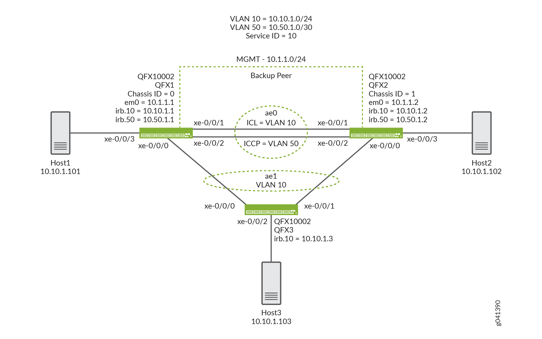
Este exemplo mostra como grupos de agregação de enlaces multichassis (MC-LAGs) permitem que um dispositivo cliente forme uma interface lag lógica entre dois switches para fornecer redundância e balanceamento de carga entre os dois switches, suporte multihoming e uma rede de Camada 2 sem loop sem executar o Spanning Tree Protocol (STP).
Requisitos
Este exemplo usa os seguintes componentes de hardware e software:
Versão Junos OS 13.2X51-D10 ou posterior para o QFX5100 switches autônomos, versão 15.1X53-D10 ou posteriores para QFX10002 switches autônomos.
Revalidado no Junos OS Release 17.3R1 para switches de QFX5100 e QFX10000.
Revalidado no Junos OS Release 19.4R1 para switches QFX10000.
Antes de configurar um MC-LAG, certifique-se de entender como:
Configure interfaces Ethernet agregadas em um switch. Veja exemplo: configuração da agregação de enlaces entre um produto da Série QFX e um switch de agregação.
Configure o Link Aggregation Control Protocol (LACP) em interfaces Ethernet agregadas em um switch. Veja exemplo: configuração da agregação de enlaces com LACP entre um produto da Série QFX e um switch de agregação.
Visão geral
Neste exemplo, você configura um MC-LAG em dois switches, consistindo em duas interfaces Ethernet agregadas, um link de proteção de enlace de controle de interchasse (ICL-PL), link de proteção multichassis para o ICL-PL, o protocolo de controle entre chassis para os pares que hospedam o MC-LAG e conectividade de Camada 3 entre os pares MC-LAG. A conectividade de camada 3 é necessária para o ICCP.
Topologia
A topologia usada neste exemplo consiste em dois switches hospedando um MC-LAG. Os dois switches estão conectados a um servidor. A Figura 1 mostra a topologia usada neste exemplo.
Configuração
Configuração rápida da CLI
Para configurar rapidamente este exemplo, copie os seguintes comandos, cole-os em um arquivo de texto, remova quaisquer quebras de linha, altere todos os detalhes necessários para combinar com a configuração da sua rede, copiar e colar os comandos na CLI no nível de [edit] hierarquia e, em seguida, entrar no commit modo de configuração.
QFX1
set chassis aggregated-devices ethernet device-count 2
set interfaces xe-0/0/0 ether-options 802.3ad ae1
set interfaces xe-0/0/1 ether-options 802.3ad ae0
set interfaces xe-0/0/2 ether-options 802.3ad ae0
set interfaces xe-0/0/3 unit 0 family ethernet-switching interface-mode access
set interfaces xe-0/0/3 unit 0 family ethernet-switching vlan members v10
set interfaces ae0 aggregated-ether-options lacp active
set interfaces ae0 unit 0 family ethernet-switching interface-mode trunk
set interfaces ae0 unit 0 family ethernet-switching vlan members v50
set interfaces ae0 unit 0 family ethernet-switching vlan members v10
set interfaces ae1 aggregated-ether-options lacp active
set interfaces ae1 aggregated-ether-options lacp system-id 00:01:02:03:04:05
set interfaces ae1 aggregated-ether-options lacp admin-key 3
set interfaces ae1 aggregated-ether-options mc-ae mc-ae-id 3
set interfaces ae1 aggregated-ether-options mc-ae redundancy-group 1
set interfaces ae1 aggregated-ether-options mc-ae chassis-id 0
set interfaces ae1 aggregated-ether-options mc-ae mode active-active
set interfaces ae1 aggregated-ether-options mc-ae status-control active
set interfaces ae1 aggregated-ether-options mc-ae init-delay-time 240
set interfaces ae1 unit 0 family ethernet-switching interface-mode trunk
set interfaces ae1 unit 0 family ethernet-switching vlan members v10
set interfaces em0 unit 0 family inet address 10.1.1.1/24
set interfaces irb unit 10 family inet address 10.10.1.1/24
set interfaces irb unit 50 family inet address 10.50.1.1/30
set multi-chassis multi-chassis-protection 10.50.1.2 interface ae0
set protocols iccp local-ip-addr 10.50.1.1
set protocols iccp peer 10.50.1.2 session-establishment-hold-time 340
set protocols iccp peer 10.50.1.2 redundancy-group-id-list 1
set protocols iccp peer 10.50.1.2 backup-liveness-detection backup-peer-ip 10.1.1.2
set protocols iccp peer 10.50.1.2 liveness-detection minimum-receive-interval 1000
set protocols iccp peer 10.50.1.2 liveness-detection transmit-interval minimum-interval 1000
set switch-options service-id 10
set vlans v10 vlan-id 10
set vlans v10 l3-interface irb.10
set vlans v50 vlan-id 50
set vlans v50 l3-interface irb.50
QFX2
set chassis aggregated-devices ethernet device-count 2
set interfaces xe-0/0/0 ether-options 802.3ad ae1
set interfaces xe-0/0/1 ether-options 802.3ad ae0
set interfaces xe-0/0/2 ether-options 802.3ad ae0
set interfaces xe-0/0/3 unit 0 family ethernet-switching interface-mode access
set interfaces xe-0/0/3 unit 0 family ethernet-switching vlan members v10
set interfaces ae0 aggregated-ether-options lacp active
set interfaces ae0 unit 0 family ethernet-switching interface-mode trunk
set interfaces ae0 unit 0 family ethernet-switching vlan members v50
set interfaces ae0 unit 0 family ethernet-switching vlan members v10
set interfaces ae1 aggregated-ether-options lacp active
set interfaces ae1 aggregated-ether-options lacp system-id 00:01:02:03:04:05
set interfaces ae1 aggregated-ether-options lacp admin-key 3
set interfaces ae1 aggregated-ether-options mc-ae mc-ae-id 3
set interfaces ae1 aggregated-ether-options mc-ae redundancy-group 1
set interfaces ae1 aggregated-ether-options mc-ae chassis-id 1
set interfaces ae1 aggregated-ether-options mc-ae mode active-active
set interfaces ae1 aggregated-ether-options mc-ae status-control standby
set interfaces ae1 aggregated-ether-options mc-ae init-delay-time 240
set interfaces ae1 unit 0 family ethernet-switching interface-mode trunk
set interfaces ae1 unit 0 family ethernet-switching vlan members v10
set interfaces em0 unit 0 family inet address 10.1.1.2/24
set interfaces irb unit 10 family inet address 10.10.1.2/24
set interfaces irb unit 50 family inet address 10.50.1.2/30
set multi-chassis multi-chassis-protection 10.50.1.1 interface ae0
set protocols iccp local-ip-addr 10.50.1.2
set protocols iccp peer 10.50.1.1 session-establishment-hold-time 340
set protocols iccp peer 10.50.1.1 redundancy-group-id-list 1
set protocols iccp peer 10.50.1.1 backup-liveness-detection backup-peer-ip 10.1.1.1
set protocols iccp peer 10.50.1.1 liveness-detection minimum-receive-interval 1000
set protocols iccp peer 10.50.1.1 liveness-detection transmit-interval minimum-interval 1000
set switch-options service-id 10
set vlans v10 vlan-id 10
set vlans v10 l3-interface irb.10
set vlans v50 vlan-id 50
set vlans v50 l3-interface irb.50
QFX3
set chassis aggregated-devices ethernet device-count 2
set interfaces xe-0/0/0 ether-options 802.3ad ae1
set interfaces xe-0/0/1 ether-options 802.3ad ae1
set interfaces xe-0/0/2 unit 0 family ethernet-switching interface-mode access
set interfaces xe-0/0/2 unit 0 family ethernet-switching vlan members v10
set interfaces ae1 aggregated-ether-options lacp active
set interfaces ae1 unit 0 family ethernet-switching interface-mode trunk
set interfaces ae1 unit 0 family ethernet-switching vlan members v10
set interfaces em0 unit 0 family inet address 10.1.1.3/24
set interfaces irb unit 10 family inet address 10.10.1.3/24
set vlans v10 vlan-id 10
set vlans v10 l3-interface irb.10
Configuração do MC-LAG em dois switches
Procedimento passo a passo
O exemplo a seguir exige que você navegue por vários níveis na hierarquia de configuração. Para obter informações sobre como navegar na CLI, consulte Usando o Editor de CLI no modo de configuração.
Para habilitar interfaces e link de proteção multichassis entre os pares MC-LAG:
Configure o número de LAGs tanto no QFX1 quanto no QFX2.
[edit chassis]
user@switch# set aggregated-devices ethernet device-count 2
Adicione interfaces de membros às interfaces Ethernet agregadas tanto no QFX1 quanto no QFX2.
QFX1 and QFX2:
[edit interfaces]
user@switch# set xe-0/0/0 ether-options 802.3ad ae1
[edit interfaces]
user@switch# set xe-0/0/1 ether-options 802.3ad ae0
[edit interfaces]
user@switch# set xe-0/0/2 ether-options 802.3ad ae0
Configure uma interface de acesso para o host final conectado.
[edit interfaces]
user@switch# set xe-0/0/3 unit 0 family ethernet-switching interface-mode access
Adicione interfaces de membros ao VLAN v10.
[edit interfaces]
user@switch# set interfaces xe-0/0/3 unit 0 family ethernet-switching vlan members v10
Configure uma interface de tronco entre QFX1 e QFX2.
[edit interfaces]
user@switch# set ae0 unit 0 family ethernet-switching interface-mode trunk
Habilite VLANs no MC-LAG entre o QFX1 e o QFX2.
[edit]
user@switch# set vlans v10 vlan-id 10
[edit]
user@switch# set vlans v50 vlan-id 50
[edit interfaces]
user@switch# set ae0 unit 0 family ethernet-switching vlan members v10
[edit interfaces]
user@switch# set ae0 unit 0 family ethernet-switching vlan members v50
Configure um IRB 50.
[edit irb]
user@switch# set irb.50
Atribua o VLAN 50 à irb.50.
[edit]
user@switch# set vlans v50 l3-interface irb.50
Configure um IRB 10.
[edit irb]
user@switch# set irb.10
Atribua VLAN 10 irb.10.
[edit]
user@switch# set vlans v10 l3-interface irb.10
Habilite o LACP na interface MC-LAG no QFX1 e QFX2.
Nota:Pelo menos uma ponta precisa estar ativa. A outra ponta pode ser ativa ou passiva.
[edit interfaces]
user@switch# set ae0 aggregated-ether-options lacp active

[edit interfaces]
user@switch# set ae1 aggregated-ether-options lacp active
Especifique o mesmo ID do sistema LACP para o MC-LAG no QFX1 e QFX2.
[edit interfaces]
user@switch# set ae1 aggregated-ether-options lacp system-ID 00:01:02:03:04:05
Especifique a mesma chave de administração LACP tanto no QFX1 quanto no QFX2.
[edit interfaces]
user@switch# set ae1 aggregated-ether-options lacp admin-key 3
Especifique o mesmo número agregado de identificação de Ethernet em ambos os pares MC-LAG no QFX1 e QFX2.
[edit interfaces]
user@switch# set ae1 aggregated-ether-options mc-ae mc-ae-id 3
Especifique um ID de chassi exclusivo para o MC-LAG nos pares MC-LAG no QFX1 e QFX2.
QFX1:
[edit interfaces]
user@switch# set ae1 aggregated-ether-options mc-ae chassis-id 0
QFX2:
[edit interfaces]
user@switch# set ae1 aggregated-ether-options mc-ae chassis-id 1
Especifique o modo de operação do MC-LAG tanto no QFX1 quanto no QFX2.
Nota:O único modo ativo-ativo é suportado neste momento.
[edit interfaces]
user@switch# set ae1 aggregated-ether-options mc-ae mode active-active
Especifique o controle de status para MC-LAG no QFX1 e QFX2.
Nota:Você deve configurar o controle de status tanto no QFX1 quanto no QFX2 hospedando o MC-LAG. Se um peer estiver no modo ativo, o outro deve estar no modo de espera.
QFX1:
[edit interfaces]
user@switch# set ae1 aggregated-ether-options mc-ae status-control active
QFX2:
[edit interfaces]
user@switch# set ae1 aggregated-ether-options mc-ae status-control standby
Especifique o número de segundos pelos quais a criação da interface Ethernet agregada por multichassis deve ser adiada após a reinicialização do QFX1 e do QFX2.
Nota:O valor recomendado para a configuração máxima de VLAN (por exemplo, 4.000 VLANS) é de 240 segundos. Se a espionagem IGMP estiver habilitada em todas as VLANs, o valor recomendado é de 420 segundos.
[edit interfaces]
user@switch# set ae1 aggregated-ether-options mc-ae init-delay-time 240
Configure a conectividade de Camada 3 entre os pares MC-LAG tanto no QFX1 quanto no QFX2.
[edit vlans]
user@switch# set v50 vlan-id 50
[edit vlans]
user@switch# set v50 l3-interface irb.50
[edit interfaces]
user@switch# set ae0 unit 0 family ethernet-switching interface-mode trunk vlan members v50
Configure um link de proteção multichassis entre o QFX1 e o QFX2.
QFX1:
[edit]
user@switch# set multi-chassis multi-chassis-protection 10.50.1.2 interface ae0
QFX2:
[edit]
user@switch# set multi-chassis multi-chassis-protection 10.50.1.1 interface ae0
Configure o endereço IP local para estar na conexão ICCP no QFX1 e QFX2.
QFX1:
[edit protocols]
user@switch# set iccp local-ip-addr 10.50.1.1
QFX2:
[edit protocols]
user@switch# set iccp local-ip-addr 10.50.1.2
(Opcional) Configure o tempo durante o qual uma conexão ICCP deve ter sucesso entre os pares MC-LAG no QFX1 e QFX2.
Nota:Nos switches da Série QFX, o tempo de espera padrão do estabelecimento de sessão é de 300 segundos. No entanto, o tempo de estabelecimento da sessão deve ser pelo menos 100 segundos maior do que o tempo de atraso init. Você pode atualizar opcionalmente o tempo de estabelecimento da sessão para 340 segundos e o tempo de atraso de init de 240 segundos.
QFX1:
[edit protocols]
user@switch# set iccp peer 10.50.1.2 session-establishment-hold-time 340
QFX2:
[edit protocols]
user@switch# set iccp peer 10.50.1.1 session-establishment-hold-time 340
Configure os grupos de redundância para o ICCP no QFX1 e QFX2.
QFX1:
[edit protocols]
user@switch# set iccp peer 10.50.1.2 redundancy-group-id-list 1
QFX2:
[edit protocols]
user@switch# set iccp peer 10.50.1.1 redundancy-group-id-list 1
(Opcional) Configure o endereço IP de backup a ser usado para detecção de liveness de backup tanto no QFX1 quanto no QFX2.
Nota:Por padrão, a detecção de liveness do backup não está habilitada. Configurar um endereço IP de backup ajuda a obter perda de tráfego abaixo de um segundo durante uma reinicialização de peer MC-LAG.
QFX1:
[edit protocols]
user@switch# set iccp peer 10.50.1.2 backup-liveness-detection backup-peer-ip 10.1.1.2
QFX2:
[edit protocols]
user@switch# set iccp peer 10.50.1.1 backup-liveness-detection backup-peer-ip 10.1.1.1
Configure o endereço IP peer e o intervalo mínimo de recebimento para uma sessão de BFD para ICCP no QFX1 e QFX2.
QFX1:
[edit protocols]
user@switch# set iccp peer 10.50.1.2 liveness-detection minimum-receive-interval 1000
QFX2:
[edit protocols]
user@switch# set iccp peer 10.50.1.1 liveness-detection minimum-receive-interval 1000
Configure o endereço IP peer e o intervalo mínimo de transmissão para sessão de BFD para ICCP no QFX1 e QFX2.
QFX1:
[edit protocols]
user@switch# set iccp peer 10.50.1.2 liveness-detection transmit-interval minimum-interval 1000
QFX2:
[edit protocols]
user@switch# set iccp peer 10.50.1.1 liveness-detection transmit-interval minimum-interval 1000
Para habilitar o ID de serviço no QFX1 e QFX2:
O ID do serviço de switch é usado para sincronizar aplicativos, IGMP, ARP e mac learning entre membros mc-LAG.
[edit switch-options]
user@switch# set service-id 10
Resultados
Aqui estão os resultados de sua configuração no QFX1.
chassis {
    aggregated-devices {
        ethernet {
            device-count 2;
        }
    }
}
interfaces {
    xe-0/0/0 {
        ether-options {
            802.3ad ae1;
        }
    }
    xe-0/0/1 {
        ether-options {
            802.3ad ae0;
        }
    }
    xe-0/0/2 {
        ether-options {
            802.3ad ae0;
        }
    }
    xe-0/0/3 {
        unit 0 {
            family ethernet-switching {
                interface-mode access;
                vlan {
                    members v10;
                }
            }
        }
    }
    ae0 {
        aggregated-ether-options {
            lacp {
                active;
            }
        }
        unit 0 {
            family ethernet-switching {
                interface-mode trunk;
                vlan {
                    members [ v50 v10 ];
                }
            }
        }
    }
    ae1 {
        aggregated-ether-options {
            lacp {
                active;
                system-id 00:01:02:03:04:05;
                admin-key 3;
            }
            mc-ae {
                mc-ae-id 3;
                redundancy-group 1;
                chassis-id 0;
                mode active-active;
                status-control active;
                init-delay-time 240;
            }
        }
        unit 0 {
            family ethernet-switching {
                interface-mode trunk;
                vlan {
                    members v10;
                }
            }
        }
    }
    em0 {
        unit 0 {
            family inet {
                address 10.1.1.1/24;
            }
        }
    }
    irb {
        unit 10 {
            family inet {
                address 10.10.1.1/24;
            }
        }
        unit 50 {
            family inet {
                address 10.50.1.1/30;
            }
        }
    }
}
multi-chassis {
    multi-chassis-protection 10.50.1.2 {
        interface ae0;
    }
}
protocols {
    iccp {
        local-ip-addr 10.50.1.1;
        peer 10.50.1.2 {
            session-establishment-hold-time 340;
            redundancy-group-id-list 1;
            backup-liveness-detection {
                backup-peer-ip 10.1.1.2;
            }
            liveness-detection {
                minimum-receive-interval 1000;
                transmit-interval {
                    minimum-interval 1000;
                }
            }
        }
    }
}
switch-options {
    service-id 10;
}
vlans {
    v10 {
        vlan-id 10;
        l3-interface irb.10;
    }
    v50 {
        vlan-id 50;
        l3-interface irb.50;
    }
}
Exibir os resultados da configuração no QFX2.
chassis {
    aggregated-devices {
        ethernet {
            device-count 2;
        }
    }
}
interfaces {
    xe-0/0/0 {
        ether-options {
            802.3ad ae1;
        }
    }
    xe-0/0/1 {
        ether-options {
            802.3ad ae0;
        }
    }
    xe-0/0/2 {
        ether-options {
            802.3ad ae0;
        }
    }
    xe-0/0/3 {
        unit 0 {
            family ethernet-switching {
                interface-mode access;
                vlan {
                    members v10;
                }
            }
        }
    }
    ae0 {
        aggregated-ether-options {
            lacp {
                active;
            }
        }
        unit 0 {
            family ethernet-switching {
                interface-mode trunk;
                vlan {
                    members [ v50 v10 ];
                }
            }
        }
    }
    ae1 {
        aggregated-ether-options {
            lacp {
                active;
                system-id 00:01:02:03:04:05;
                admin-key 3;
            }
            mc-ae {
                mc-ae-id 3;
                redundancy-group 1;
                chassis-id 1;
                mode active-active;
                status-control standby;
                init-delay-time 240;
            }
        }
        unit 0 {
            family ethernet-switching {
                interface-mode trunk;
                vlan {
                    members v10;
                }
            }
        }
    }
    em0 {
        unit 0 {
            family inet {
                address 10.1.1.2/24;
            }
        }
    }
    irb {
        unit 10 {
            family inet {
                address 10.10.1.2/24;
            }
        }
        unit 50 {
            family inet {
                address 10.50.1.2/30;
            }
        }
    }
}
multi-chassis {
    multi-chassis-protection 10.50.1.1 {
        interface ae0;
    }
}
protocols {
    iccp {
        local-ip-addr 10.50.1.2;
        peer 10.50.1.1 {
            session-establishment-hold-time 340;
            redundancy-group-id-list 1;
            backup-liveness-detection {
                backup-peer-ip 10.1.1.1;
            }
            liveness-detection {
                minimum-receive-interval 1000;
                transmit-interval {
                    minimum-interval 1000;
                }
            }
        }
    }
}
switch-options {
    service-id 10;
}
vlans {
    v10 {
        vlan-id 10;
        l3-interface irb.10;
    }
    v50 {
        vlan-id 50;
        l3-interface irb.50;
    }
}
Exibir os resultados da configuração no QFX3.
chassis {
    aggregated-devices {
        ethernet {
            device-count 2;
        }
    }
}
interfaces {
    xe-0/0/0 {
        ether-options {
            802.3ad ae1;
        }
    }
    xe-0/0/1 {
        ether-options {
            802.3ad ae1;
        }
    }
    xe-0/0/2 {
        unit 0 {
            family ethernet-switching {
                interface-mode access;
                vlan {
                    members v10;
                }
            }
        }
    }
    ae1 {
        aggregated-ether-options {
            lacp {
                active;
            }
        }
        unit 0 {
            family ethernet-switching {
                interface-mode trunk;
                vlan {
                    members v10;
                }
            }
        }
    }
    em0 {
        unit 0 {
            family inet {
                address 10.1.1.3/24;
            }
        }
    }
    irb {
        unit 10 {
            family inet {
                address 10.10.1.3/24;
            }
        }
    }
}
vlans {
    v10 {
        vlan-id 10;
        l3-interface irb.10;
    }
}
Verificação
Verifique se a configuração está funcionando corretamente.
- Verificando se o ICCP está trabalhando no QFX1
- Verificando se o LACP está ativo no QFX1
- Verificando se as interfaces MC-AE e ICL-PL estão ativas no QFX1
- Verificando se o aprendizado MAC está ocorrendo no QFX1
- Verificar se o Host1 pode se conectar ao host2
Verificando se o ICCP está trabalhando no QFX1
Propósito
Verifique se o ICCP está sendo executado no QFX1.
Ação
user@switch> show iccp
Redundancy Group Information for peer 10.50.1.2
  TCP Connection       : Established
  Liveliness Detection : Up
  Backup liveness peer status: Up
  Redundancy Group ID          Status
    1                           Up

Client Application: lacpd
  Redundancy Group IDs Joined: 1

Client Application: l2ald_iccpd_client
  Redundancy Group IDs Joined: 1
Significado
Essa saída mostra que a conexão TCP entre os pares que hospedam o MC-LAG está ativa, a detecção de liveness está ativa e os aplicativos de clientes MCSNOOPD e ESWD estão sendo executados.
Verificando se o LACP está ativo no QFX1
Propósito
Verifique se o LACP está ativo no QFX1.
Ação
user@switch> show lacp interfaces
Aggregated interface: ae0
    LACP state:       Role   Exp   Def  Dist  Col  Syn  Aggr  Timeout  Activity
      xe-0/0/1       Actor    No    No   Yes  Yes  Yes   Yes     Fast    Active
      xe-0/0/1     Partner    No    No   Yes  Yes  Yes   Yes     Fast    Active
      xe-0/0/2       Actor    No    No   Yes  Yes  Yes   Yes     Fast    Active
      xe-0/0/2     Partner    No    No   Yes  Yes  Yes   Yes     Fast    Active
    LACP protocol:        Receive State  Transmit State          Mux State
      xe-0/0/1                  Current   Fast periodic Collecting distributing
      xe-0/0/2                  Current   Fast periodic Collecting distributing

Aggregated interface: ae1
    LACP state:       Role   Exp   Def  Dist  Col  Syn  Aggr  Timeout  Activity
      xe-0/0/0       Actor    No    No   Yes  Yes  Yes   Yes     Fast    Active
      xe-0/0/0     Partner    No    No   Yes  Yes  Yes   Yes     Fast    Active
    LACP protocol:        Receive State  Transmit State          Mux State
      xe-0/0/0                  Current   Fast periodic Collecting distributing
Significado
Essa saída mostra que o QFX1 está participando da negociação do LACP.
Verificando se as interfaces MC-AE e ICL-PL estão ativas no QFX1
Propósito
Verifique se as interfaces MC-AE e ICL-PL estão ativas no QFX1.
Ação
user@switch> show interfaces mc-ae
 Member Link                  : ae1
 Current State Machine's State: mcae active state
 Local Status                 : active
 Local State                  : up
 Peer Status                  : active
 Peer State                   : up
     Logical Interface        : ae1.0
     Topology Type            : bridge
     Local State              : up
     Peer State               : up
     Peer Ip/MCP/State        : 10.50.1.2 ae0.0 up
Significado
Essa saída mostra que a interface MC-AE no QFX1 está ativa.
Verificando se o aprendizado MAC está ocorrendo no QFX1
Propósito
Verifique se o aprendizado MAC está funcionando no QFX1.
Ação
user@switch> show ethernet-switching table
MAC flags (S - static MAC, D - dynamic MAC, L - locally learned, P - Persistent static, C - Control MAC
           SE - statistics enabled, NM - non configured MAC, R - remote PE MAC, O - ovsdb MAC)


Ethernet switching table : 3 entries, 3 learned
Routing instance : default-switch
    Vlan                MAC                 MAC         Age    Logical                NH        RTR
    name                address             flags              interface              Index     ID
    v10                 00:50:56:93:73:cd   DR            -   ae0.0                  0         0
    v10                 00:50:56:93:87:58   DL            -   xe-0/0/3.0             0         0
    v10                 00:50:56:93:89:a0   DLR           -   ae1.0                  0         0
Significado
A saída mostra três entradas de endereço MAC aprendidas.
Verificar se o Host1 pode se conectar ao host2
Propósito
Verifique se o Host1 pode ping Host2.
Ação
[edit]
user@HOST1> ping 10.10.1.102
PING 10.10.1.102 (10.10.1.102): 56 data bytes
64 bytes from 10.10.1.102: icmp_seq=0 ttl=64 time=157.788 ms
64 bytes from 10.10.1.102: icmp_seq=1 ttl=64 time=153.965 ms
64 bytes from 10.10.1.102: icmp_seq=2 ttl=64 time=102.126 ms
...
Significado
A saída mostra que o HOST1 pode pingar HOST2 com sucesso.
Solucionando problemas
Resolução de problemas de um LAG que está desativado
Problema
O show interfaces terse comando mostra que o MC-LAG é down.
Solução
Confira a seguir:
Verifique se não há incompatibilidade de configuração.
Verifique se todas as portas dos membros estão ativas.
Verifique se o MC-LAG faz parte da comutação Ethernet da família (Camada 2 LAG).
Verifique se o membro MC-LAG está conectado ao membro MC-LAG correto do outro lado.
Exemplo: Configuração da agregação de enlaces multichassis na Série MX
Este exemplo mostra como configurar um grupo de agregação de enlaces multichassis (MC-LAG) em um cenário ativo, que equilibra o tráfego entre os PEs.
- Requisitos
- Visão geral
- Configuração dos roteadores PE
- Configuração do dispositivo CE
- Configuração do roteador provedor
- Verificação
Requisitos
Este exemplo usa os seguintes componentes de hardware e software:
Este exemplo também se aplica a switches de QFX10002 e QFX10008.
Quatro roteadores da Série MX da Juniper Networks (MX240, MX480, MX960)
Junos OS Release 11.2 ou posterior em execução nos quatro roteadores
Visão geral
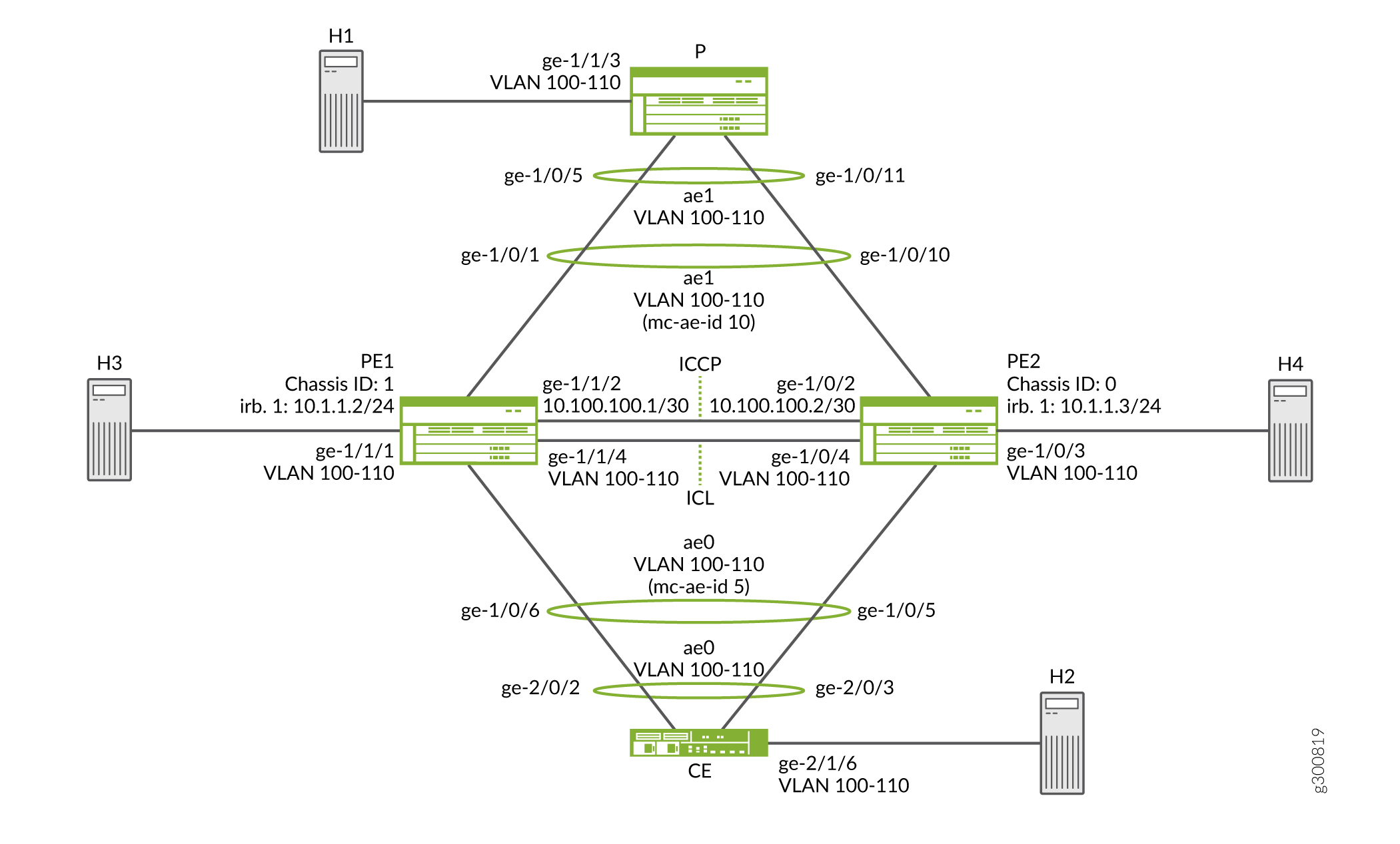
Considere uma topologia de amostra em que um roteador de borda do cliente, CE, está conectado a dois roteadores de borda (PE), PE1 e PE2, respectivamente. Os dois dispositivos PE têm um grupo de agregação de enlaces (LAG) conectado ao dispositivo CE. O modo configurado é ativo-ativo, o que significa que ambas as portas LAG dos roteadores PE estão ativas e transportando tráfego ao mesmo tempo. PE1 e PE2 estão conectados a um único roteador de provedor de serviços, P.
Neste exemplo, o roteador CE não está ciente de que seus links Ethernet agregados estão conectados a dois dispositivos PE separados. Os dois dispositivos PE têm um LAG conectado ao dispositivo CE. O modo configurado é ativo, o que significa que ambas as portas LAG dos roteadores PE estão ativas e transportando tráfego ao mesmo tempo.
Na Figura 2, da perspectiva do Roteador CE, todas as quatro portas pertencentes a um LAG estão conectadas a um único dispositivo de provedor de serviços. Como o modo configurado é ativo, todas as quatro portas estão ativas, e o dispositivo CE equilibra o tráfego para os dispositivos PE peering. Nos roteadores PE, um LAG regular está configurado de frente para o dispositivo CE.
Em uma extremidade de um MC-LAG está um dispositivo cliente MC-LAG, como um servidor, que tem um ou mais links físicos em um LAG. Este dispositivo cliente não precisa detectar o MC-LAG. Do outro lado de um MC-LAG estão dois roteadores MC-LAG. Cada um dos roteadores tem um ou mais links físicos conectados a um único dispositivo cliente. Os roteadores coordenam-se entre si para garantir que o tráfego de dados seja encaminhado corretamente.
As mensagens ICCP são enviadas entre os dois dispositivos PE. Neste exemplo, você configura um MC-LAG em dois roteadores, consistindo em duas interfaces Ethernet agregadas, um link de proteção de link de interchassis (ICL-PL), link de proteção multichassis para o ICL-PL e ICCP para os pares que hospedam o MC-LAG.
Diagrama de topologia
A Figura 2 mostra a topologia usada neste exemplo.
 da Série MX
Configuração dos roteadores PE
Configuração rápida da CLI
Para configurar rapidamente este exemplo, copie os seguintes comandos, cole-os em um arquivo de texto, remova quaisquer quebras de linha, altere todos os detalhes necessários para combinar com a configuração da sua rede, copiar e colar os comandos na CLI no nível de [edit] hierarquia e, em seguida, entrar no commit modo de configuração.
Roteador PE1
set chassis aggregated-devices ethernet device-count 5
set interfaces ge-1/0/1 gigether-options 802.3ad ae1
set interfaces ge-1/1/2 unit 0 family inet address 10.100.100.1/30
set interfaces ge-1/0/6 gigether-options 802.3ad ae0
set interfaces ge-1/1/1 flexible-vlan-tagging
set interfaces ge-1/1/1 encapsulation flexible-ethernet-services
set interfaces ge-1/1/1 unit 0 encapsulation vlan-bridge
set interfaces ge-1/1/1 unit 0 vlan-id-range 100-110
set interfaces ge-1/1/4 flexible-vlan-tagging
set interfaces ge-1/1/4 encapsulation flexible-ethernet-services
set interfaces ge-1/1/4 unit 0 encapsulation vlan-bridge
set interfaces ge-1/1/4 unit 0 vlan-id-range 100-110
set interfaces ae0 flexible-vlan-tagging
set interfaces ae0 encapsulation flexible-ethernet-services
set interfaces ae0 aggregated-ether-options lacp active
set interfaces ae0 aggregated-ether-options lacp system-priority 100
set interfaces ae0 aggregated-ether-options lacp system-id 00:00:00:00:00:05
set interfaces ae0 aggregated-ether-options lacp admin-key 1
set interfaces ae0 aggregated-ether-options mc-ae mc-ae-id 5
set interfaces ae0 aggregated-ether-options mc-ae redundancy-group 10
set interfaces ae0 aggregated-ether-options mc-ae chassis-id 1
set interfaces ae0 aggregated-ether-options mc-ae mode active-active
set interfaces ae0 aggregated-ether-options mc-ae status-control active
set interfaces ae0 unit 0 encapsulation vlan-bridge
set interfaces ae0 unit 0 vlan-id-range 100-110
set interfaces ae0 unit 0 multi-chassis-protection 10.100.100.2 interface ge-1/1/4.0
set interfaces ae1 flexible-vlan-tagging
set interfaces ae1 encapsulation flexible-ethernet-services
set interfaces ae1 aggregated-ether-options lacp active
set interfaces ae1 aggregated-ether-options lacp system-priority 100
set interfaces ae1 aggregated-ether-options lacp system-id 00:00:00:00:00:05
set interfaces ae1 aggregated-ether-options lacp admin-key 1
set interfaces ae1 aggregated-ether-options mc-ae mc-ae-id 10
set interfaces ae1 aggregated-ether-options mc-ae redundancy-group 10
set interfaces ae1 aggregated-ether-options mc-ae chassis-id 1
set interfaces ae1 aggregated-ether-options mc-ae mode active-active
set interfaces ae1 aggregated-ether-options mc-ae status-control active
set interfaces ae1 unit 0 encapsulation vlan-bridge
set interfaces ae1 unit 0 vlan-id-range 100-110
set interfaces ae1 unit 0 multi-chassis-protection 10.100.100.2 interface ge-1/1/4.0
set bridge-domains bd0 domain-type bridge
set bridge-domains bd0 vlan-id all
set bridge-domains bd0 service-id 20
set bridge-domains bd0 interface ae1.0
set bridge-domains bd0 interface ge-1/0/3.0
set bridge-domains bd0 interface ge-1/1/1.0
set bridge-domains bd0 interface ge-1/1/4.0
set bridge-domains bd0 interface ae0.0
set protocols iccp local-ip-addr 10.100.100.1
set protocols iccp peer 10.100.100.2 redundancy-group-id-list 10
set protocols iccp peer 10.100.100.2 liveness-detection minimum-interval 1000
set switch-options service-id 10
Roteador PE2
set chassis aggregated-devices ethernet device-count 5
set interfaces ge-1/0/2 unit 0 family inet address 10.100.100.2/30
set interfaces ge-1/0/3 flexible-vlan-tagging
set interfaces ge-1/0/3 encapsulation flexible-ethernet-services
set interfaces ge-1/0/3 unit 0 encapsulation vlan-bridge
set interfaces ge-1/0/3 unit 0 vlan-id-range 100-110
set interfaces ge-1/0/4 flexible-vlan-tagging
set interfaces ge-1/0/4 encapsulation flexible-ethernet-services
set interfaces ge-1/0/4 unit 0 encapsulation vlan-bridge
set interfaces ge-1/0/4 unit 0 vlan-id-range 100-110
set interfaces ge-1/0/5 gigether-options 802.3ad ae0
set interfaces ge-1/1/0 gigether-options 802.3ad ae1
set interfaces ae0 flexible-vlan-tagging
set interfaces ae0 encapsulation flexible-ethernet-services
set interfaces ae0 aggregated-ether-options lacp active
set interfaces ae0 aggregated-ether-options lacp system-priority 100
set interfaces ae0 aggregated-ether-options lacp system-id 00:00:00:00:00:05
set interfaces ae0 aggregated-ether-options lacp admin-key 1
set interfaces ae0 aggregated-ether-options mc-ae mc-ae-id 5
set interfaces ae0 aggregated-ether-options mc-ae redundancy-group 10
set interfaces ae0 aggregated-ether-options mc-ae chassis-id 0
set interfaces ae0 aggregated-ether-options mc-ae mode active-active
set interfaces ae0 aggregated-ether-options mc-ae status-control standby
set interfaces ae0 unit 0 encapsulation vlan-bridge
set interfaces ae0 unit 0 vlan-id-range 100-110
set interfaces ae0 unit 0 multi-chassis-protection 10.100.100.1 interface ge-1/0/4.0
set interfaces ae1 flexible-vlan-tagging
set interfaces ae1 encapsulation flexible-ethernet-services
set interfaces ae1 aggregated-ether-options lacp active
set interfaces ae1 aggregated-ether-options lacp system-priority 100
set interfaces ae1 aggregated-ether-options lacp system-id 00:00:00:00:00:05
set interfaces ae1 aggregated-ether-options lacp admin-key 1
set interfaces ae1 aggregated-ether-options mc-ae mc-ae-id 10
set interfaces ae1 aggregated-ether-options mc-ae redundancy-group 10
set interfaces ae1 aggregated-ether-options mc-ae chassis-id 0
set interfaces ae1 aggregated-ether-options mc-ae mode active-active
set interfaces ae1 aggregated-ether-options mc-ae status-control standby
set interfaces ae1 unit 0 encapsulation vlan-bridge
set interfaces ae1 unit 0 vlan-id-range 100-110
set interfaces ae1 unit 0 multi-chassis-protection 10.100.100.1 interface ge-1/0/4.0
set bridge-domains bd0 domain-type bridge
set bridge-domains bd0 vlan-id all
set bridge-domains bd0 service-id 20
set bridge-domains bd0 interface ae1.0
set bridge-domains bd0 interface ge-1/0/3.0
set bridge-domains bd0 interface ge-1/0/4.0
set bridge-domains bd0 interface ae0.0
set protocols iccp local-ip-addr 10.100.100.2
set protocols iccp peer 10.100.100.1 redundancy-group-id-list 10
set protocols iccp peer 10.100.100.1 liveness-detection minimum-interval 1000
set switch-options service-id 10
Configuração do roteador PE1
Procedimento passo a passo
O exemplo a seguir exige que você navegue por vários níveis na hierarquia de configuração. Para obter informações sobre como navegar na CLI, consulte Usando o Editor de CLI no modo de configuração .
Para configurar o Roteador PE1:
Especifique o número de interfaces Ethernet agregadas a serem criadas.
[edit chassis]
user@PE1# set aggregated-devices ethernet device-count 5
Especifique os membros a serem incluídos nos pacotes Ethernet agregados.
[edit interfaces]
user@PE1# set ge-1/0/1 gigether-options 802.3ad ae1
user@PE1# set ge-1/0/6 gigether-options 802.3ad ae0
Configure as interfaces que se conectam a remetentes ou receptores, as interfaces de ICL e as interfaces ICCP.
[edit interfaces]
user@PE1# set ge-1/1/1 flexible-vlan-tagging
user@PE1# set ge-1/1/1 encapsulation flexible-ethernet-services
user@PE1# set ge-1/1/1 unit 0 encapsulation vlan-bridge
user@PE1# set ge-1/1/1 unit 0 vlan-id-range 100-110

user@PE1# set ge-1/1/4 flexible-vlan-tagging
user@PE1# set ge-1/1/4 encapsulation flexible-ethernet-services
user@PE1# set ge-1/1/4 unit 0 encapsulation vlan-bridge
user@PE1# set ge-1/1/4 unit 0 vlan-id-range 100-110

user@PE1# set ge-1/1/2 unit 0 family inet address 10.100.100.1/30
Configure parâmetros nos pacotes Ethernet agregados.
[edit interfaces ae0]
user@PE1# set flexible-vlan-tagging
user@PE1# set encapsulation flexible-ethernet-services
user@PE1# set unit 0 encapsulation vlan-bridge
user@PE1# set unit 0 vlan-id-range 100-110
user@PE1# set unit 0 multi-chassis-protection 10.100.100.2 interface ge-1/1/4.0
[edit interfaces ae1]
user@PE1# set flexible-vlan-tagging
user@PE1# set encapsulation flexible-ethernet-services
user@PE1# set unit 0 encapsulation vlan-bridge
user@PE1# set unit 0 vlan-id-range 100-110
user@PE1# set unit 0 multi-chassis-protection 10.100.100.2 interface ge-1/1/4.0
Configure o LACP nos pacotes Ethernet agregados.
[edit interfaces ae0 aggregated-ether-options]
user@PE1# set lacp active
user@PE1# set lacp system-priority 100
user@PE1# set lacp system-id 00:00:00:00:00:05
user@PE1# set lacp admin-key 1
[edit interfaces ae1 aggregated-ether-options]
user@PE1# set lacp active
user@PE1# set lacp system-priority 100
user@PE1# set lacp system-id 00:00:00:00:00:05
user@PE1# set lacp admin-key 1
Configure as interfaces MC-LAG.
[edit interfaces ae0 aggregated-ether-options]
user@PE1# set mc-ae mc-ae-id 5
user@PE1# set mc-ae redundancy-group 10
user@PE1# set mc-ae chassis-id 1
user@PE1# set mc-ae mode active-active
user@PE1# set mc-ae status-control active
[edit interfaces ae1 aggregated-ether-options]
user@PE1# set mc-ae mc-ae-id 10
user@PE1# set mc-ae redundancy-group 10
user@PE1# set mc-ae chassis-id 1
user@PE1# set mc-ae mode active-active
user@PE1# set mc-ae status-control active
O número de identificação de Ethernet agregado de multichasse (mc-ae-id) especifica a qual grupo de agregação de enlaces a interface Ethernet agregada pertence. As interfaces ae0 do Roteador PE1 e do Roteador PE2 estão configuradas com mc-ae-id 5. As interfaces ae1 do Roteador PE1 e do Roteador PE2 estão configuradas com mc-ae-id 10.
A
redundancy-group 10declaração é usada pelo ICCP para associar vários chassis que executam funções de redundância semelhantes e para estabelecer um canal de comunicação para que aplicativos no chassi de peering possam enviar mensagens entre si. As interfaces ae0 e ae1 no Roteador PE1 e roteador PE2 estão configuradas com o mesmo grupo de redundância, grupo de redundância 10.A
chassis-iddeclaração é usada pelo LACP para o cálculo do número de portas dos links físicos de membros do MC-LAG. O roteador PE1 usa o chassid-id 1 para identificar suas interfaces ae0 e ae1. O roteador PE2 usa chassi-id 0 para identificar suas interfaces ae0 e ae1.A
modedeclaração indica se um MC-LAG está no modo de espera ativo ou no modo ativo-ativo. Chassis que estejam no mesmo grupo devem estar no mesmo modo.Configure um domínio que inclua o conjunto de portas lógicas.
[edit bridge-domains bd0]
user@PE1# set domain-type bridge
user@PE1# set vlan-id all
user@PE1# set service-id 20
user@PE1# set interface ae0.0
user@PE1# set interface ae1.0
user@PE1# set interface ge-1/1/1.0
user@PE1# set interface ge-1/1/4.0
As portas dentro de um domínio de ponte compartilham as mesmas características de inundação ou transmissão para realizar a ponte de Camada 2.
A declaração de nível
service-idde ponte é necessária para vincular domínios de ponte relacionados entre pares (neste caso, o Roteador PE1 e o Roteador PE2), e deve ser configurada com o mesmo valor.Configure parâmetros de ICCP.
[edit protocols iccp]
user@PE1# set local-ip-addr 10.100.100.1
user@PE1# set peer 10.100.100.2 redundancy-group-id-list 10
user@PE1# set peer 10.100.100.2 liveness-detection minimum-interval 1000
Configure a ID do serviço no nível global.
[edit switch-options]
user@PE1# set service-id 10
Você deve configurar a mesma configuração exclusiva em toda a rede para um serviço no conjunto de roteadores PE que fornecem o serviço. Esse ID de serviço é necessário se as interfaces Ethernet agregadas de multichassis fizerem parte de um domínio de ponte.
Resultados
A partir do modo de configuração, confirme sua configuração inserindo os show bridge-domainsshow protocolsshow chassisshow interfacescomandos e show switch-options os comandos. Se a saída não exibir a configuração pretendida, repita as instruções neste exemplo para corrigir a configuração.
user@PE1#  show bridge-domains
bd0 {
    domain-type bridge;
    vlan-id all;
    service-id 20;
    interface ae1.0;
    interface ge-1/1/1.0;
    interface ge-1/1/4.0;
    interface ae0.0;
}
user@PE1#  show chassis
aggregated-devices {
    ethernet {
        device-count 5;
    }
}
user@PE1#  show interfaces
ge-1/0/1 {
    gigether-options {
        802.3ad ae1;
    }
}
ge-1/0/6 {
    gigether-options {
        802.3ad ae0;
    }
}
ge-1/1/2 {
    unit 0 {
        family inet {
            address 10.100.100.1/30;
        }
    }
}
ge-1/1/1 {
    flexible-vlan-tagging;
    encapsulation flexible-ethernet-services;
    unit 0 {
        encapsulation vlan-bridge;
        vlan-id-range 100-110;
    }
}
ge-1/1/4 {
    flexible-vlan-tagging;
    encapsulation flexible-ethernet-services;
    unit 0 {
        encapsulation vlan-bridge;
        vlan-id-range 100-110;
    }
}
ae0 {
    flexible-vlan-tagging;
    encapsulation flexible-ethernet-services;
    aggregated-ether-options {
        lacp {
            active;
            system-priority 100;
            system-id 00:00:00:00:00:05;
            admin-key 1;
        }
        mc-ae {
            mc-ae-id 5;
            redundancy-group 10;
            chassis-id 1;
            mode active-active;
            status-control active;
        }
    }
    unit 0 {
        encapsulation vlan-bridge;
        vlan-id-range 100-110;
        multi-chassis-protection 10.100.100.2 {
            interface ge-1/1/4.0;
        }
    }
}
ae1 {
    flexible-vlan-tagging;
    encapsulation flexible-ethernet-services;
    aggregated-ether-options {
        lacp {
            active;
            system-priority 100;
            system-id 00:00:00:00:00:05;
            admin-key 1;
        }
        mc-ae {
            mc-ae-id 10;
            redundancy-group 10;
            chassis-id 1;
            mode active-active;
            status-control active;
        }
    }
    unit 0 {
        encapsulation vlan-bridge;
        vlan-id-range 100-110;
        multi-chassis-protection 10.100.100.2 {
            interface ge-1/1/4.0;
        }
    }
}
user@PE1#  show protocols
iccp {
    local-ip-addr 10.100.100.1;
    peer 10.100.100.2 {
        redundancy-group-id-list 10;
        liveness-detection {
            minimum-interval 1000;
        }
    }
}
user@PE1#  show switch-options
service-id 10;
Se você terminar de configurar o dispositivo, insira o commit a partir do modo de configuração.
Repita o procedimento para Roteador PE2, usando os nomes e endereços de interface apropriados.
Configuração do dispositivo CE
Configuração rápida da CLI
Para configurar este exemplo rapidamente, copie os seguintes comandos, cole-os em um arquivo de texto, remova quaisquer quebras de linha, altere todos os detalhes necessários para combinar com a configuração da sua rede, copiar e colar os comandos na CLI no nível de [edit] hierarquia e, em seguida, entrar no commit modo de configuração.
Dispositivo CE
set chassis aggregated-devices ethernet device-count 2
set interfaces ge-2/0/2 gigether-options 802.3ad ae0
set interfaces ge-2/0/3 gigether-options 802.3ad ae0
set interfaces ge-2/1/6 flexible-vlan-tagging
set interfaces ge-2/1/6 encapsulation flexible-ethernet-services
set interfaces ge-2/1/6 unit 0 encapsulation vlan-bridge
set interfaces ge-2/1/6 unit 0 vlan-id-range 100-110
set interfaces ae0 flexible-vlan-tagging
set interfaces ae0 encapsulation flexible-ethernet-services
set interfaces ae0 aggregated-ether-options lacp active
set interfaces ae0 aggregated-ether-options lacp system-priority 100
set interfaces ae0 unit 0 encapsulation vlan-bridge
set interfaces ae0 unit 0 vlan-id-range 100-110
set bridge-domains bd0 domain-type bridge
set bridge-domains bd0 vlan-id all
set bridge-domains bd0 interface ge-2/1/6.0
set bridge-domains bd0 interface ae0.0
Configuração do dispositivo CE
Procedimento passo a passo
O exemplo a seguir exige que você navegue por vários níveis na hierarquia de configuração. Para obter informações sobre como navegar na CLI, consulte Usando o Editor de CLI no modo de configuração .
Para configurar o dispositivo CE:
Especifique o número de interfaces Ethernet agregadas a serem criadas.
[edit chassis]
user@CE# set aggregated-devices ethernet device-count 2
Especifique os membros a serem incluídos no pacote Ethernet agregado.
[edit interfaces]
user@CE# set ge-2/0/2 gigether-options 802.3ad ae0
user@CE# set ge-2/0/3 gigether-options 802.3ad ae0
Configure uma interface que se conecta a remetentes ou receptores.
[edit interfaces ge-2/1/6]
user@CE# set flexible-vlan-tagging
user@CE# set encapsulation flexible-ethernet-services
user@CE# set unit 0 encapsulation vlan-bridge
user@CE# set unit 0 vlan-id-range 100-110
Configure parâmetros no pacote Ethernet agregado.
[edit interfaces ae0]
user@CE# set flexible-vlan-tagging
user@CE# set encapsulation flexible-ethernet-services
user@CE# set unit 0 encapsulation vlan-bridge
user@CE# set unit 0 vlan-id-range 100-110
Configure o LACP no pacote Ethernet agregado.
[edit interfaces ae0 aggregated-ether-options]
user@CE# set lacp active
user@CE# set lacp system-priority 100
A
activedeclaração inicia a transmissão de pacotes LACP.Para a
system-prioritydeclaração, um valor menor indica uma prioridade maior. O dispositivo com o menor valor de prioridade do sistema determina quais links entre dispositivos parceiros LACP estão ativos e que estão em modo de espera para cada grupo LACP. O dispositivo na extremidade controladora do link usa prioridades de porta para determinar quais portas são empacotadas no pacote agregado e quais portas são colocadas em modo de espera. As prioridades de porta no outro dispositivo (a extremidade sem controle do link) são ignoradas.Configure um domínio que inclua o conjunto de portas lógicas.
[edit bridge-domains bd0]
user@CE# set domain-type bridge
user@CE# set vlan-id all
user@CE# set interface ge-2/1/6.0
user@CE# set interface ae0.0
As portas dentro de um domínio de ponte compartilham as mesmas características de inundação ou transmissão para realizar a ponte de Camada 2.
Resultados
A partir do modo de configuração, confirme sua configuração entrando no show bridge-domains, show chassise show interfaces comandos. Se a saída não exibir a configuração pretendida, repita as instruções neste exemplo para corrigir a configuração.
user@CE# show bridge-domains
bd0 {
    domain-type bridge;
    vlan-id all;
    interface ge-2/1/6.0;
    interface ae0.0;
}
user@CE# show chassis
aggregated-devices {
    ethernet {
        device-count 2;
    }
}
user@CE# show interfaces
ge-2/0/2 {
    gigether-options {
        802.3ad ae0;
    }
}
ge-2/0/3 {
    gigether-options {
        802.3ad ae0;
    }
}
ge-2/1/6 {
    flexible-vlan-tagging;
    encapsulation flexible-ethernet-services;
    unit 0 {
        encapsulation vlan-bridge;
        vlan-id-range 100-110;
    }
}
ae0 {
    flexible-vlan-tagging;
    encapsulation flexible-ethernet-services;
    aggregated-ether-options {
        lacp {
            active;
            system-priority 100;
        }
    }
    unit 0 {
        encapsulation vlan-bridge;
        vlan-id-range 100-110;
    }
}
Se você terminar de configurar o dispositivo, insira o commit a partir do modo de configuração.
Configuração do roteador provedor
Configuração rápida da CLI
Para configurar rapidamente este exemplo, copie os seguintes comandos, cole-os em um arquivo de texto, remova quaisquer quebras de linha, altere todos os detalhes necessários para combinar com a configuração da sua rede, copiar e colar os comandos na CLI no nível de [edit] hierarquia e, em seguida, entrar no commit modo de configuração.
Roteador P
set chassis aggregated-devices ethernet device-count 2
set interfaces ge-1/0/5 gigether-options 802.3ad ae1
set interfaces ge-1/0/11 gigether-options 802.3ad ae1
set interfaces ge-1/1/3 flexible-vlan-tagging
set interfaces ge-1/1/3 encapsulation flexible-ethernet-services
set interfaces ge-1/1/3 unit 0 encapsulation vlan-bridge
set interfaces ge-1/1/3 unit 0 vlan-id-range 100-110
set interfaces ae1 flexible-vlan-tagging
set interfaces ae1 encapsulation flexible-ethernet-services
set interfaces ae1 aggregated-ether-options lacp active
set interfaces ae1 aggregated-ether-options lacp system-priority 100
set interfaces ae1 unit 0 encapsulation vlan-bridge
set interfaces ae1 unit 0 vlan-id-range 100-110
set bridge-domains bd0 vlan-id all
set bridge-domains bd0 domain-type bridge
set bridge-domains bd0 interface ge-1/1/3.0
set bridge-domains bd0 interface ae1.0
Configuração do roteador PE
Procedimento passo a passo
O exemplo a seguir exige que você navegue por vários níveis na hierarquia de configuração. Para obter informações sobre como navegar na CLI, consulte Usando o Editor de CLI no modo de configuração .
Para configurar o roteador P:
Especifique o número de interfaces Ethernet agregadas a serem criadas.
[edit chassis]
user@P# set aggregated-devices ethernet device-count 2
Especifique os membros a serem incluídos no pacote Ethernet agregado.
[edit interfaces]
user@P# set ge-1/0/5 gigether-options 802.3ad ae1
user@P# set ge-1/0/11 gigether-options 802.3ad ae1
Configure uma interface que se conecta a remetentes ou receptores.
[edit interfaces ge-1/1/3]
user@P# set flexible-vlan-tagging
user@P# set encapsulation flexible-ethernet-services
user@P# set unit 0 encapsulation vlan-bridge
user@P# set unit 0 vlan-id-range 100-500
Configure parâmetros no pacote Ethernet agregado.
[edit interfaces ae1]
user@P# set flexible-vlan-tagging
user@P# set encapsulation flexible-ethernet-services
user@P# set unit 0 encapsulation vlan-bridge
user@P# set unit 0 vlan-id-range 100-110
Configure o LACP no pacote Ethernet agregado.
[edit interfaces ae1 aggregated-ether-options]
user@P# set lacp active
user@P# set lacp system-priority 100
Configure um domínio que inclua o conjunto de portas lógicas.
[edit bridge-domains bd0]
user@P# set vlan-id all
user@P# set domain-type bridge
user@P# set interface ge-1/1/3.0
user@P# set interface ae1.0
Resultados
A partir do modo de configuração, confirme sua configuração entrando no show bridge-domains, show chassise show interfaces comandos. Se a saída não exibir a configuração pretendida, repita as instruções neste exemplo para corrigir a configuração.
user@P#  show bridge-domains
bd0 {
    domain-type bridge;
    vlan-id all;
    interface ge-1/1/3.0;
    interface ae1.0;
}
user@P#  show chassis
aggregated-devices {
    ethernet {
        device-count 2;
    }
}
user@P#  show interfaces
ge-1/0/5 {
    gigether-options {
        802.3ad ae1;
    }
}
ge-1/0/11 {
    gigether-options {
        802.3ad ae1;
    }
}
ge-1/1/3 {
    flexible-vlan-tagging;
    encapsulation flexible-ethernet-services;
    unit 0 {
        encapsulation vlan-bridge;
        vlan-id-range 100-500;
    }
}
ae1 {
    flexible-vlan-tagging;
    encapsulation flexible-ethernet-services;
    aggregated-ether-options {
        lacp {
            active;
            system-priority 100;
        }
    }
    unit 0 {
        encapsulation vlan-bridge;
        vlan-id-range 100-110;
    }
}
Se você terminar de configurar o dispositivo, insira o commit a partir do modo de configuração.
Verificação
Confirme que a configuração está funcionando corretamente executando os seguintes comandos:
show iccpshow interfaces ae0show interfaces ae1show interfaces mc-aeshow pim interfacesshow vrrpshow igmpshow ospfshow dhcp relay
Exemplo: Configuração da agregação de enlaces multichassis entre switches da Série QFX e roteadores da Série MX
Este exemplo mostra como configurar grupos de agregação de enlaces multichassis (MC-LAGs) entre um switch da Série QFX e um roteador da Série MX usando o modo ativo-ativo para oferecer suporte à ponte de Camada 2. No modo ativo, todos os links de membros transportam tráfego, permitindo que o tráfego seja equilibrado para ambos os pares MC-LAG.
Requisitos
Este exemplo usa os seguintes componentes de hardware e software:
Um roteador da Série MX da Juniper Networks (MX240, MX480, MX960)
Um switch da Série QFX da Juniper Networks (QFX10000, QFX5110, QFX5120)
Dois servidores com suporte a LAG; Os roteadores da Série MX preenchem a função de servidor neste exemplo
Junos OS Release 19.4R1 ou posterior nos pares MC-LAG
Visão geral
No exemplo, dois servidores estão conectados a dois dispositivos de borda (PE), S0 e R1. S0 é um switch da Série QFX, enquanto o R1 é um roteador da Série MX. Ambos os dispositivos PE têm grupos de agregação de links (LAGs) conectados a ambos os servidores. Este exemplo configura o modo ativo-ativo para os MC-LAGs, o que significa que ambas as portas LAG dos dispositivos PE estão ativas e transportando tráfego ao mesmo tempo.
Os servidores não estão cientes de que seus links Ethernet agregados estão conectados a vários dispositivos PE. A operação MC-LAG é opaca para os servidores e ambos têm uma interface Ethernet LAG convencional configurada.
Em uma extremidade de um MC-LAG está um dispositivo cliente MC-LAG, por exemplo, um servidor ou dispositivo de comutação/roteamento, que tem um ou mais links físicos em um LAG. Os dispositivos clientes não precisam oferecer suporte ao MC-LAG, pois esses dispositivos só precisam oferecer suporte a uma interface LAG padrão. Do outro lado do MC-LAG estão dois dispositivos MC-LAG (PEs). Cada um dos PEs tem um ou mais links físicos conectados ao dispositivo cliente. Os dispositivos pe coordenam entre si para garantir que o tráfego de dados seja encaminhado corretamente mesmo quando todos os links de clientes estão encaminhando tráfego ativamente.
Na Figura 3, os servidores operam como se ambos os membros LAG estivessem conectados a um único dispositivo de provedor. Como o modo configurado é ativo, todos os membros do LAG estão em um estado de encaminhamento e o dispositivo CE equilibra o tráfego para os dispositivos PE peering.
O Protocolo de Controle de Interchassis (ICCP) envia mensagens entre os dispositivos PE para controlar o estado de encaminhamento do MC-LAG. Além disso, um link de proteção de enlace de interchassis (ICL-PL) é usado para encaminhar o tráfego entre os dispositivos PE conforme necessário ao operar no modo ativo.
Neste exemplo, você configura dois MC-LAG nos PEs para oferecer suporte à conectividade de Camada 2 entre as interfaces Ethernet agregadas nos servidores. Como parte da configuração MC-LAG, você provisiona uma interface Ethernet agregada entre os pares MC-LAG para oferecer suporte à funcionalidade ICL-PL e ICCP.
Diagrama de topologia
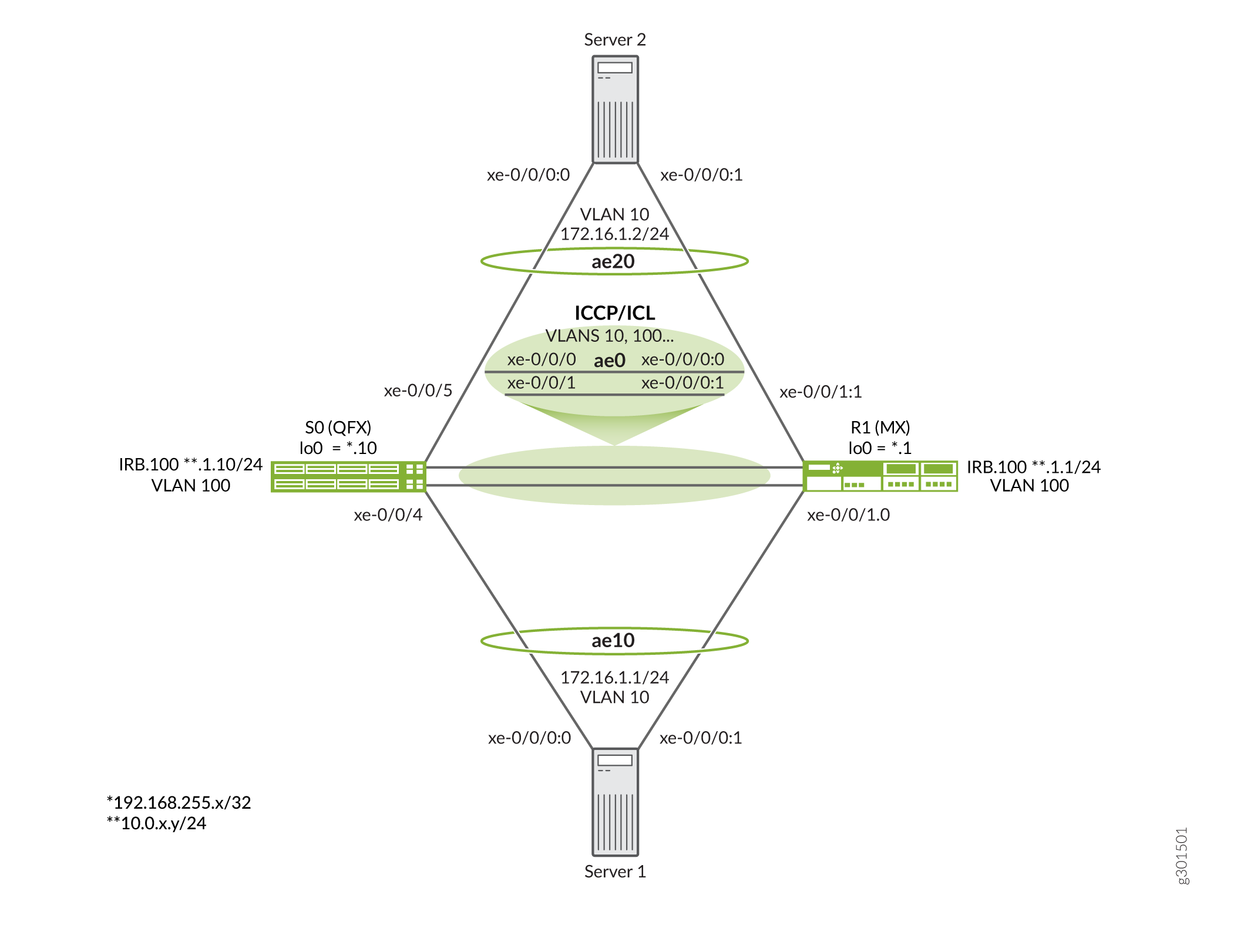
A Figura 3 mostra a topologia usada neste exemplo.
Os principais pontos sobre a topologia incluem:
- O nó S0 é um switch QFX10000, enquanto o nó R1 é um roteador MX960.
- Os roteadores da Série MX são usados para preencher a função dos 2 servidores. Qualquer switch, roteador ou dispositivo de servidor que ofereça suporte a uma interface LAG baseada em LACP convencional pode ser usado neste exemplo.
- Os servidores recebem VLAN 10 e têm uma sub-rede compartilhada. Você espera conectividade de Camada 2 entre os servidores.
- A sessão de ICCP entre os PEs está ancorada em uma interface IRB. Isso é semelhante ao peering BGP entre interfaces de loopback para sobreviver a falhas de link. No entanto, aqui as IRBs são colocadas em uma VLAN compartilhada (VLAN 100) que fornece conectividade de Camada 2 entre os PEs. Isso significa que não é necessário um IGP ou uma rota estática para conectividade entre os IRBs. Como resultado, os IRBs compartilham uma sub-rede IP.
- Este exemplo implanta uma única interface LAG entre os PEs (ae0) para oferecer suporte à funcionalidade ICCP e ICL. Se desejado, você pode executar o ICCP em um pacote AE separado. O uso de vários membros no pacote AE usado para os links ICCP/ICL é altamente recomendado para garantir que eles permaneçam operacionais no caso de falhas de interface ou link individuais.
- Embora em grande parte semelhante, a configuração MC-LAG difere ligeiramente entre os dispositivos PE, dado que eles são plataformas diferentes. Demonstrar essas diferenças de configuração e a interoperabilidade do MC-LAG entre as plataformas é a razão para este exemplo. Certifique-se de acompanhar com qual PE você está interagindo enquanto prossegue pelo exemplo.
Configure os dispositivos
- Configuração rápida da CLI
- Configure o switch S0
- Resultados da S0
- Configure o roteador R1
- Resultados do R1
Configuração rápida da CLI
Para configurar este exemplo rapidamente, copie os seguintes comandos, cole-os em um arquivo de texto, remova quaisquer quebras de linha, altere todos os detalhes necessários para combinar com a configuração da sua rede, copiar e colar os comandos na CLI no nível de [edit] hierarquia. Quando feito, entre no commit modo de configuração para ativar as mudanças.
Switch S0
Neste exemplo, o dispositivo S0 é um switch QFX10000.
set system host-name mc-lag_r0
set chassis aggregated-devices ethernet device-count 10
set interfaces xe-0/0/0 gigether-options 802.3ad ae0
set interfaces xe-0/0/1 gigether-options 802.3ad ae0
set interfaces xe-0/0/4 gigether-options 802.3ad ae10
set interfaces xe-0/0/5 gigether-options 802.3ad ae20
set interfaces ae0 aggregated-ether-options lacp active
set interfaces ae0 unit 0 family ethernet-switching interface-mode trunk
set interfaces ae0 unit 0 family ethernet-switching vlan members all
set interfaces ae10 aggregated-ether-options lacp active
set interfaces ae10 aggregated-ether-options lacp system-id 01:01:01:01:01:01
set interfaces ae10 aggregated-ether-options lacp admin-key 10
set interfaces ae10 aggregated-ether-options mc-ae mc-ae-id 10
set interfaces ae10 aggregated-ether-options mc-ae redundancy-group 1
set interfaces ae10 aggregated-ether-options mc-ae chassis-id 0
set interfaces ae10 aggregated-ether-options mc-ae mode active-active
set interfaces ae10 aggregated-ether-options mc-ae status-control active
set interfaces ae10 unit 0 family ethernet-switching vlan members vlan10
set interfaces ae20 aggregated-ether-options lacp active
set interfaces ae20 aggregated-ether-options lacp system-id 02:02:02:02:02:02
set interfaces ae20 aggregated-ether-options lacp admin-key 20
set interfaces ae20 aggregated-ether-options mc-ae mc-ae-id 20
set interfaces ae20 aggregated-ether-options mc-ae redundancy-group 1
set interfaces ae20 aggregated-ether-options mc-ae chassis-id 1
set interfaces ae20 aggregated-ether-options mc-ae mode active-active
set interfaces ae20 aggregated-ether-options mc-ae status-control standby
set interfaces ae20 unit 0 family ethernet-switching vlan members vlan10
set interfaces irb unit 100 family inet address 10.0.1.10/24
set interfaces lo0 unit 0 family inet address 192.168.255.10/32
set multi-chassis multi-chassis-protection 10.0.1.1 interface ae0
set protocols iccp local-ip-addr 10.0.1.10
set protocols iccp peer 10.0.1.1 session-establishment-hold-time 50
set protocols iccp peer 10.0.1.1 redundancy-group-id-list 1
set protocols iccp peer 10.0.1.1 liveness-detection minimum-interval 1000
set switch-options service-id 100
set vlans vlan10 vlan-id 10
set vlans vlan100 vlan-id 100
set vlans vlan100 l3-interface irb.100
Roteador R1
Neste exemplo, o dispositivo R1 é um roteador da Série MX.
set system host-name mc-lag_r1
set chassis aggregated-devices ethernet device-count 10
set interfaces xe-0/0/0:0 gigether-options 802.3ad ae0
set interfaces xe-0/0/0:1 gigether-options 802.3ad ae0
set interfaces xe-0/0/1:0 gigether-options 802.3ad ae10
set interfaces xe-0/0/1:1 gigether-options 802.3ad ae20
set interfaces ae0 aggregated-ether-options lacp active
set interfaces ae0 unit 0 family bridge interface-mode trunk
set interfaces ae0 unit 0 family bridge vlan-id-list 1-1000
set interfaces ae10 aggregated-ether-options lacp active
set interfaces ae10 aggregated-ether-options lacp system-id 01:01:01:01:01:01
set interfaces ae10 aggregated-ether-options lacp admin-key 10
set interfaces ae10 aggregated-ether-options mc-ae mc-ae-id 10
set interfaces ae10 aggregated-ether-options mc-ae redundancy-group 1
set interfaces ae10 aggregated-ether-options mc-ae chassis-id 1
set interfaces ae10 aggregated-ether-options mc-ae mode active-active
set interfaces ae10 aggregated-ether-options mc-ae status-control standby
set interfaces ae10 unit 0 multi-chassis-protection 10.0.1.10 interface ae0.0
set interfaces ae10 unit 0 family bridge interface-mode access
set interfaces ae10 unit 0 family bridge vlan-id 10
set interfaces ae20 aggregated-ether-options lacp active
set interfaces ae20 aggregated-ether-options lacp system-id 02:02:02:02:02:02
set interfaces ae20 aggregated-ether-options lacp admin-key 20
set interfaces ae20 aggregated-ether-options mc-ae mc-ae-id 20
set interfaces ae20 aggregated-ether-options mc-ae redundancy-group 1
set interfaces ae20 aggregated-ether-options mc-ae chassis-id 0
set interfaces ae20 aggregated-ether-options mc-ae mode active-active
set interfaces ae20 aggregated-ether-options mc-ae status-control active
set interfaces ae20 unit 0 multi-chassis-protection 10.0.1.10 interface ae0.0
set interfaces ae20 unit 0 family bridge interface-mode access
set interfaces ae20 unit 0 family bridge vlan-id 10
set interfaces irb unit 100 family inet address 10.0.1.1/24
set interfaces lo0 unit 0 family inet address 192.168.255.1/32
set protocols iccp local-ip-addr 10.0.1.1
set protocols iccp peer 10.0.1.10 session-establishment-hold-time 50
set protocols iccp peer 10.0.1.10 redundancy-group-id-list 1
set protocols iccp peer 10.0.1.10 liveness-detection minimum-interval 1000
set bridge-domains vlan10 vlan-id 10
set bridge-domains vlan100 vlan-id 100
set bridge-domains vlan100 routing-interface irb.100
set switch-options service-id 10
Servidor 1
Os servidores neste exemplo são roteadores MX. Embora este exemplo se concentre na configuração do MC-LAG nos dispositivos PE, a configuração do servidor é fornecida para integridade. Neste exemplo, o servidor 2 tem a mesma configuração, com exceção de que é atribuído endereço IPv4 172.16.1.2/24 e endereço IPv6 2001:db8:172:16:1:2 .
set system host-name server1
set chassis aggregated-devices ethernet device-count 10
set interfaces xe-0/0/0:0 gigether-options 802.3ad ae10
set interfaces xe-0/0/0:1 gigether-options 802.3ad ae10
set interfaces ae10 aggregated-ether-options lacp active
set interfaces ae10 unit 0 family inet address 172.16.1.1/24
set interfaces ae10 unit 0 family inet6 address 2001:db8:172:16:1::1/64
Configure o switch S0
Procedimento passo a passo
O exemplo a seguir exige que você navegue por vários níveis na hierarquia de configuração. Para obter informações sobre como navegar na CLI, consulte Usando o Editor de CLI no modo de configuração.
Para configurar o Switch S0:
Especifique o número de dispositivos Ethernet agregados suportados no chassi. Apenas 3 LAGs são necessários, por exemplo, mas ter capacidade de pacote AE não utilizada não causa problemas.
[edit chassis]
user@S0# set aggregated-devices ethernet device-count 10
Configure o loopback (se desejado, não é usado neste exemplo) e interfaces IRB, juntamente com o VLAN da interface IRB. Neste exemplo, a interface IRB é usada para ancorar a sessão de ICCP e é atribuída à VLAN 100.
[edit]
user@S0# set interfaces lo0 unit 0 family inet address 192.168.255.10/32
user@S0# set interfaces irb unit 100 family inet address 10.0.1.10/24
user@S0# set vlans vlan100 vlan-id 100
user@S0# set vlans vlan100 l3-interface irb.100
Configure a interface ae0 para oferecer suporte a ICCP e ICL. Certifique-se de incluir todas as VLANs MC-LAG, bem como o VLAN IRB usado para oferecer suporte ao ICCP. Você pode especificar uma lista de VLANs, mas neste exemplo a
allpalavra-chave é usada para garantir rapidamente que todas as VLANs sejam suportadas na interface ae0. Neste exemplo, apenas duas VLANS são necessárias no ISL. O MC-LAG VLAN (10) e o VLAN 100 que oferecem suporte ao ICCP.Para uma unidade de operação adequada 0 deve ser usada para o link ICL no switch da Série QFX porque, ao contrário de um roteador da Série MX, eles não suportam a especificação de nível de unidade do link ICL.
Nota:O switch da Série QFX oferece suporte apenas à especificação de nível de interface do link ICL e assume o uso da unidade 0. Por isso, é importante listar todas as VLANs MC-LAG sob a unidade 0, conforme mostrado. O roteador da Série MX pode suportar especificações globais ou de nível unitário da ICL. Este último método é mostrado mais tarde neste exemplo.
[edit interfaces]
user@S0# set xe-0/0/0 gigether-options 802.3ad ae0
user@S0# set xe-0/0/1 gigether-options 802.3ad ae0
user@S0# set ae0 aggregated-ether-options lacp active
user@S0# set ae0 unit 0 family ethernet-switching interface-mode trunk
user@S0# set ae0 unit 0 family ethernet-switching vlan members all
Especifique as interfaces de membro usadas para o servidor voltado para pacotes Ethernet agregados.
[edit interfaces]
user@S0# set xe-0/0/4 gigether-options 802.3ad ae10
user@S0# set xe-0/0/5 gigether-options 802.3ad ae20
Configure os parâmetros LACP e MC-LAG para o MC-LAG que se conecta ao servidor 1 (ae10). O MC-LAG está definido para o modo ativo-ativo e, neste exemplo, o S0 está definido para ser o nó MC-LAG ativo usando a
status-control activedeclaração. Se o S0 falhar, o R1 assumirá o controle como um nó ativo. Achassis-iddeclaração é usada pelo LACP para o cálculo do número de portas dos links físicos de membros do MC-LAG. Por convenção, o nó ativo recebe uma ID de chassi de 0, enquanto o nó de espera é atribuído 1. Em uma etapa posterior, você configura r1 para ser o nó ativo para o MC-LAG conectado ao servidor 2.O número de identificação de Ethernet agregado de multichasse (mc-ae-id) especifica a qual grupo de agregação de enlaces a interface Ethernet agregada pertence. As interfaces ae10 no S0 e R1 estão configuradas com mc-ae-id 10. Da maneira como a interface ae20 é configurada com mc-ae-id 20 .
A
redundancy-group 1declaração é usada pelo ICCP para associar vários chassis que executam funções de redundância semelhantes e para estabelecer um canal de comunicação para que aplicativos no chassi de peering possam enviar mensagens entre si. As interfaces ae10 e ae20 no S0 e R1 estão configuradas com o mesmo grupo de redundância, o grupo de redundância 1.A
modedeclaração indica se um MC-LAG está no modo de espera ativo ou no modo ativo-ativo. Chassis que estejam no mesmo grupo devem estar no mesmo modo.[edit interfaces ae10] user@S0# set aggregated-ether-options lacp active user@S0# set aggregated-ether-options lacp system-id 01:01:01:01:01:01 user@S0# set aggregated-ether-options lacp admin-key 10 user@S0# set aggregated-ether-options mc-ae mc-ae-id 10 user@S0# set aggregated-ether-options mc-ae redundancy-group 1 user@S0# set aggregated-ether-options mc-ae chassis-id 0 user@S0# set aggregated-ether-options mc-ae mode active-active user@S0# set aggregated-ether-options mc-ae status-control active user@S0# set unit 0 family ethernet-switching vlan members vlan10
Configure os parâmetros LACP e MC-LAG para o MC-LAG que se conecta ao servidor 2 (ae20). O MC-LAG está definido para o modo ativo-ativo e, neste exemplo, o S0 está definido para ser o nó MC-LAG de espera. No caso de falha do R1, o S0 assume o controle como um nó ativo.
[edit interfaces ae20]
user@S0# set aggregated-ether-options lacp active
user@S0# set interfaces ae20 aggregated-ether-options lacp system-id 02:02:02:02:02:02
user@S0# set aggregated-ether-options lacp admin-key 20
user@S0# set aggregated-ether-options mc-ae mc-ae-id 20
user@S0# set aggregated-ether-options mc-ae redundancy-group 1
user@S0# set aggregated-ether-options mc-ae chassis-id 1
user@S0# set aggregated-ether-options mc-ae mode active-active
user@S0# set aggregated-ether-options mc-ae status-control standby
user@S0# set unit 0 family ethernet-switching vlan members v10
Configure a VLAN para os pacotes AE 10 e AE 20.
[edit]
user@S0# set vlans vlan10 vlan-id 10
Configure a ID do serviço de opções de switch.
As portas dentro de um domínio de ponte compartilham as mesmas características de inundação ou transmissão para realizar a ponte de Camada 2.
A declaração global
service-idé necessária para vincular domínios de ponte relacionados entre pares (neste caso, S0 e R1), e deve ser configurada com o mesmo valor.[edit switch-options] user@S0# set service-id 100
Configure os parâmetros do ICCP. Os parâmetros e
peeroslocalparâmetros são definidos para refletir os valores configurados anteriormente para as interfaces IRB locais e remotas, respectivamente. A configuração do peering do ICCP para uma interface IRB (ou loopback) garante que a sessão do ICCP possa permanecer ativa diante de falhas individuais no link.[edit protocols iccp] user@S0# set local-ip-addr 10.0.1.10 user@S0# set peer 10.0.1.1 session-establishment-hold-time 50 user@S0# set peer 10.0.1.1 redundancy-group-id-list 1 user@S0# set peer 10.0.1.10 liveness-detection minimum-interval 1000
Configure a ID do serviço no nível global. Você deve configurar a mesma ID de serviço exclusiva em toda a rede no conjunto de roteadores PE que fornecem o serviço. Essa ID de serviço é necessária quando as interfaces Ethernet agregadas com multichassis fazem parte de um domínio de ponte.
[edit switch-options]
user@S0# set service-id 100
Configure a interface ae0 para funcionar como ICL para os pacotes MC-LAG suportados pelo S0.
[edit multi-chassis]
user@S0# set multi-chassis-protection 10.0.1.1 interface ae0
Nota:No switch da Série QFX, você deve especificar um dispositivo de interface física como o link de proteção de ICL. O mapeamento lógico do nível da unidade de uma ICL para um pacote MC-LAG não é suportado. Para uma operação adequada, você deve garantir que a unidade 0 seja usada para dar suporte à ponte das VLANs MC-LAG na ICL.
Resultados da S0
A partir do modo de configuração, confirme sua configuração entrando no show comando. Se a saída não exibir a configuração pretendida, repita as instruções neste exemplo para corrigir a configuração.
[edit]
user@S0# show
. . .chassis {
    aggregated-devices {
        ethernet {
            device-count 10;
        }
    }
}
interfaces {
    xe-0/0/0 {
        gigether-options {
            802.3ad ae0;
        }
    }
    xe-0/0/1 {
        gigether-options {
            802.3ad ae0;
        }
    }
    xe-0/0/4 {
        gigether-options {
            802.3ad ae10;
        }
    }
    xe-0/0/5 {
        gigether-options {
            802.3ad ae20;
        }
    }
    ae0 {
        aggregated-ether-options {
            lacp {
                active;
            }
        }
        unit 0 {
            family ethernet-switching {
                interface-mode trunk;
                vlan {
                    members all;
                }
            }
        }
    }
    ae10 {
        aggregated-ether-options {
            lacp {
                active;
                system-id 01:01:01:01:01:01;
                admin-key 10;
            }
            mc-ae {
                mc-ae-id 10;
                redundancy-group 1;
                chassis-id 0;
                mode active-active;
                status-control active;
            }
        }
        unit 0 {
            family ethernet-switching {
                vlan {
                    members vlan10;
                }
            }
        }
    }
    ae20 {
        aggregated-ether-options {
            lacp {
                active;
                system-id 02:02:02:02:02:02;
                admin-key 20;
            }
            mc-ae {
                mc-ae-id 20;
                redundancy-group 1;
                chassis-id 1;
                mode active-active;
                status-control standby;
            }
        }
        unit 0 {
            family ethernet-switching {
                vlan {
                    members vlan10;
                }
            }
        }
    }
    irb {
        unit 100 {
            family inet {
                address 10.0.1.10/24;
            }
        }
    }
    lo0 {
        unit 0 {
            family inet {
                address 192.168.255.10/32;
            }
        }
    }
}
multi-chassis {
    multi-chassis-protection 10.0.1.1 {
        interface ae0;
    }
}
protocols {
    iccp {
        local-ip-addr 10.0.1.10;
        peer 10.0.1.1 {
            session-establishment-hold-time 50;
            redundancy-group-id-list 1;
            liveness-detection {
                minimum-interval 1000;
            }
        }
    }
}
switch-options {
    service-id 100;
}
vlans {
    vlan10 {
        vlan-id 10;
    }
    vlan100 {
        vlan-id 100;
        l3-interface irb.100;
    }
}
Configure o roteador R1
Procedimento passo a passo
O exemplo a seguir exige que você navegue por vários níveis na hierarquia de configuração. Para obter informações sobre como navegar na CLI, consulte Usando o Editor de CLI no modo de configuração.
Para configurar o roteador R1:
Especifique o número de interfaces Ethernet agregadas a serem criadas no chassi. Apenas 3 LAGs são necessários, mas ter capacidade de LAG adicional não causa nenhum problema.
[edit chassis]
user@R1# set aggregated-devices ethernet device-count 10
Configure o loopback (se desejado, não é necessário neste exemplo) e interfaces IRB, juntamente com o VLAN da interface IRB. Neste exemplo, a interface IRB é usada para ancorar a sessão do ICCP.
[edit]
user@R1# set interfaces lo0 unit 0 family inet address 192.168.255.1/32
user@R1# set interfaces irb unit 100 family inet address 10.0.1.1/24
user@R1# set bridge-domains vlan100 vlan-id 100
user@R1# set bridge-domains vlan100 routing-interface irb.100
Configure a interface ae0 para oferecer suporte às funcionalidades ICL e ICCP. A
vlan-id-listé usada para oferecer suporte a uma variedade de VLANs que incluem VLAN 100 para ICCP e VLAN 10 para os MC-LAGs. Ao contrário do switch da Série QFX, oallusado como atalho para oferecer suporte a todas as VLANs não é suportado em roteadores da Série MX.Nota:O link ICL deve oferecer suporte a todas as VLANs MC-LAG, bem como à VLAN usada para o ICCP. Neste exemplo, isso significa que, no mínimo, você deve listar VLAN 10 e VLAN 100, dado que o link ae0 oferece suporte tanto ao ISL quanto ao ICCP neste exemplo.
[edit interfaces]
user@R1# set xe-0/0/0:0 gigether-options 802.3ad ae0
user@R1# set xe-0/0/0:1 gigether-options 802.3ad ae0
user@R1# set ae0 aggregated-ether-options lacp active
user@R1# set ae0 unit 0 family bridge interface-mode trunk
user@R1# set ae0 unit 0 family bridge vlan-id-list 2-1000
Especifique os membros a serem incluídos no servidor voltado para pacotes Ethernet agregados no R0.
[edit interfaces]
user@R1# set xe-0/0/1:0 gigether-options 802.3ad ae10
user@R1# set xe-0/0/1:1 gigether-options 802.3ad ae20
Configure os parâmetros LACP e MC-LAG para o MC-LAG que se conecta ao servidor 1 (ae10). O MC-LAG está definido para o modo ativo-ativo e, neste exemplo, o R1 está definido para ser o nó MC-LAG de espera usando a
status-control standbydeclaração. Isso faz do S0 o nó MC-LAG ativo para ae10 quando está operacional. Se o S0 falhar, o R1 assume o controle como um nó ativo. Achassis-iddeclaração é usada pelo LACP para o cálculo do número de portas dos links físicos de membros do MC-LAG. Por convenção, o nó ativo é atribuído à ID do chassi de 0, enquanto o nó de espera é atribuído 1.O número
mc-ae-idde identificação de Ethernet agregado de multichasse especifica qual grupo de agregação de enlaces a interface Ethernet agregada pertence. As interfaces ae10 no S0 e R1 estão configuradas com mc-ae-id 10. Da maneira como a interface ae20 é configurada com mc-ae-id 20.A
redundancy-group 1declaração é usada pelo ICCP para associar vários chassis que executam funções de redundância semelhantes e para estabelecer um canal de comunicação para que aplicativos no chassi de peering possam enviar mensagens entre si. As interfaces ae10 e ae20 no S0 e R1 estão configuradas com o mesmo grupo de redundância, o grupo de redundância 1.A
modedeclaração indica se um MC-LAG está no modo de espera ativo ou no modo ativo-ativo. Chassis que estejam no mesmo grupo devem estar no mesmo modo.Este exemplo demonstra o suporte ao roteador da Série MX para a especificação da interface ICL no nível da unidade (sob a unidade MC-LAG, conforme mostrado abaixo). Se desejado, o link de proteção ICL pode ser especificado globalmente no nível do dispositivo físico (com a
[edit multi-chassis multi-chassis-protection]unidade 0 assumida) na hierarquia, como foi mostrado para o switch S0 da Série QFX.[edit interfaces ae10] user@R1# set aggregated-ether-options lacp active user@R1# set aggregated-ether-options lacp system-id 01:01:01:01:01:01 user@R1# set aggregated-ether-options lacp admin-key 10 user@R1# set aggregated-ether-options mc-ae mc-ae-id 10 user@R1# set aggregated-ether-options mc-ae redundancy-group 1 user@R1# set aggregated-ether-options mc-ae chassis-id 1 user@R1# set aggregated-ether-options mc-ae mode active-active user@R1# set aggregated-ether-options mc-ae status-control standby user@R1# set ae10 unit 0 family bridge interface-mode access user@R1# set ae10 unit 0 family bridge vlan-id 10 user@R1# set ae10 unit 0 multi-chassis-protection 10.0.1.10 interface ae0.0
Nota:Na plataforma MX, você pode especificar a interface de ICL usando uma declaração de dispositivo físico de nível global na
edit multi-chassis multi-chassis-protectionhierarquia ou, como mostrado aqui, no nível de unidade lógica dentro do pacote MC-LAG. Os switches da Série QFX oferecem suporte apenas à especificação de nível global do dispositivo físico.Configure os parâmetros LACP e MC-LAG para o MC-LAG que se conecta ao servidor 2 (ae20). O MC-LAG está definido para o modo ativo-ativo e, neste exemplo, o R1 está definido para ser o nó MC-LAG ativo. No caso de falha do R1, o S0 assume o controle como um nó ativo para o Ae20 MC-LAG.
[edit interfaces ae20]
user@R1# set aggregated-ether-options lacp active
user@R1# set aggregated-ether-options lacp system-id 02:02:02:02:02:02
user@R1# set aggregated-ether-options lacp admin-key 20
user@R1# set aggregated-ether-options mc-ae mc-ae-id 20
user@R1# set aggregated-ether-options mc-ae redundancy-group 1
user@R1# set aggregated-ether-options mc-ae chassis-id 0
user@R1# set aggregated-ether-options mc-ae mode active-active
user@R1# set aggregated-ether-options mc-ae status-control active
user@R1# set unit 0 family bridge interface-mode access
user@R1# set unit 0 family bridge vlan-id 10
user@R1# set unit 0 multi-chassis-protection 10.0.1.10 interface ae0.0
Configure a VLAN para os pacotes ae10 e ae20.
Nota:No roteador da Série MX você define VLANs sob a
[edit bridge-domains]hierarquia. No switch da Série WFX isso é feito na[edit vlans]hierarquia. Essa é uma das diferenças entre o switch da Série QFX e o roteador da Série MX.[edit bridge-domains] user@R1# set vlan10 vlan-id 10
Configure a ID do serviço de opções de switch.
As portas dentro de um domínio de ponte compartilham as mesmas características de inundação ou transmissão para realizar a ponte de Camada 2.
A declaração global
service-idé necessária para vincular domínios de ponte relacionados entre pares (neste caso, S0 e R1), e deve ser configurada com o mesmo valor.[edit switch-options] user@R1# set service-id 100
Configure os parâmetros do ICCP. Os parâmetros e os
localparâmetrospeersão definidos para refletir os valores configurados anteriormente nas interfaces IRB local e remota, respectivamente. A configuração do peering do ICCP para uma interface IRB (ou loopback) garante que a sessão do ICCP possa permanecer ativa diante de falhas individuais no link.[edit protocols iccp] user@R1# set local-ip-addr 10.0.1.1 user@R1# set peer 10.0.1.10 session-establishment-hold-time 50 user@R1# set peer 10.0.1.10 redundancy-group-id-list 1 user@R1# set peer 10.0.1.10 liveness-detection minimum-interval 1000
Configure a ID do serviço no nível global. Você deve configurar a mesma configuração exclusiva em toda a rede para um serviço no conjunto de dispositivos PE que fornecem o serviço. Esse ID de serviço é necessário se as interfaces Ethernet agregadas de multichassis fizerem parte de um domínio de ponte.
[edit switch-options]
user@R1# set service-id 100
Resultados do R1
A partir do modo de configuração, confirme sua configuração entrando no show comando. Se a saída não exibir a configuração pretendida, repita as instruções neste exemplo para corrigir a configuração.
[edit]
user@R1# show
. . .
chassis {
    aggregated-devices {
        ethernet {
            device-count 10;
        }
    }
}
interfaces {
    xe-0/0/0:0 {
        gigether-options {
            802.3ad ae0;
        }
    }
    xe-0/0/0:1 {
        gigether-options {
            802.3ad ae0;
        }
    }
    xe-0/0/0:2 {
        gigether-options {
            802.3ad ae1;
        }
    }
    xe-0/0/0:3 {
        gigether-options {
            802.3ad ae1;
        }
    }
    xe-0/0/1:0 {
        gigether-options {
            802.3ad ae10;
        }
    }
    xe-0/0/1:1 {
        gigether-options {
            802.3ad ae20;
        }
    }
    ae0 {
        aggregated-ether-options {
            lacp {
                active;
            }
        }
        unit 0 {
            family bridge {
                interface-mode trunk;
                vlan-id-list 2-1000;
            }
        }
    }
    ae10 {
        aggregated-ether-options {
            lacp {
                active;
                system-id 01:01:01:01:01:01;
                admin-key 10;
            }
            mc-ae {
                mc-ae-id 10;
                redundancy-group 1;
                chassis-id 1;
                mode active-active;
                status-control standby;
            }
        }
        unit 0 {
            multi-chassis-protection 10.0.1.10 {
                interface ae0.0;
            }
            family bridge {
                interface-mode access;
                vlan-id 10;
            }
        }
    }
    ae20 {
        aggregated-ether-options {
            lacp {
                active;
                system-id 02:02:02:02:02:02;
                admin-key 20;
            }
            mc-ae {
                mc-ae-id 20;
                redundancy-group 1;
                chassis-id 0;
                mode active-active;
                status-control active;
            }
        }
        unit 0 {
            multi-chassis-protection 10.0.1.10 {
                interface ae0.0;
            }
            family bridge {
                interface-mode access;
                vlan-id 10;
            }
        }
    }
    irb {
        unit 100 {
            family inet {
                address 10.0.1.1/24;
            }
        }
    }
    lo0 {
        unit 0 {
            family inet {
                address 192.168.255.1/32;
            }
        }
    }
}
protocols {
    iccp {
        local-ip-addr 10.0.1.1;
        peer 10.0.1.10 {
            session-establishment-hold-time 50;
            redundancy-group-id-list 1;
            liveness-detection {
                minimum-interval 1000;
            }
        }
    }
}
bridge-domains {
    vlan10 {
        vlan-id 10;
    }
    vlan100 {
        vlan-id 100;
        routing-interface irb.100;
    }
}
switch-options {
    service-id 100;
}
Verificação
Confirme que a configuração está funcionando corretamente executando os seguintes comandos de modo operacional:
show iccpshow interfaces mc-aeshow interfaces aeX (0, 10, and 20)No switch da Série QFX, use o
show vlanse osshow ethernet-switching tablecomandosNo roteador da Série MX, use o
show bridge mac-tablecomandoVerifique a conectividade de Camada 2 entre os servidores
Selecione comandos de verificação para mostrar a saída esperada. Começamos com o show iccp comando da S0. Se a sessão do ICCP não for estabelecida, emita o comando de ping entre as interfaces IRB para garantir a conectividade de Camada 2 esperada no link Ae0 ICCP/ICL:
user@S0# show iccp
Redundancy Group Information for peer 10.0.1.1
  TCP Connection       : Established
  Liveliness Detection : Up
  Redundancy Group ID          Status
    1                           Up

Client Application: l2ald_iccpd_client
  Redundancy Group IDs Joined: 1

Client Application: lacpd
  Redundancy Group IDs Joined: 1
Em seguida, executamos o show interfaces mc-ae extensive comando na S0. A saída confirma o estado ativo-ativo esperado e o estado ativo de controle de status ativo/espera para ambos os MC-LAGs. Lembre-se que o S0 é o nó ativo de controle de status para ae10 e o nó de espera para ae20 neste exemplo:
user@S0# show interfaces mc-lag extensive
 Member Link                  : ae10
 Current State Machine's State: mcae active state
 Local Status                 : active
 Local State                  : up
 Peer Status                  : active
 Peer State                   : up
     Logical Interface        : ae10.0
     Topology Type            : bridge
     Local State              : up
     Peer State               : up
     Peer Ip/MCP/State        : 10.0.1.1 ae0.0 up

 MCAE Configuration
     Redundancy Group         : 1
     MCAE ID                  : 10
     MCAE Mode                : active_active
     Status Control           : active
     Chassis ID               : 0
 LACP Configuration
     System ID                : 01:01:01:01:01:01
     Admin Key                : 10
 LACP Information
     Local Partner System ID  : 2c:6b:f5:20:55:c0
     Peer Partner System ID   : 2c:6b:f5:20:55:c0

 Member Link                  : ae20
 Current State Machine's State: mcae active state
 Local Status                 : active
 Local State                  : up
 Peer Status                  : active
 Peer State                   : up
     Logical Interface        : ae20.0
     Topology Type            : bridge
     Local State              : up
     Peer State               : up
     Peer Ip/MCP/State        : 10.0.1.1 ae0.0 up

 MCAE Configuration
     Redundancy Group         : 1
     MCAE ID                  : 20
     MCAE Mode                : active_active
     Status Control           : standby
     Chassis ID               : 1
 LACP Configuration
     System ID                : 02:02:02:02:02:02
     Admin Key                : 20
 LACP Information
     Local Partner System ID  : 2c:6b:f5:13:24:c0
     Peer Partner System ID   : 2c:6b:f5:13:24:c0
O show interfaces comando é usado para confirmar que os pacotes ICCP/ICL e MC-LAG estão funcionando. Para a brevidade, apenas a saída para o pacote ae10 é mostrada. Todas as interfaces AE (ae0, ae10 e ae20) devem estar ativas:
user@S0# show interfaces ae10
 Physical interface: ae10 (MC-AE-10, active), Enabled, Physical link is Up
  Interface index: 670, SNMP ifIndex: 561
  Link-level type: Ethernet, MTU: 1514, Speed: 10Gbps, BPDU Error: None, Ethernet-Switching Error: None, MAC-REWRITE Error: None,
  Loopback: Disabled, Source filtering: Disabled, Flow control: Disabled, Minimum links needed: 1, Minimum bandwidth needed: 1bps
  Device flags   : Present Running
  Interface flags: SNMP-Traps Internal: 0x4000
  Current address: 02:05:86:72:a9:f7, Hardware address: 02:05:86:72:a9:f7
  Last flapped   : 2021-04-08 11:56:43 PDT (02:37:24 ago)
  Input rate     : 0 bps (0 pps)
  Output rate    : 992 bps (0 pps)

  Logical interface ae10.0 (Index 578) (SNMP ifIndex 562)
    Flags: Up SNMP-Traps 0x24024000 Encapsulation: Ethernet-Bridge
    Statistics        Packets        pps         Bytes          bps
    Bundle:
        Input :          9454          0        963310          776
        Output:          9429          0       1204640          968
    Adaptive Statistics:
        Adaptive Adjusts:          0
        Adaptive Scans  :          0
        Adaptive Updates:          0
    Protocol eth-switch, MTU: 1514
Os show vlans detail comandos e os comandos show ethernet-switching table são usados para confirmar a definição e o mapeamento de VLAN para as interfaces ICCP/ICL e MC-LAG no dispositivo S0:
user@S0# show vlans detail
 Routing instance: default-switch
VLAN Name: vlan10                            State: Active
Tag: 10
Internal index: 3, Generation Index: 3, Origin: Static
MAC aging time: 300 seconds
VXLAN Enabled : No
Interfaces:
    ae0.0*,tagged,trunk
    ae10.0*,untagged,access
    ae20.0*,untagged,access
Number of interfaces: Tagged 1    , Untagged 2
Total MAC count: 2

Routing instance: default-switch
VLAN Name: vlan100                        State: Active
Tag: 100
Internal index: 2, Generation Index: 2, Origin: Static
MAC aging time: 300 seconds
Layer 3 interface: irb.100
VXLAN Enabled : No
Interfaces:
    ae0.0*,tagged,trunk
Number of interfaces: Tagged 1    , Untagged 0
Total MAC count:

show ethernet-switching table
MAC flags (S - static MAC, D - dynamic MAC, L - locally learned, P - Persistent static, C - Control MAC
           SE - statistics enabled, NM - non configured MAC, R - remote PE MAC, O - ovsdb MAC)


Ethernet switching table : 2 entries, 2 learned
Routing instance : default-switch
    Vlan                MAC                 MAC         Age    Logical                NH        RTR
    name                address             flags              interface              Index     ID
    vlan10                 2c:6b:f5:13:24:c2   DLR           -   ae20.0                 0         0
    vlan10                 2c:6b:f5:20:55:c3   DL            -   ae10.0                 0         0
Por fim, você faz um ping entre o servidor 1 e 2 para confirmar a conectividade de Camada 2:
user@Server1# ping 172.16.1.2 count 2
 PING 172.16.1.2 (172.16.1.2): 56 data bytes
64 bytes from 172.16.1.2: icmp_seq=0 ttl=64 time=56.529 ms
64 bytes from 172.16.1.2: icmp_seq=1 ttl=64 time=117.029 ms

--- 172.16.1.2 ping statistics ---
2 packets transmitted, 2 packets received, 0% packet loss
round-trip min/avg/max/stddev = 56.529/86.779/117.029/30.250 ms
user@Server1# ping 2001:db8:172:16:1::2 count 2
PING6(56=40+8+8 bytes) 2001:db8:172:16:1::1 --> 2001:db8:172:16:1::2
16 bytes from 2001:db8:172:16:1::2, icmp_seq=0 hlim=64 time=154.164 ms
16 bytes from 2001:db8:172:16:1::2, icmp_seq=1 hlim=64 time=167.032 ms

--- 2001:db8:172:16:1::2 ping6 statistics ---
2 packets transmitted, 2 packets received, 0% packet loss
round-trip min/avg/max/std-dev = 154.164/160.598/167.032/6.434 ms
Exemplo: Configuração da agregação de enlaces multichassis em switches EX9200 no núcleo para redes de campus
O MC-LAG em uma configuração de campus permite que você conecte dois ou mais links físicos em um enlace lógico entre switches de agregação de núcleo ou de acesso de agregação. O MC-LAG melhora a disponibilidade fornecendo links ativos/ativos entre vários switches em um grupo de agregação de enlaces padrão (LAG), elimina a necessidade do Protocolo spanning tree (STP) e oferece convergência de Camada 2 mais rápida após falhas no link e no dispositivo. Com vários caminhos de rede ativos, o MC-LAG permite que você carregue o tráfego de equilíbrio entre os vários links físicos. Se um link falhar, o tráfego pode ser encaminhado pelos outros links disponíveis e o link agregado permanece disponível.
- Requisitos
- Visão geral
- Configuração
- (Opcional) Configuração do RSTP
- (Opcional) Configuração do IGMP Snooping
- (Opcional) Configuração do VRRP
- (Opcional) Configuração da sincronização de endereços MAC
- (Opcional) Configuração do OSPF
- (Opcional) Configuração do PIM
- (Opcional) Configuração do retransmissão DHCP
- Verificação
Requisitos
Este exemplo usa os seguintes componentes de hardware e software:
Versão Junos OS 13.2R5.10 para a Série EX
Dois switches EX9200
Este exemplo de configuração foi testado usando a versão de software listada e assume-se que funcione em todas as versões posteriores.
Antes de configurar um MC-LAG, certifique-se de entender como:
Configure interfaces Ethernet agregadas em um switch. Veja a configuração de uma interface de ethernet agregada.
Configure o Link Aggregation Control Protocol (LACP) em interfaces Ethernet agregadas em um switch. Veja configuração do Ethernet LACP agregado (procedimento CLI).
Visão geral
Neste exemplo, você configura um MC-LAG em dois switches, consistindo em duas interfaces Ethernet agregadas, um link de proteção de link de interchasse (ICL-PL), link de proteção multichassis para o ICL-PL, ICCP para os pares que hospedam o MC-LAG e conectividade de Camada 3 entre os pares MC-LAG. A conectividade de camada 3 é necessária para o ICCP.
Topologia
A topologia usada neste exemplo consiste em dois switches hospedando um MC-LAG. Os dois switches estão conectados a um switch EX4600 e a um roteador MX80. A Figura 4 mostra a topologia deste exemplo.
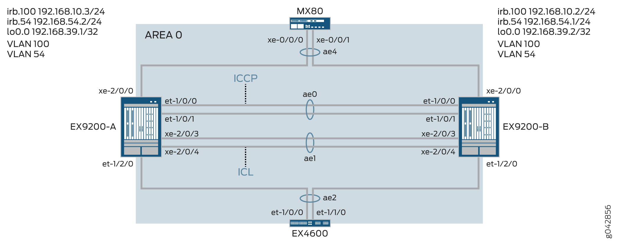 de topologia
A Tabela 1 detalha a topologia usada neste exemplo de configuração.
| Grupo de agregação de links multichassis | dehardware base | dohostname |
|---|---|---|
EX9200-A EX9200-B |
EX9200 EX9200 |
ae0 é configurada como uma interface Ethernet agregada, e é usada como um link ICCP. As interfaces a seguir fazem parte do ae0: et-1/0/0 e et-1/0/1 no EX9200-A e et-1/0/0 e et-1/0/1 no EX9200-B. ae1 é configurada como uma interface Ethernet agregada e é usada como um link ICL, e as duas interfaces a seguir fazem parte da ae1: xe-2/0/3 e xe-2/0/4 no EX9200-A e xe-2/0/3 e xe-2/0/4 no EX9200-B. ae2 está configurado como um MC-LAG, e as seguintes interfaces fazem parte do ae2: et-1/2/0 no EX9200-A e et-1/2/0 no EX9200-B. ae4 está configurada como um MC-LAG, e as seguintes interfaces fazem parte do ae4: xe-2/0/0 no EX9200-A e xe-2/0/0 no EX9200-B. |
Configuração
- Configuração rápida da CLI
- Configuração do MC-LAG no Switch A
- Configuração do MC-LAG no Switch B
- Resultados
Configuração rápida da CLI
Para configurar rapidamente este exemplo, copie os seguintes comandos, cole-os em um arquivo de texto, remova quaisquer quebras de linha, altere todos os detalhes necessários para combinar com a configuração da sua rede, copiar e colar os comandos na CLI no nível de [edit] hierarquia e, em seguida, entrar no commit modo de configuração.
EX9200-A
set chassis aggregated-devices ethernet device-count 20
set interfaces et-1/0/0 ether-options 802.3ad ae0
set interfaces et-1/0/1 ether-options 802.3ad ae0
set interfaces et-1/2/0 ether-options 802.3ad ae2
set interfaces xe-2/0/3 hold-time up 100
set interfaces xe-2/0/3 hold-time down 9000
set interfaces xe-2/0/3 ether-options 802.3ad ae1
set interfaces xe-2/0/4 hold-time up 100
set interfaces xe-2/0/4 hold-time down 9000
set interfaces xe-2/0/4 ether-options 802.3ad ae1
set interfaces xe-2/0/0 ether-options 802.3ad ae4
set interfaces ae0 aggregated-ether-options lacp active
set interfaces ae0 aggregated-ether-options lacp periodic fast
set interfaces ae0 unit 0 family inet address 192.168.90.1/24
set interfaces ae1 description ICL-LINK
set interfaces ae1 aggregated-ether-options lacp active
set interfaces ae1 aggregated-ether-options lacp periodic fast
set interfaces ae1 unit 0 family ethernet-switching interface-mode trunk
set interfaces ae1 unit 0 family ethernet-switching vlan members all
set interfaces ae2 aggregated-ether-options lacp active
set interfaces ae2 aggregated-ether-options lacp periodic fast
set interfaces ae2 aggregated-ether-options lacp system-id 00:01:02:03:04:05
set interfaces ae2 aggregated-ether-options lacp admin-key 3
set interfaces ae2 aggregated-ether-options mc-ae mc-ae-id 3
set interfaces ae2 aggregated-ether-options mc-ae redundancy-group 1
set interfaces ae2 aggregated-ether-options mc-ae chassis-id 0
set interfaces ae2 aggregated-ether-options mc-ae mode active-active
set interfaces ae2 aggregated-ether-options mc-ae status-control active
set interfaces ae2 aggregated-ether-options mc-ae init-delay-time 520
set interfaces ae2 aggregated-ether-options mc-ae events iccp-peer-down prefer-status-control-active
set interfaces ae2 unit 0 family ethernet-switching interface-mode trunk
set interfaces ae2 unit 0 family ethernet-switching vlan members all
set interfaces ae4 aggregated-ether-options lacp active
set interfaces ae4 aggregated-ether-options lacp periodic fast
set interfaces ae4 aggregated-ether-options lacp system-id 00:01:02:03:04:06
set interfaces ae4 aggregated-ether-options lacp admin-key 7
set interfaces ae4 aggregated-ether-options mc-ae mc-ae-id 7
set interfaces ae4 aggregated-ether-options mc-ae redundancy-group 1
set interfaces ae4 aggregated-ether-options mc-ae chassis-id 0
set interfaces ae4 aggregated-ether-options mc-ae mode active-active
set interfaces ae4 aggregated-ether-options mc-ae status-control active
set interfaces ae4 aggregated-ether-options mc-ae init-delay-time 520
set interfaces ae4 aggregated-ether-options mc-ae events iccp-peer-down prefer-status-control-active
set interfaces ae4 unit 0 family ethernet-switching interface-mode trunk
set interfaces ae4 unit 0 family ethernet-switching vlan members v54
set vlans rack_1 vlan-id 100
set vlans rack_1 vlan-id 54
set vlans rack_1 l3-interface irb.100
set vlans v54 l3-interface irb.54
set interfaces irb unit 54 family inet address 192.168.54.2/24 arp 192.168.54.1 l2-interface ae1.0
set interfaces irb unit 54 family inet address 192.168.54.2/24 arp 192.168.54.1 mac 3c:8a:b0:85:78:70
set interfaces irb unit 100 family inet address 192.168.10.3/24 arp 192.168.10.2 l2-interface ae1.0
set interfaces irb unit 100 family inet address 192.168.10.3/24 arp 192.168.10.2 mac 3c:8a:b0:85:78:70
set interfaces lo0 unit 0 family inet address 192.168.39.1/32
set protocols iccp local-ip-addr 192.168.39.1
set protocols iccp peer 192.168.39.2 session-establishment-hold-time 50
set protocols iccp peer 192.168.39.2 redundancy-group-id-list 1
set protocols iccp peer 192.168.39.2 backup-liveness-detection backup-peer-ip 10.105.5.6
set protocols iccp peer 192.168.39.2 liveness-detection minimum-interval 2000
set protocols iccp peer 192.168.39.2 liveness-detection multiplier 4
set multi-chassis multi-chassis-protection 192.168.39.2 interface ae1
set switch-options service-id 1
EX9200-B
set chassis aggregated-devices ethernet device-count 20
set interfaces et-1/0/0 ether-options 802.3ad ae0
set interfaces et-1/0/1 ether-options 802.3ad ae0
set interfaces et-1/2/0 ether-options 802.3ad ae2
set interfaces xe-2/0/0 ether-options 802.3ad ae4
set interfaces xe-2/0/3 hold-time up 100
set interfaces xe-2/0/3 hold-time down 9000
set interfaces xe-2/0/3 ether-options 802.3ad ae1
set interfaces xe-2/0/4 hold-time up 100
set interfaces xe-2/0/4 hold-time down 9000
set interfaces xe-2/0/4 ether-options 802.3ad ae1
set interfaces ae0 aggregated-ether-options lacp active
set interfaces ae0 aggregated-ether-options lacp periodic fast
set interfaces ae0 unit 0 family inet address 192.168.90.2/24
set interfaces ae1 description ICL-LINK
set interfaces ae1 aggregated-ether-options lacp active
set interfaces ae1 aggregated-ether-options lacp periodic fast
set interfaces ae1 unit 0 family ethernet-switching interface-mode trunk
set interfaces ae1 unit 0 family ethernet-switching vlan members all
set interfaces ae2 aggregated-ether-options lacp active
set interfaces ae2 aggregated-ether-options lacp periodic fast
set interfaces ae2 aggregated-ether-options lacp system-id 00:01:02:03:04:05
set interfaces ae2 aggregated-ether-options lacp admin-key 3
set interfaces ae2 aggregated-ether-options mc-ae mc-ae-id 3
set interfaces ae2 aggregated-ether-options mc-ae redundancy-group 1
set interfaces ae2 aggregated-ether-options mc-ae chassis-id 1
set interfaces ae2 aggregated-ether-options mc-ae mode active-active
set interfaces ae2 aggregated-ether-options mc-ae init-delay-time 520
set interfaces ae2 aggregated-ether-options mc-ae events
set interfaces ae2 aggregated-ether-options mc-ae status-control standby
set interfaces ae2 unit 0 family ethernet-switching interface-mode trunk
set interfaces ae2 unit 0 family ethernet-switching vlan members all
set interfaces ae4 aggregated-ether-options lacp active
set interfaces ae4 aggregated-ether-options lacp periodic fast
set interfaces ae4 aggregated-ether-options lacp system-id 00:01:02:03:04:06
set interfaces ae4 aggregated-ether-options lacp admin-key 7
set interfaces ae4 aggregated-ether-options mc-ae mc-ae-id 7
set interfaces ae4 aggregated-ether-options mc-ae redundancy-group 1
set interfaces ae4 aggregated-ether-options mc-ae chassis-id 1
set interfaces ae4 aggregated-ether-options mc-ae mode active-active
set interfaces ae4 aggregated-ether-options mc-ae status-control standby
set interfaces ae4 aggregated-ether-options mc-ae init-delay-time 520
set interfaces ae4 unit 0 family ethernet-switching interface-mode trunk
set interfaces ae4 unit 0 family ethernet-switching vlan members v54
set vlans rack_1 vlan-id 100
set vlans rack_1 l3-interface irb.100
set vlans v54 vlan-id 54
set vlans v54 l3-interface irb.54
set interfaces irb unit 54 family inet address 192.168.54.1/24 arp 192.168.54.2 l2-interface ae1.0
set interfaces irb unit 54 family inet address 192.168.54.1/24 arp 192.168.54.2 mac 00:1f:12:b6:6f:f0
set interfaces irb unit 100 family inet address 192.168.10.2/24 arp 192.168.10.3 l2-interface ae1.0
set interfaces irb unit 100 family inet address 192.168.10.2/24 arp 192.168.10.3 mac 00:1f:12:b6:6f:f0
set interfaces lo0 unit 0 family inet address 192.168.39.2/32
set protocols iccp local-ip-addr 192.168.39.2
set protocols iccp peer 192.168.39.1 session-establishment-hold-time 50
set protocols iccp peer 192.168.39.1 redundancy-group-id-list 1
set protocols iccp peer 192.168.39.1 backup-liveness-detection backup-peer-ip 10.105.5.5
set protocols iccp peer 192.168.39.1 liveness-detection minimum-interval 2000
set protocols iccp peer 192.168.39.1 liveness-detection multiplier 4
set multi-chassis multi-chassis-protection 192.168.39.1 interface ae1
set switch-options service-id 1
Configuração do MC-LAG no Switch A
Procedimento passo a passo
O exemplo a seguir exige que você navegue por vários níveis na hierarquia de configuração.
Configure o número de interfaces Ethernet agregadas a serem criadas no Switch A.
[edit chassis]
user@switch# set aggregated-devices ethernet device-count 20
Adicione interfaces de membros às interfaces Ethernet agregadas que serão usadas para a interface Inter-Chassis Control Protocol (ICCP).
[edit interfaces]
user@switch# set et-1/0/0 ether-options 802.3ad ae0
user@switch# set et-1/0/1 ether-options 802.3ad ae0
Especifique as interfaces de membro que pertencem à interface ae2.
[edit interfaces]
user@switch# set et-1/2/0 ether-options 802.3ad ae2
Configure as interfaces de membro para o link de interchasse (ICL) com um valor de tempo de espera maior do que o temporizador BFD configurado para evitar que a ICL seja anunciada como sendo baixa antes que o link ICCP seja desativado.
Se a ICL cair antes que o link ICCP seja desativado, a interface MC-LAG configurada como o peer de controle de status de standby sobe e desce. A interface subindo e baixando causa um atraso na convergência.
[edit interfaces]
user@switch# set xe-2/0/3 hold-time up 100
user@switch# set xe-2/0/3 hold-time down 9000
user@switch# set xe-2/0/3 ether-options 802.3ad ae1
user@switch# set xe-2/0/4 hold-time up 100
user@switch# set xe-2/0/4 hold-time down 9000
user@switch# set xe-2/0/4 ether-options 802.3ad ae1
Especifique os membros que pertencem à ae4.
Especifique os membros que pertencem à ae4.
[edit interfaces]
user@switch# set xe-2/0/0 ether-options 802.3ad ae4
Configure o ae0 como uma interface de Camada 3.
[edit interfaces]
user@switch# set ae0 aggregated-ether-options lacp active
user@switch# set ae0 aggregated-ether-options lacp periodic fast
user@switch# set ae0 unit 0 family inet address 192.168.90.1/24
Configure ae1 como uma interface de Camada 2.
[edit interfaces]
user@switch# set ae1 description ICL-LINK
user@switch# set ae1 aggregated-ether-options lacp active
user@switch# set ae1 aggregated-ether-options lacp periodic fast
Configure uma interface de tronco entre EX9200-A e EX9200-B.
[edit interfaces]
user@switch# set ae1 unit 0 family ethernet-switching interface-mode trunk
user@switch# set ae1 unit 0 family ethernet-switching vlan members all
Configure os parâmetros LACP em ae2.
[edit interfaces]
user@switch# set ae2 aggregated-ether-options lacp active
user@switch# set ae2 aggregated-ether-options lacp periodic fast
Configure a ID do sistema LACP.
[edit interfaces]
user@switch# set ae2 aggregated-ether-options lacp system-id 00:01:02:03:04:06
Configure as propriedades da interface MC-AE.
[edit interfaces]
user@switch# set ae2 aggregated-ether-options lacp admin-key 3
user@switch# set ae2 aggregated-ether-options mc-ae mc-ae-id 3
user@switch# set ae2 aggregated-ether-options mc-ae redundancy-group 1
Especifique um ID de chassi exclusivo para o MC-LAG do qual a interface Ethernet agregada pertence.
[edit interfaces]
user@switch# set ae2 aggregated-ether-options mc-ae chassis-id 0
Especifique o modo do MC-LAG a que a interface Ethernet agregada pertence.
[edit interfaces]
user@switch# set ae2 aggregated-ether-options mc-ae mode active-active
Configure o controle de status no switch que hospeda o MC-LAG.
Se um switch estiver em modo ativo, o outro switch deve estar em modo de espera.
[edit interfaces]
user@switch# set ae2 aggregated-ether-options mc-ae status-control active
Especifique o tempo em segundos quando as adjacências de roteamento devem se formar.
[edit interfaces]
user@switch# set ae2 aggregated-ether-options mc-ae init-delay-time 520
Especifique se um peer do grupo MC-LAG cair, o peer configurado como ativo de controle de status se tornará o peer ativo.
[edit interfaces]
user@switch# set ae2 aggregated-ether-options mc-ae events iccp-peer-down prefer-status-control-active
Configure o ae2 como uma porta-tronco com a adesão em todas as VLANs.
[edit interfaces]
user@switch# set ae2 unit 0 family ethernet-switching interface-mode trunk
user@switch# set ae2 unit 0 family ethernet-switching vlan members all
Configure os parâmetros LACP em ae4.
[edit interfaces]
user@switch# set ae4 aggregated-ether-options lacp active
user@switch# set ae4 aggregated-ether-options lacp periodic fast
Especifique a chave da administração LACP.
[edit interfaces]
user@switch# set ae4 aggregated-ether-options lacp system-id 00:01:02:03:04:06
user@switch# set ae4 aggregated-ether-options lacp admin-key 7
user@switch# set ae4 aggregated-ether-options mc-ae mc-ae-id 7
user@switch# set ae4 aggregated-ether-options mc-ae redundancy-group 1
Especifique um ID de chassi exclusivo para o MC-LAG do qual a interface Ethernet agregada pertence.
[edit interfaces]
user@switch# set ae4 aggregated-ether-options mc-ae chassis-id 0
user@switch# set ae4 aggregated-ether-options mc-ae mode active-active
Configure o controle de status no switch que hospeda o MC-LAG.
Se um switch estiver em modo ativo, o outro switch deve estar em modo de espera.
[edit interfaces]
user@switch# set ae4 aggregated-ether-options mc-ae status-control active
user@switch# set ae4 aggregated-ether-options mc-ae init-delay-time 520
user@switch# set ae4 aggregated-ether-options mc-ae events iccp-peer-down prefer-status-control-active
Configure o ae4 como uma interface de Camada 2.
[edit interfaces]
user@switch# set ae4 unit 0 family ethernet-switching interface-mode trunk
user@switch# set ae4 unit 0 family ethernet-switching vlan members v54
Configure o VLAN rack_1 e configure uma interface IRB de Camada 3 no VLAN rack_1.
[edit vlans]
user@switch# set rack_1 vlan-id 100
user@switch# set rack_1 l3-interface irb.100
Configure rack_1 de VLAN.
[edit vlans]
user@switch# set rack_1 vlan-id 54
Configure a VLAN 54 e configure uma IRB de Camada 3 na VLAN 54.
[edit vlans]
user@switch# set v54 vlan-id 54
user@switch# set v54 l3-interface irb.54
Configure uma interface IRB na VLAN 54.
Você deve configurar o ARP estático nos pares MC-LAG para permitir que os protocolos de roteamento passem pela interface IRB.
[edit interfaces]
user@switch# set irb unit 54 family inet address 192.168.54.2/24 arp 192.168.54.1 l2-interface ae1.0
user@switch# set irb unit 54 family inet address 192.168.54.2/24 arp 192.168.54.1 mac 3c:8a:b0:85:78:70
Configure a ARP estática nos pares MC-LAG para permitir que os protocolos de roteamento passem pela interface IRB
[edit interfaces]
user@switch# set irb unit 100 family inet address 192.168.10.3/24 arp 192.168.10.2 l2-interface ae1.0
user@switch# set irb unit 100 family inet address 192.168.10.3/24 arp 192.168.10.2 mac 3c:8a:b0:85:78:70
Configure uma interface de loopback.
[edit interfaces]
user@switch# set lo0 unit 0 family inet address 192.168.39.2/32
Configure o ICCP usando o endereço de loopback.
[edit protocols]
user@switch# set iccp local-ip-addr 192.168.39.1
Configure o tempo de espera do estabelecimento de sessão para que o ICCP se conecte mais rapidamente.
[edit protocols]
user@switch# set iccp peer 192.168.39.2 session-establishment-hold-time 50
user@switch# set iccp peer 192.168.39.2 redundancy-group-id-list 1
user@switch# set iccp peer 192.168.39.2 backup-liveness-detection backup-peer-ip 10.105.5.6
Para habilitar a detecção de encaminhamento bidirecional (BFD), configure o intervalo mínimo de recebimento.
Recomendamos um valor mínimo de intervalo de recebimento de 6 segundos.
[edit protocols]
user@switch# set iccp peer 192.168.39.2 liveness-detection minimum-interval 2000
user@switch# set iccp peer 192.168.39.2 liveness-detection multiplier 4
[edit multi-chassis]
user@switch# set multi-chassis-protection 192.168.39.2 interface ae1
Especifique a ID do serviço do switch.
O ID do serviço de switch é usado para sincronizar aplicativos, IGMP, ARP e mac learning entre membros mc-LAG.
[edit switch-options]
user@switch# set service-id 1
Configuração do MC-LAG no Switch B
Procedimento passo a passo
O exemplo a seguir exige que você navegue por vários níveis na hierarquia de configuração.
Configure o número de interfaces Ethernet agregadas a serem criadas no Switch A.
[edit chassis]
user@switch# set aggregated-devices ethernet device-count 20
Adicione interfaces de membros às interfaces Ethernet agregadas que serão usadas para a interface Inter-Chassis Control Protocol (ICCP).
[edit interfaces]
user@switch# set et-1/0/0 ether-options 802.3ad ae0
user@switch# set et-1/0/1 ether-options 802.3ad ae0
Especifique as interfaces de membro que pertencem à interface ae2.
[edit interfaces]
user@switch# set et-1/2/0 ether-options 802.3ad ae2
Configure as interfaces de membro para o link de interchasse (ICL) com um valor de tempo de espera maior do que o temporizador BFD configurado para evitar que a ICL seja anunciada como sendo baixa antes que o link ICCP seja desativado.
Se a ICL cair antes que o link ICCP seja desativado, a interface MC-LAG configurada como o peer de controle de status de standby sobe e desce. A interface subindo e baixando causa um atraso na convergência.
[edit interfaces]
user@switch# set xe-2/0/3 hold-time up 100
user@switch# set xe-2/0/3 hold-time down 9000
user@switch# set xe-2/0/3 ether-options 802.3ad ae1
user@switch# set xe-2/0/4 hold-time up 100
user@switch# set xe-2/0/4 hold-time down 9000
user@switch# set xe-2/0/4 ether-options 802.3ad ae1
Especifique os membros que pertencem à ae4.
[edit interfaces]
user@switch# set xe-2/0/0 ether-options 802.3ad ae4
Configure o ae0 como uma interface de Camada 3.
[edit interfaces]
user@switch# set ae0 aggregated-ether-options lacp active
user@switch# set ae0 aggregated-ether-options lacp periodic fast
user@switch# set ae0 unit 0 family inet address 192.168.90.2/24
Configure ae1 como uma interface de Camada 2.
[edit interfaces]
user@switch# set ae1 description ICL-LINK
user@switch# set ae1 aggregated-ether-options lacp active
user@switch# set ae1 aggregated-ether-options lacp periodic fast
Configure uma interface de tronco entre EX9200-A e EX9200-B.
[edit interfaces]
user@switch# set ae1 unit 0 family ethernet-switching interface-mode trunk
user@switch# set ae1 unit 0 family ethernet-switching vlan members all
Configure os parâmetros LACP em ae2.
[edit interfaces]
user@switch# set ae2 aggregated-ether-options lacp active
user@switch# set ae2 aggregated-ether-options lacp periodic fast
Configure a ID do sistema LACP.
[edit interfaces]
user@switch# set ae2 aggregated-ether-options lacp system-id 00:01:02:03:04:05
Configure as propriedades da interface MC-AE.
[edit interfaces]
user@switch# set ae2 aggregated-ether-options lacp admin-key 3
user@switch# set ae2 aggregated-ether-options mc-ae mc-ae-id 3
user@switch# set ae2 aggregated-ether-options mc-ae redundancy-group 1
Especifique um ID de chassi exclusivo para o MC-LAG do qual a interface Ethernet agregada pertence.
[edit interfaces]
user@switch# set ae2 aggregated-ether-options mc-ae chassis-id 1
Especifique o modo do MC-LAG a que a interface Ethernet agregada pertence.
[edit interfaces]
user@switch# set ae2 aggregated-ether-options mc-ae mode active-active
Especifique o tempo em segundos quando as adjacências de roteamento devem se formar.
[edit interfaces]
user@switch# set ae2 aggregated-ether-options mc-ae init-delay-time 520
Configure o controle de status no switch que hospeda o MC-LAG.
Se um switch estiver em modo ativo, o outro switch deve estar em modo de espera.
[edit interfaces]
user@switch# set ae2 aggregated-ether-options mc-ae status-control standby
Configure o ae2 como uma porta-tronco com a adesão em todas as VLANs.
[edit interfaces]
user@switch# set ae2 unit 0 family ethernet-switching interface-mode trunk
user@switch# set ae2 unit 0 family ethernet-switching vlan members all
Configure os parâmetros LACP em ae4.
[edit interfaces]
user@switch# set ae4 aggregated-ether-options lacp active
user@switch# set ae4 aggregated-ether-options lacp periodic fast
Especifique a chave da administração LACP.
[edit interfaces]
user@switch# set ae4 aggregated-ether-options lacp system-id 00:01:02:03:04:06
user@switch# set ae4 aggregated-ether-options lacp admin-key 7
user@switch# set ae4 aggregated-ether-options mc-ae mc-ae-id 7
user@switch# set ae4 aggregated-ether-options mc-ae redundancy-group 1
Especifique um ID de chassi exclusivo para o MC-LAG do qual a interface Ethernet agregada pertence.
[edit interfaces]
user@switch# set ae4 aggregated-ether-options mc-ae chassis-id 1
user@switch# set ae4 aggregated-ether-options mc-ae mode active-active
Configure o controle de status no switch que hospeda o MC-LAG.
Se um switch estiver em modo ativo, o outro switch deve estar em modo de espera.
[edit interfaces]
user@switch# set ae4 aggregated-ether-options mc-ae status-control standby
user@switch# set ae4 aggregated-ether-options mc-ae init-delay-time 520
user@switch# set ae4 aggregated-ether-options mc-ae events iccp-peer-down prefer-status-control-active
Configure o ae4 como uma interface de Camada 2.
[edit interfaces]
user@switch# set ae4 unit 0 family ethernet-switching interface-mode trunk
user@switch# set ae4 unit 0 family ethernet-switching vlan members v54
Configure o VLAN rack_1 e configure uma interface IRB de Camada 3 no VLAN rack_1.
[edit vlans]
user@switch# set rack_1 vlan-id 100
user@switch# set rack_1 l3-interface irb.100
Configure o VLAN 54 e configure um IRB na VLAN 54.
[edit vlans]
user@switch# set v54 vlan-id 54
user@switch# set v54 l3-interface irb.54
Configure a ARP estática nos pares MC-LAG para permitir que os protocolos de roteamento passem pela interface IRB.
[edit interfaces]
user@switch# set irb unit 54 family inet address 192.168.54.1/24 arp 192.168.54.2 l2-interface ae1.0
user@switch# set irb unit 54 family inet address 192.168.54.1/24 arp 192.168.54.2 mac mac 00:1f:12:b6:6f:f0
Configure o protocolo de resolução de endereços estático (ARP) nos pares IRB do MC-LAG para permitir que os protocolos de roteamento percorram a interface IRB.
[edit interfaces]
user@switch# set irb unit 100 family inet address 192.168.10.2/24 arp 192.168.10.3 l2-interface ae1.0
user@switch# set irb unit 100 family inet address 192.168.10.2/24 arp 192.168.10.3 mac 00:1f:12:b6:6f:f0
Configure uma interface de loopback.
[edit interfaces]
user@switch# set lo0 unit 0 family inet address 192.168.39.2/32
Configure o ICCP usando o endereço de loopback.
[edit protocols]
user@switch# set iccp local-ip-addr 192.168.39.2
Configure o tempo de espera do estabelecimento de sessão para que o ICCP se conecte mais rapidamente.
[edit protocols]
user@switch# set iccp peer 192.168.39.1 session-establishment-hold-time 50
user@switch# set iccp peer 192.168.39.1 redundancy-group-id-list 1
user@switch# set iccp peer 192.168.39.1 backup-liveness-detection backup-peer-ip 10.105.5.5
Para habilitar a detecção de encaminhamento bidirecional (BFD), configure o intervalo mínimo de recebimento.
Recomendamos um valor mínimo de intervalo de recebimento de 6 segundos.
[edit protocols]
user@switch# set iccp peer 192.168.39.1 liveness-detection minimum-interval 2000
user@switch# set iccp peer 192.168.39.1 liveness-detection multiplier 4
[edit multi-chassis]
user@switch# set multi-chassis-protection 192.168.39.1 interface ae1
Especifique a ID do serviço do switch.
O ID do serviço de switch é usado para sincronizar aplicativos, IGMP, ARP e mac learning entre membros mc-LAG.
[edit switch-options]
user@switch# set service-id 1
Resultados
Exibir os resultados da configuração no EX9200-A.
user@switch> show chassis
    chassis {
        redundancy {
            graceful-switchover;
        }
        aggregated-devices {
            ethernet {
                device-count 20;
            }
        }
    }
user@switch> show interfaces
    interfaces {
        et-1/0/0 {
            ether-options {
                802.3ad ae0;
            }
        }
        et-1/0/1 {
            ether-options {
                802.3ad ae0;
            }
        }
        et-1/2/0 {
            ether-options {
                802.3ad ae2;
            }
        }
        xe-2/0/3 {
            hold-time up 100 down 7000;
            ether-options {
                802.3ad ae1;
            }
        }
        xe-2/0/4 {
            hold-time up 100 down 7000;
            ether-options {
                802.3ad ae1;
            }
        }
        ae0 {
            aggregated-ether-options {
                lacp {
                    active;
                    periodic fast;
                }
            }
            unit 0 {
                family inet {
                    address 192.168.90.1/24;
                }
            }
        }
        ae1 {
            description ICL-LINK;
            aggregated-ether-options {
                lacp {
                    active;
                    periodic fast;
                }
            }
            unit 0 {
                family ethernet-switching {
                    interface-mode trunk;
                    vlan {
                        members all;
                    }
                }
            }
        }
        ae2 {
            aggregated-ether-options {
                lacp {
                    active;
                    periodic fast;
                    system-id 00:01:02:03:04:05;
                    admin-key 3;
                }
                mc-ae {
                    mc-ae-id 3;
                    redundancy-group 1;
                    chassis-id 0;
                    mode active-active;
                    status-control active;
                    init-delay-time 520;
                    events {
                        iccp-peer-down {
                            prefer-status-control-active;
                        }
                    }
                }
            }
            unit 0 {
                family ethernet-switching {
                    interface-mode trunk;
                    vlan {
                        members all;
                    }
                }
            }
        }
        ae4 {
            aggregated-ether-options {
                lacp {
                    active;
                    periodic fast;
                    system-id 00:01:02:03:04:06;
                    admin-key 7;
                }
                mc-ae {
                    mc-ae-id 7;
                    redundancy-group 1;
                    chassis-id 0;
                    mode active-active;
                    status-control standby;
                    init-delay-time 520;
                    events {
                        iccp-peer-down {
                            prefer-status-control-active;
                        }
                    }
                }
            }
                unit 0 {
                    family ethernet-switching {
                        interface-mode trunk;
                        vlan {
                            members [ rack_1 v54 ];
                        }
                    }
            irb {
                arp-l2-validate;
                    unit 54 {
                        family inet {
                            address 192.168.54.2/24 {
                                arp 192.168.54.1 l2-interface ae1.0 mac 3c:8a:b0:85:78:70;
                            }
                        }
                    }
                        unit 100 {
                            family inet {
                                address 192.168.10.3/24 {
                                    arp 192.168.10.2 l2-interface ae1.0 mac 3c:8a:b0:85:78:70;
                                }
                            }
                        }
                }
                lo0 {
                    unit 0 {
                        family inet {
                            address 192.168.39.1/32;
                        }
                    }
                }
user@switch> show multi-chassis
    multi-chassis {
        multi-chassis-protection 192.168.39.2 {
            interface ae1;
        }
    }
user@switch> show protocols
    protocols {
        iccp {
            local-ip-addr 192.168.39.1;
            peer 192.168.39.2 {
                session-establishment-hold-time 50;
                redundancy-group-id-list 1;
                backup-liveness-detection {
                    backup-peer-ip 10.105.5.6;
                }
                liveness-detection {
                    minimum-interval 2000;
                    multiplier 3;
                }
            }
        }
        lldp {
            interface all;
        }
        layer2-control {
            nonstop-bridging;
        }
    }
user@switch> show switch-options
    switch-options {
        service-id 1;
    }
user@switch> show vlans
    vlans {
        rack_1 {
            vlan-id 100;
            l3-interface irb.100;

        }
            v54 {
                vlan-id 54;
                l3-interface irb.54;
            }
        }
Exibir os resultados da configuração no EX9200-B.
user@switch> show chassis
    chassis {
        redundancy {
            graceful-switchover;
        }
        aggregated-devices {
            ethernet {
                device-count 20;
            }
        }
    }
user@switch> show interfaces
    interfaces {
        et-1/0/0 {
            ether-options {
                802.3ad ae0;
            }
        }
        et-1/0/1 {
            ether-options {
                802.3ad ae0;
            }
        }
        et-1/2/0 {
            ether-options {
                802.3ad ae2;
            }
        }
        xe-2/0/3 {
            hold-time up 100 down 7000;
            ether-options {
                802.3ad ae1;
            }
        }
        xe-2/0/4 {
            hold-time up 100 down 7000;
            ether-options {
                802.3ad ae1;
            }
        }
        ae0 {
            aggregated-ether-options {
                lacp {
                    active;
                    periodic fast;
                }
            }
                unit 0 {
                    family inet {
                    address 192.168.90.2/24;
                }
        }
        ae1 {
            description ICL-LINK;
            aggregated-ether-options {
                lacp {
                    active;
                    periodic fast;
                }
            }
            unit 0 {
                family ethernet-switching {
                    interface-mode trunk;
                    vlan {
                        members all;
                    }
                }
            }
        }
        ae2 {
            aggregated-ether-options {
                lacp {
                    active;
                    periodic fast;
                    system-id 00:01:02:03:04:05;
                    admin-key 3;
                }
                mc-ae {
                    mc-ae-id 3;
                    redundancy-group 1;
                    chassis-id 1;
                    mode active-active;
                    status-control active;
                    init-delay-time 520;
                    events {
                        iccp-peer-down {
                            prefer-status-control-active;
                        }
                    }
                }
            }
            unit 0 {
                family ethernet-switching {
                    interface-mode trunk;
                    vlan {
                        members all;
                    }
                }
            }
        }
        ae4 {
            aggregated-ether-options {
                lacp {
                    active;
                    periodic fast;
                    system-id 00:01:02:03:04:06;
                    admin-key 7;
                }
                mc-ae {
                    mc-ae-id 7;
                    redundancy-group 1;
                    chassis-id 1;
                    mode active-active;
                    status-control standby;
                    init-delay-time 520;
                }
            }
                unit 0 {
                    family ethernet-switching {
                        interface-mode trunk;
                        vlan {
                            members [rack_1 v54 ];
                        }
                    }
            irb {
            arp-l2-validate;
                unit 54 {
                    family inet {
                        address 192.168.54.1/24 {
                            arp 192.168.54.2 l2-interface ae1.0 mac 00:1f:12:b6:6f:f0;
                        }
                    }
                }
                    unit 100 {
                        family inet {
                            address 192.168.10.2/24 {
                                arp 192.168.10.3 l2-interface ae1.0 mac 00:1f:12:b6:6f:f0;
                            }
                        }
                    }
            lo0 {
                    unit 0 {
                        family inet {
                            address 192.168.39.2/32;
                        }
                    }
user@switch> show multi-chassis
    multi-chassis {
        multi-chassis-protection 192.168.39.1 {
            interface ae1;
        }
    }
user@switch> show protocols
    protocols {
        iccp {
            local-ip-addr 192.168.39.2;
            peer 192.168.39.1 {
                session-establishment-hold-time 50;
                redundancy-group-id-list 1;
                backup-liveness-detection {
                    backup-peer-ip 10.105.5.5;
                }
                liveness-detection {
                    minimum-interval 2000;
                    multiplier 3;
                }
            }
        }
        lldp {
            interface all;
        }
        layer2-control {
            nonstop-bridging;
        }
    }
user@switch> show switch-options
    switch-options {
        service-id 1;
    }
user@switch> show vlans
    vlans {
            rack_1 {
                vlan-id 100;
                l3-interface irb.100;

            }
            v54 {
                vlan-id 54;
                l3-interface irb.54;
            }
        }
(Opcional) Configuração do RSTP
Configuração rápida da CLI
Switch A e Switch B
set protocols rstp interface ae2
set protocols rstp interface ae4
set protocols rstp system-identifier 00:01:02:03:04:05
set protocols rstp bridge-priority 0
Configuração do switch A e do switch B
Procedimento passo a passo
O exemplo a seguir exige que você navegue por vários níveis na hierarquia de configuração. Para obter informações sobre como navegar na CLI, consulte Usando o Editor de CLI no modo de configuração .
Para configurar o Switch A e o Switch B:
Habilite o protocolo Rapid Spanning Tree nas interfaces ae2 e ae4 para a prevenção de loops opcionais.
[edit protocols]
user@switch# set rstp interface ae2
user@switch# set rstp interface ae4
Configure o identificador do sistema.
[edit protocols]
user@switch# set rstp system-identifier 00:01:02:03:04:05
Definir a prioridade do protocolo rapid spanning tree para 0. Isso fará do nó MC-AE a mais alta prioridade.
[edit protocols]
user@switch# set rstp bridge-priority 0
Switch A e Switch B
A partir do modo de configuração, confirme sua configuração inserindo os show protocols rstp comandos. Se a saída não exibir a configuração pretendida, repita as instruções neste exemplo para corrigir a configuração.
user@switch> show protocols rstp
rstp {
system-identifier 00:01:02:03:04:05;
interface ae2;
interface ae4;
}
(Opcional) Configuração do IGMP Snooping
Configuração rápida da CLI
Switch A e Switch B
set protocols igmp-snooping vlan rack_1 set protocols igmp-snooping vlan v54 set multicast-snooping-options multichassis-lag-replicate-state set protocols igmp-snooping vlan rack_1 interface ae1.0 multicast-router-interface set protocols igmp-snooping vlan v54 interface ae1.0 multicast-router-interface
Configuração do switch A e do switch B
Procedimento passo a passo
O exemplo a seguir exige que você navegue por vários níveis na hierarquia de configuração. Para obter informações sobre como navegar na CLI, consulte Usando o Editor de CLI no modo de configuração .
Para configurar o Switch A e o Switch B:
Habilite a espionagem do IGMP para todas as VLANs.
[edit protocols] user@switch# set igmp-snooping vlan rack_1 user@switch# set igmp-snooping vlan v54
Sincronizar estados multicast em pares MC-LAG quando os domínios de ponte estiverem configurados.
No nível global, as mensagens de entrada e saída do IGMP são replicadas do link ativo da interface MC-LAG para o link de espera para permitir uma recuperação mais rápida das informações de associação após um failover.
[edit multicast-snooping-options] user@switch# set multichassis-lag-replicate-state
Configure a interface ICL-PL como uma interface voltada para o roteador.
[edit protocols] user@switch# set igmp-snooping vlan rack_1 interface ae1.0 multicast-router-interface user@switch# set igmp-snooping vlan v54 interface ae1.0 multicast-router-interface
Switch A e Switch B
A partir do modo de configuração, confirme sua configuração inserindo os show protocols igmp comandos e show multicast-snooping-options os comandos. Se a saída não exibir a configuração pretendida, repita as instruções neste exemplo para corrigir a configuração.
user@switch> show protocols igmp
igmp-snooping {
vlan rack_1 {
interface ae1.0 {
multicast-router-interface;
}
}
vlan v54 {
interface ae1.0 {
multicast-router-interface;
}
}
}
user@switch> show multicast-snooping-options
multicast-snooping-options {
multichassis-lag-replicate-state;
}
(Opcional) Configuração do VRRP
Você não pode configurar a sincronização de endereços VRRP e MAC.
Configuração rápida da CLI
Switch A
set interfaces irb unit 100 family inet address 192.168.10.3/24 vrrp-group 1 virtual-address 192.168.10.1 set interfaces irb unit 100 family inet address 192.168.10.3/24 vrrp-group 1 priority 150 set interfaces irb unit 100 family inet address 192.168.10.3/24 vrrp-group 1 accept-data set interfaces irb unit 54 family inet address 192.168.54.2/24 vrrp-group 4 virtual-address 192.168.54.3 set interfaces irb unit 54 family inet address 192.168.54.2/24 vrrp-group 4 priority 200
Switch B
set interfaces irb unit 100 family inet address 192.168.10.2/24 vrrp-group 1 virtual-address 192.168.10.1 set interfaces irb unit 100 family inet address 192.168.10.2/24 vrrp-group 1 priority 200 set interfaces irb unit 100 family inet address 192.168.10.2/24 vrrp-group 1 accept-data set interfaces irb unit 54 family inet address 192.168.54.1/24 vrrp-group 4 virtual-address 192.168.54.3 set interfaces irb unit 54 family inet address 192.168.54.1/24 vrrp-group 4 priority 150
Configuração do switch A
Procedimento passo a passo
O exemplo a seguir exige que você navegue por vários níveis na hierarquia de configuração. Para obter informações sobre como navegar na CLI, consulte Usando o Editor de CLI no modo de configuração .
Para configurar o Switch A:
Habilite o VRRP nos MC-LAGs criando uma interface IRB para cada MC-LAG, atribua um endereço IP virtual que é compartilhado entre cada switch no grupo VRRP e atribua um endereço IP individual para cada membro individual no grupo VRRP.
[edit interfaces] user@switch# set irb unit 100 family inet address 192.168.10.3/24 vrrp-group 1 virtual-address 192.168.10.1 user@switch# set irb unit 100 family inet address 192.168.10.3/24 vrrp-group 1 priority 150 user@switch# set irb unit 100 family inet address 192.168.10.3/24 vrrp-group 1 accept-data
Habilite o VRRP nos MC-LAGs criando uma interface IRB para cada MC-LAG, atribua um endereço IP virtual que é compartilhado entre cada switch no grupo VRRP e atribua um endereço IP individual para cada membro individual no grupo VRRP.
[edit interfaces] user@switch# set irb unit 54 family inet address 192.168.54.2/24 vrrp-group 4 virtual-address 192.168.54.3 user@switch# set irb unit 54 family inet address 192.168.54.2/24 vrrp-group 4 priority 200
Switch A
A partir do modo de configuração, confirme sua configuração inserindo os show interfaces irb unit 100 family inet address 192.168.10.3/24 vrrp-group comandos e show interfaces irb unit 100 family inet address 192.168.54.2/24 vrrp-group os comandos. Se a saída não exibir a configuração pretendida, repita as instruções neste exemplo para corrigir a configuração.
user@switch> show interfaces irb unit 100 family inet address 192.168.10.3/24 vrrp-group
vrrp-group 1 {
virtual-address 192.168.10.1;
priority 150;
accept-data;
}
user@switch> show interfaces irb unit 100 family inet address 192.168.54.2/24 vrrp-group
vrrp-group 4 {
virtual-address 192.168.54.3;
priority 150;
}
Configuração do switch B
Procedimento passo a passo
O exemplo a seguir exige que você navegue por vários níveis na hierarquia de configuração. Para obter informações sobre como navegar na CLI, consulte Usando o Editor de CLI no modo de configuração .
Para configurar o Switch A:
Habilite o VRRP nos MC-LAGs criando uma interface IRB para cada MC-LAG, atribua um endereço IP virtual que é compartilhado entre cada switch no grupo VRRP e atribua um endereço IP individual para cada membro individual no grupo VRRP.
[edit interfaces] user@switch# set irb unit 100 family inet address 192.168.10.2/24 vrrp-group 1 virtual-address 192.168.10.1 user@switch# set irb unit 100 family inet address 192.168.10.2/24 vrrp-group 1 priority 150 user@switch# set irb unit 100 family inet address 192.168.10.2/24 vrrp-group 1 accept-data
Habilite o VRRP nos MC-LAGs criando uma interface IRB para cada MC-LAG, atribua um endereço IP virtual que é compartilhado entre cada switch no grupo VRRP e atribua um endereço IP individual para cada membro individual no grupo VRRP.
[edit interfaces] user@switch# set irb unit 54 family inet address 192.168.54.1/24 vrrp-group 4 virtual-address 192.168.54.3 user@switch# set irb unit 54 family inet address 192.168.54.1/24 vrrp-group 4 priority 150
Switch B
A partir do modo de configuração, confirme sua configuração inserindo os show protocols rstp comandos. Se a saída não exibir a configuração pretendida, repita as instruções neste exemplo para corrigir a configuração.
user@switch> show interfaces irb unit 100 family inet address 192.168.10.2/24 vrrp-group
vrrp-group 1 {
virtual-address 192.168.10.1;
priority 200;
accept-data;
}
user@switch> show interfaces irb unit 100 family inet address 192.168.54.1/24 vrrp-group
vrrp-group 4 {
virtual-address 192.168.54.3;
priority 150;
}
(Opcional) Configuração da sincronização de endereços MAC
Você não pode configurar tanto a sincronização MAC quanto o VRRP.
Você deve configurar o mesmo endereço IP na interface IRB na VLAN em ambos os pares MC-LAG.
Configuração rápida da CLI
Switch A e Switch B
set vlans v100 mcae-mac-synchronize set vlans v54 mcae-mac-synchronize
Configuração do switch A e do switch B
Procedimento passo a passo
O exemplo a seguir exige que você navegue por vários níveis na hierarquia de configuração. Para obter informações sobre como navegar na CLI, consulte Usando o Editor de CLI no modo de configuração .
Para configurar o Switch A:
Configure a sincronização de endereço MAC no MC-LAG VLAN tanto no Switch A quanto no Switch B.
[edit] user@switch# set vlans v100 mcae-mac-synchronize [edit] user@switch# set vlans v54 mcae-mac-synchronize
Switch A e Switch B
A partir do modo de configuração, confirme sua configuração inserindo os show vlans v100 comandos e show vlans v54 os comandos. Se a saída não exibir a configuração pretendida, repita as instruções neste exemplo para corrigir a configuração.
user@switch> show vlans v100
v100 {
vlan-id 100;
l3-interface irb.100;
mcae-mac-synchronize;
}
user@switch> show vlans v54
v54 {
vlan-id 54;
l3-interface irb.54;
mcae-mac-synchronize;
}
(Opcional) Configuração do OSPF
Configuração rápida da CLI
Switch A e Switch B
set protocols ospf area 0.0.0.0 interface lo0.0 set protocols ospf area 0.0.0.0 interface ae0.0 set protocols ospf area 0.0.0.0 interface irb.54 set protocols ospf area 0.0.0.0 interface irb.100
Configuração do switch A e do switch B
Procedimento passo a passo
O exemplo a seguir exige que você navegue por vários níveis na hierarquia de configuração. Para obter informações sobre como navegar na CLI, consulte Usando o Editor de CLI no modo de configuração .
Para configurar o Switch A e o Switch B:
Configure uma área de OSPF.
[edit protocols] user@switch# set ospf area 0.0.0.0 interface lo0.0 user@switch# set ospf area 0.0.0.0 interface ae0.0 user@switch# set ospf area 0.0.0.0 interface irb.54 user@switch# set ospf area 0.0.0.0 interface irb.100
Switch A e Switch B
A partir do modo de configuração, confirme sua configuração inserindo os show protocols ospf comandos. Se a saída não exibir a configuração pretendida, repita as instruções neste exemplo para corrigir a configuração.
user@switch> show protocols ospf
ospf {
area 0.0.0.0 {
interface lo0.0;
interface ae0.0;
interface irb.54;
interface irb.100;
}
}
(Opcional) Configuração do PIM
Configuração rápida da CLI
Switch A
set protocols pim interface irb.54 set protocols pim interface irb.100 set protocols pim interface lo0.0 set protocols pim rp bootstrap-priority 150 set protocols pim rp local address 192.168.39.1
Switch B
set protocols pim interface irb.54 set protocols pim interface irb.100 set protocols pim interface lo0.0 set protocols pim rp bootstrap-priority 200 set protocols pim rp local address 192.168.39.2
Configuração do switch A
Procedimento passo a passo
O exemplo a seguir exige que você navegue por vários níveis na hierarquia de configuração. Para obter informações sobre como navegar na CLI, consulte Usando o Editor de CLI no modo de configuração .
Para configurar o Switch A:
Configure o protocolo multicast independente (PIM) como o protocolo multicast.
[edit protocols] user@switch# set pim interface irb.54 user@switch# set pim interface irb.100
Configure a interface de loopback.
[edit protocols] user@switch# set pim interface lo0.0
Configure o switch como um ponto de encontro secundário (RP).
Uma configuração de prioridade inferior indica que o RP secundário está em uma configuração de bootstrap.
[edit protocols] user@switch# set pim rp bootstrap-priority 150 user@switch# set pim rp local address 192.168.39.1
Switch A
A partir do modo de configuração, confirme sua configuração inserindo os show protocols pim comandos. Se a saída não exibir a configuração pretendida, repita as instruções neste exemplo para corrigir a configuração.
user@switch> show protocols pim
pim {
rp {
bootstrap-priority 150;
local {
address 192.168.39.1;
}
}
interface irb.54;
interface irb.100;
interface lo0.0;
}
Configuração do switch B
Procedimento passo a passo
O exemplo a seguir exige que você navegue por vários níveis na hierarquia de configuração. Para obter informações sobre como navegar na CLI, consulte Usando o Editor de CLI no modo de configuração .
Para configurar o Switch A:
Configure o protocolo multicast independente (PIM) como o protocolo multicast.
[edit protocols] user@switch# set pim interface irb.54 user@switch# set pim interface irb.100
Configure a interface de loopback.
[edit protocols] user@switch# set pim interface lo0.0
Configure o switch como um ponto de encontro secundário (RP).
Uma configuração de prioridade inferior indica que o RP secundário está em uma configuração de bootstrap.
[edit protocols] user@switch# set pim rp bootstrap-priority 200 user@switch# set pim rp local address 192.168.39.2
Switch B
A partir do modo de configuração, confirme sua configuração inserindo os show protocols pim comandos. Se a saída não exibir a configuração pretendida, repita as instruções neste exemplo para corrigir a configuração.
user@switch> show protocols pim
pim {
rp {
bootstrap-priority 200;
local {
address 192.168.39.2;
}
}
interface irb.54;
interface irb.100;
interface lo0.0;
}
(Opcional) Configuração do retransmissão DHCP
Configuração rápida da CLI
Switch A e Switch B
set forwarding-options dhcp-relay forward-snooped-clients all-interfaces set forwarding-options dhcp-relay overrides allow-snooped-clients set forwarding-options dhcp-relay server-group GVP-DHCP 10.105.5.202 set forwarding-options dhcp-relay active-server-group GVP-DHCP set forwarding-options dhcp-relay route-suppression destination set forwarding-options dhcp-relay group Floor1 interface irb.100 set forwarding-options dhcp-relay relay-option-82 circuit-id use-interface-description device
Configuração do switch A e do switch B
Procedimento passo a passo
O exemplo a seguir exige que você navegue por vários níveis na hierarquia de configuração. Para obter informações sobre como navegar na CLI, consulte Usando o Editor de CLI no modo de configuração .
Para configurar o Switch A e o Switch B:
Configure pacotes unicast para a frente em todas as interfaces.
[edit fowarding-options] user@switch# set dhcp-relay forward-snooped-clients all-interfaces
Crie uma entrada vinculativa para bisbilhotar clientes unicast.
[edit forwarding-options] user@switch# set dhcp-relay overrides allow-snooped-clients
Crie um grupo de servidor DHCP.
[edit forwarding-options] user@switch# set dhcp-relay server-group GVP-DHCP 10.105.5.202
Aplique uma configuração de agente de retransmissão DHCP no grupo nomeado de endereços de servidor DHCP.
[edit forwarding-options] user@switch# set dhcp-relay active-server-group GVP-DHCP
Configure o agente de retransmissão para suprimir a instalação de ARP e as entradas de rota para a vinculação do cliente correspondente.
[edit forwarding-options] user@switch# set dhcp-relay route-suppression destination
Crie um grupo de retransmissão DHCP que inclua pelo menos uma interface.
O DHCP é executado nas interfaces definidas nos grupos DHCP.
[edit forwarding-options] user@switch# set dhcp-relay group Floor1 interface irb.100
Configure o retransmissão DHCP com a opção 82.
[edit forwarding-options] user@switch# set dhcp-relay relay-option-82 circuit-id use-interface-description device
Switch A e Switch B
A partir do modo de configuração, confirme sua configuração inserindo os show protocols pim comandos. Se a saída não exibir a configuração pretendida, repita as instruções neste exemplo para corrigir a configuração.
user@switch> show forwarding-options dhcp-relay
dhcp-relay {
forward-snooped-clients all-interfaces;
overrides {
allow-snooped-clients;
}
relay-option-82 {
circuit-id {
use-interface-description device;
}
}
server-group {
GVP-DHCP {
10.105.5.202;
}
}
active-server-group GVP-DHCP;
route-suppression {
destination;
}
group Floor1 {
interface irb.100;
}
}
Verificação
Confirme se a configuração está funcionando corretamente.
- Verificação do ICCP no MC-LAG
- Verificação do LACP no MC-LAG
- Verificação de interfaces de ethernet agregadas no MC-LAG
- Verificação do aprendizado MAC no MC-LAG
- Verificação do VRRP no MC-LAG
- Verificação do OSPF no MC-LAG
Verificação do ICCP no MC-LAG
Propósito
Verifique se o ICCP está sendo executado em cada dispositivo no MC-LAG.
Ação
Verifique se o ICCP está sendo executado no Switch A.
root@EX92000-A> show iccp Redundancy Group Information for peer 192.168.39.2 TCP Connection : Established Liveliness Detection : Up Backup liveness peer status: Up Redundancy Group ID Status 1 Up Client Application: l2ald_iccpd_client Redundancy Group IDs Joined: 1 Client Application: lacpd Redundancy Group IDs Joined: 1 Client Application: MCSNOOPD Redundancy Group IDs Joined: 1Verifique se o ICCP está sendo executado no Switch B.
root@EX9200-B> show iccp Redundancy Group Information for peer 192.168.39.1 TCP Connection : Established Liveliness Detection : Up Backup liveness peer status: Up Redundancy Group ID Status 1 Up Client Application: lacpd Redundancy Group IDs Joined: 1 Client Application: l2ald_iccpd_client Redundancy Group IDs Joined: 1 Client Application: MCSNOOPD Redundancy Group IDs Joined: 1
Significado
Essa saída mostra que a conexão TCP entre os pares que hospedam o MC-LAG está ativa, a detecção de liveness está ativa e os aplicativos de clientes MCSNOOPD e ESWD estão sendo executados.
Verificação do LACP no MC-LAG
Propósito
Verifique se o LACP está funcionando corretamente em cada dispositivo no MC-LAG.
Ação
Verifique se as interfaces LACP estão funcionando no Switch A.
root@EX9200-A> show lacp interfaces Aggregated interface: ae0 LACP state: Role Exp Def Dist Col Syn Aggr Timeout Activity et-1/0/0 Actor No No Yes Yes Yes Yes Fast Active et-1/0/0 Partner No No Yes Yes Yes Yes Fast Active et-1/0/1 Actor No No Yes Yes Yes Yes Fast Active et-1/0/1 Partner No No Yes Yes Yes Yes Fast Active LACP protocol: Receive State Transmit State Mux State et-1/0/0 Current Fast periodic Collecting distributing et-1/0/1 Current Fast periodic Collecting distributing Aggregated interface: ae1 LACP state: Role Exp Def Dist Col Syn Aggr Timeout Activity xe-2/0/3 Actor No No Yes Yes Yes Yes Fast Active xe-2/0/3 Partner No No Yes Yes Yes Yes Fast Active xe-2/0/4 Actor No No Yes Yes Yes Yes Fast Active xe-2/0/4 Partner No No Yes Yes Yes Yes Fast Active LACP protocol: Receive State Transmit State Mux State xe-2/0/3 Current Fast periodic Collecting distributing xe-2/0/4 Current Fast periodic Collecting distributing Aggregated interface: ae3 LACP state: Role Exp Def Dist Col Syn Aggr Timeout Activity xe-2/0/1 Actor No No Yes Yes Yes Yes Fast Active xe-2/0/1 Partner No No Yes Yes Yes Yes Fast Passive xe-2/0/2 Actor No No Yes Yes Yes Yes Fast Active xe-2/0/2 Partner No No Yes Yes Yes Yes Fast Passive LACP protocol: Receive State Transmit State Mux State xe-2/0/1 Current Fast periodic Collecting distributing xe-2/0/2 Current Fast periodic Collecting distributing Aggregated interface: ae4 LACP state: Role Exp Def Dist Col Syn Aggr Timeout Activity xe-2/0/0 Actor No No Yes Yes Yes Yes Fast Active xe-2/0/0 Partner No No Yes Yes Yes Yes Fast Active LACP protocol: Receive State Transmit State Mux State xe-2/0/0 Current Fast periodic Collecting distributingVerifique se as interfaces LACP estão ativas no Switch B.
root@EX9200-B> show lacp interfaces Aggregated interface: ae0 LACP state: Role Exp Def Dist Col Syn Aggr Timeout Activity et-1/0/0 Actor No No Yes Yes Yes Yes Fast Active et-1/0/0 Partner No No Yes Yes Yes Yes Fast Active et-1/0/1 Actor No No Yes Yes Yes Yes Fast Active et-1/0/1 Partner No No Yes Yes Yes Yes Fast Active LACP protocol: Receive State Transmit State Mux State et-1/0/0 Current Fast periodic Collecting distributing et-1/0/1 Current Fast periodic Collecting distributing Aggregated interface: ae1 LACP state: Role Exp Def Dist Col Syn Aggr Timeout Activity xe-2/0/3 Actor No No Yes Yes Yes Yes Fast Active xe-2/0/3 Partner No No Yes Yes Yes Yes Fast Active xe-2/0/4 Actor No No Yes Yes Yes Yes Fast Active xe-2/0/4 Partner No No Yes Yes Yes Yes Fast Active LACP protocol: Receive State Transmit State Mux State xe-2/0/3 Current Fast periodic Collecting distributing xe-2/0/4 Current Fast periodic Collecting distributing Aggregated interface: ae2 LACP state: Role Exp Def Dist Col Syn Aggr Timeout Activity et-1/2/0 Actor No No Yes Yes Yes Yes Fast Active et-1/2/0 Partner No No Yes Yes Yes Yes Fast Passive LACP protocol: Receive State Transmit State Mux State et-1/2/0 Current Fast periodic Collecting distributing Aggregated interface: ae4 LACP state: Role Exp Def Dist Col Syn Aggr Timeout Activity xe-2/0/0 Actor No No Yes Yes Yes Yes Fast Active xe-2/0/0 Partner No No Yes Yes Yes Yes Fast Active LACP protocol: Receive State Transmit State Mux State xe-2/0/0 Current Fast periodic Collecting distributing
Significado
Essa saída significa que ambos os dispositivos e todas as interfaces relacionadas estão participando adequadamente das negociações de LACP.
Verificação de interfaces de ethernet agregadas no MC-LAG
Propósito
Verifique se todas as interfaces ae estão configuradas corretamente no MC LAG.
Ação
Verifique as interfaces ae no Switch A.
user@EX9200-A> show interfaces mc-ae Member Link : ae2 Current State Machine's State: mcae active state Local Status : active Local State : up Peer Status : active Peer State : up Logical Interface : ae2.0 Topology Type : bridge Local State : up Peer State : up Peer Ip/MCP/State : 192.168.39.2 ae1.0 up Member Link : ae4 Current State Machine's State: mcae active state Local Status : active Local State : up Peer Status : active Peer State : up Logical Interface : ae4.0 Topology Type : bridge Local State : up Peer State : up Peer Ip/MCP/State : 192.168.39.2 ae1.0 upVerifique as interfaces ae no Switch B.
root@EX9200-B> show interface mc-ae Member Link : ae2 Current State Machine's State: mcae active state Local Status : active Local State : up Peer Status : active Peer State : up Logical Interface : ae2.0 Topology Type : bridge Local State : up Peer State : up Peer Ip/MCP/State : 192.168.39.1 ae1.0 up Member Link : ae4 Current State Machine's State: mcae active state Local Status : active Local State : up Peer Status : active Peer State : up Logical Interface : ae4.0 Topology Type : bridge Local State : up Peer State : up Peer Ip/MCP/State : 192.168.39.1 ae1.0 up
Significado
Essa saída significa que as interfaces mc-ae em cada dispositivo estão ativas.
Verificação do aprendizado MAC no MC-LAG
Propósito
Verifique se o aprendizado MAC entre dispositivos está acontecendo no MC-LAG.
Ação
Mostre a tabela de comutação da Ethernet no Switch A.
root@EX9200-A> show ethernet-switching table MAC flags (S - static MAC, D - dynamic MAC, L - locally learned, P - Persistent static SE - statistics enabled, NM - non configured MAC, R - remote PE MAC) Ethernet switching table : 68 entries, 68 learned Routing instance : default-switch Vlan MAC MAC Age Logical name address flags interface dmzuplink 00:00:5e:00:01:ba DL - ae4.0 dmzuplink 00:10:db:bc:f5:9d DR - ae4.0 dmzuplink 00:10:db:ff:10:01 DL - ae3.0 dmzuplink 00:19:e2:57:33:81 DR - ae4.0 dmzuplink 00:26:88:92:ef:1d DR - ae4.0 dmzuplink 28:8a:1c:74:fb:07 DR - ae4.0 dmzuplink 28:8a:1c:75:05:1f DR - ae4.0 dmzuplink 28:c0:da:6a:1d:2a DR - ae4.0 dmzuplink 2c:21:72:7d:40:01 DL - ae4.0 dmzuplink 3c:8a:b0:77:a9:d6 DR - ae4.0 dmzuplink 5c:5e:ab:0e:cd:e0 DL - ae4.0 dmzuplink 84:18:88:8d:9d:2a DL - ae4.0 MAC flags (S - static MAC, D - dynamic MAC, L - locally learned, P - Persistent static SE - statistics enabled, NM - non configured MAC, R - remote PE MAC) Ethernet switching table : 68 entries, 68 learned Routing instance : default-switch Vlan MAC MAC Age Logical name address flags interface rack_1 00:50:56:9b:01:57 DR - ae2.0 rack_1 00:50:56:9b:09:95 DL - ae2.0 rack_1 00:50:56:9b:15:2e DL - ae2.0 rack_1 00:50:56:9b:20:44 DL - ae2.0 rack_1 00:50:56:9b:20:a7 DL - ae2.0 rack_1 00:50:56:9b:22:a8 DR - ae2.0 rack_1 00:50:56:9b:38:01 DL - ae2.0 rack_1 00:50:56:9b:66:dc DL - ae2.0 rack_1 00:50:56:9b:75:60 DR - ae2.0 MAC flags (S - static MAC, D - dynamic MAC, L - locally learned, P - Persistent static SE - statistics enabled, NM - non configured MAC, R - remote PE MAC) Ethernet switching table : 68 entries, 68 learned Routing instance : default-switch Vlan MAC MAC Age Logical name address flags interface v54 80:71:1f:c1:85:f0 DL - ae4.0Mostre a tabela de comutação da Ethernet no Switch B.
root@EX9200-B> show ethernet-switching table MAC flags (S - static MAC, D - dynamic MAC, L - locally learned, P - Persistent static SE - statistics enabled, NM - non configured MAC, R - remote PE MAC) Ethernet switching table : 66 entries, 66 learned Routing instance : default-switch Vlan MAC MAC Age Logical name address flags interface rack_1 00:50:56:9b:01:57 DL - ae2.0 rack_1 00:50:56:9b:09:95 DR - ae2.0 rack_1 00:50:56:9b:15:2e DR - ae2.0 rack_1 00:50:56:9b:20:44 DR - ae2.0 rack_1 00:50:56:9b:20:a7 DR - ae2.0 rack_1 00:50:56:9b:22:a8 DL - ae2.0 rack_1 00:50:56:9b:38:01 DR - ae2.0 rack_1 00:50:56:9b:66:dc DR - ae2.0 rack_1 00:50:56:9b:75:60 DL - ae2.0 MAC flags (S - static MAC, D - dynamic MAC, L - locally learned, P - Persistent static SE - statistics enabled, NM - non configured MAC, R - remote PE MAC) Ethernet switching table : 66 entries, 66 learned Routing instance : default-switch Vlan MAC MAC Age Logical name address flags interface MAC flags (S - static MAC, D - dynamic MAC, L - locally learned, P - Persistent static SE - statistics enabled, NM - non configured MAC, R - remote PE MAC) Ethernet switching table : 66 entries, 66 learned Routing instance : default-switch Vlan MAC MAC Age Logical name address flags interface v54 80:71:1f:c1:85:f0 DR - ae4.0
Significado
Essa saída significa que os endereços MAC são devidamente aprendidos dentro das VLANs compartilhadas definidas no MC-LAG. Isso inclui interfaces IRB para definir o MC-LAG, bem como as interfaces ICL usadas para configurar VRRP.
Verificação do VRRP no MC-LAG
Propósito
Verifique se o VRRP está ativo entre os dispositivos no MC-LAG.
Ação
Confirme que o VRRP está ativo no Switch A.
root@EX9200-A> show vrrp Interface State Group VR state VR Mode Timer Type Address irb.54 up 4 backup Active D 3.090 lcl 192.168.54.1 vip 192.168.54.3 mas 192.168.54.2 irb.100 up 1 backup Active D 2.655 lcl 192.168.10.3 vip 192.168.10.1 mas 192.168.10.2Neste exemplo, o Switch A é o membro VRRP de backup.
Confirme que o VRRP está ativo no Switch B.
root@EX9200-B> show vrrp Interface State Group VR state VR Mode Timer Type Address irb.54 up 4 master Active A 0.900 lcl 192.168.54.2 vip 192.168.54.3 irb.100 up 1 master Active A 0.175 lcl 192.168.10.2 vip 192.168.10.1Neste exemplo, o Switch B é o membro VRRP principal.
Significado
Essa saída significa que o VRRP está funcionando corretamente.
Verificação do OSPF no MC-LAG
Propósito
Verifique se o OSPF está funcionando corretamente com o MC-LAG.
Ação
Mostrar aos vizinhos do OSPF no Switch A.
root@EX9200-A> show ospf neighbor Address Interface State ID Pri Dead 192.168.90.2 ae0.0 Full 192.168.39.2 128 35 192.168.10.2 irb.100 Full 192.168.39.2 128 33 192.168.54.2 irb.54 Full 192.168.39.2 128 38
Mostrar tabela de roteamento OSPF no Switch A.
root@EX9200-A> show ospf route Topology default Route Table: Prefix Path Route NH Metric NextHop Nexthop Type Type Type Interface Address/LSP 192.168.39.2 Intra Router IP 1 ae0.0 192.168.90.2 irb.100 192.168.10.2 irb.54 192.168.54.2 192.168.39.1/32 Intra Network IP 0 lo0.0 192.168.39.2/32 Intra Network IP 1 ae0.0 192.168.90.2 irb.100 192.168.10.2 irb.54 192.168.54.2 192.168.10.0/24 Intra Network IP 1 irb.100 192.168.54.0/24 Intra Network IP 1 irb.54 192.168.90.0/24 Intra Network IP 1 ae0.0Mostrar vizinhos osPF no Switch B.
root@EX9200-B> show ospf neighbor Address Interface State ID Pri Dead 192.168.90.1 ae0.0 Full 192.168.39.1 128 32 192.168.10.3 irb.100 Full 192.168.39.1 128 34 192.168.54.1 irb.54 Full 192.168.39.1 128 37
Mostrar tabela de roteamento OSPF no Switch B.
root@EX9200-B> show ospf route Topology default Route Table: Prefix Path Route NH Metric NextHop Nexthop Type Type Type Interface Address/LSP 192.168.39.1 Intra Router IP 1 ae0.0 192.168.90.1 irb.100 192.168.10.3 irb.54 192.168.54.1 192.168.39.1/32 Intra Network IP 1 ae0.0 192.168.90.1 irb.100 192.168.10.3 irb.54 192.168.54.1 192.168.39.2/32 Intra Network IP 0 lo0.0 192.168.10.0/24 Intra Network IP 1 irb.100 192.168.54.0/24 Intra Network IP 1 irb.54 192.168.90.0/24 Intra Network IP 1 ae0.0
Exemplo: configure recursos opcionais para agregação de enlaces multichassis
Este exemplo mostra como configurar recursos opcionais que podem ser combinados com MC LAG.
- (Opcional) Configuração do RSTP
- (Opcional) Configuração do IGMP Snooping
- (Opcional) Configuração do VRRP
- (Opcional) Configuração da sincronização de endereços MAC
- (Opcional) Configuração do OSPF
- (Opcional) Configuração do PIM
- (Opcional) Configuração do retransmissão DHCP
(Opcional) Configuração do RSTP
Configuração rápida da CLI
QFX1 e QFX2
set protocols rstp interface xe-0/0/3 edge set protocols rstp interface ae0 disable set protocols rstp interface all mode point-to-point set protocols rstp bpdu-block-on-edge
Configuração do QFX1 e QFX2
Procedimento passo a passo
Para habilitar o RSTP:
O exemplo a seguir exige que você navegue por vários níveis na hierarquia de configuração. Para obter informações sobre como navegar na CLI, consulte Usando o Editor de CLI no modo de configuração.
-
Configure as interfaces MC-LAG como portas de borda no QFX1 e QFX2.
[edit] user@switch# set protocols rstp interface xe-0/0/3 edge
-
Desativar RSTP nas interfaces ICL-PL no QFX1 e QFX2:
[edit] user@switch# set protocols rstp interface ae0 disable
-
Habilite o RSTP globalmente em todas as interfaces no QFX1 e QFX2.
[edit] user@switch# set protocols rstp interface all mode point-to-point
-
Habilite o bloqueio de BPDU em todas as interfaces, exceto nas interfaces ICL-PL no QFX1 e QFX2.
Nota:A interface ae1 é uma interface downstream. É por isso que o RSTP e o bpdu-block-on-edge precisam ser configurados.
[edit] user@switch# set protocols rstp bpdu-block-on-edge
QFX1 e QFX2
A partir do modo de configuração, confirme sua configuração inserindo os show protocols rstp comandos. Se a saída não exibir a configuração pretendida, repita as instruções neste exemplo para corrigir a configuração.
user@switch> show protocols rstp
rstp {
interface xe-0/0/3 {
edge;
}
interface ae0 {
disable;
}
interface all {
mode point-to-point;
}
bpdu-block-on-edge;
(Opcional) Configuração do IGMP Snooping
Configuração rápida da CLI
QFX1 e QFX2
set protocols igmp-snooping vlan all
Configuração do QFX1 e QFX2
Procedimento passo a passo
O exemplo a seguir exige que você navegue por vários níveis na hierarquia de configuração. Para obter informações sobre como navegar na CLI, consulte Usando o Editor de CLI no modo de configuração .
Para configurar o QFX1 e o QFX2:
Habilite a espionagem do IGMP para todas as VLANs.
[edit protocols] user@switch# set igmp-snooping vlan all
QFX1 e QFX2
A partir do modo de configuração, confirme sua configuração inserindo os show protocols igmp comandos e show multicast-snooping-options os comandos. Se a saída não exibir a configuração pretendida, repita as instruções neste exemplo para corrigir a configuração.
user@switch> show protocols igmp
igmp-snooping {
vlan all;
}
(Opcional) Configuração do VRRP
Configuração rápida da CLI
QFX1
set interfaces irb unit 50 family inet address 10.50.1.1/30 vrrp-group 1 virtual-address 10.50.1.10 set interfaces irb unit 50 family inet address 10.50.1.1/30 vrrp-group 1 priority 200 set interfaces irb unit 50 family inet address 10.50.1.1/30 vrrp-group 1 accept-data
QFX2
set interfaces irb unit 50 family inet address 10.50.1.2/30 vrrp-group 1 virtual-address 10.50.1.10 set interfaces irb unit 50 family inet address 10.50.1.2/30 vrrp-group 1 priority 150 set interfaces irb unit 50 family inet address 10.50.1.2/30 vrrp-group 1 accept-data
Configuração do QFX1
Procedimento passo a passo
O exemplo a seguir exige que você navegue por vários níveis na hierarquia de configuração. Para obter informações sobre como navegar na CLI, consulte Usando o Editor de CLI no modo de configuração .
Para configurar o QFX1:
Habilite o VRRP nos MC-LAGs criando uma interface IRB para cada MC-LAG, atribua um endereço IP virtual que é compartilhado entre cada switch no grupo VRRP e atribua um endereço IP individual para cada membro individual no grupo VRRP.
[edit interfaces] user@switch# set interfaces irb unit 50 family inet address 10.50.1.1/30 vrrp-group 1 virtual-address 10.50.1.10 user@switch# set interfaces irb unit 50 family inet address 10.50.1.1/30 vrrp-group 1 priority 200 user@switch# set interfaces irb unit 50 family inet address 10.50.1.2/30 vrrp-group 1 accept-data
QFX1
A partir do modo de configuração, confirme sua configuração entrando no show interfaces irb unit 50 family inet address 10.50.1.1/30 vrrp-group comando. Se a saída não exibir a configuração pretendida, repita as instruções neste exemplo para corrigir a configuração.
user@switch> show interfaces irb unit 50 family inet address 10.50.1.1/30 vrrp-group
vrrp-group 1 {
virtual-address 10.50.1.10;
priority 200;
accept-data;
}
Configuração do QFX2
Procedimento passo a passo
O exemplo a seguir exige que você navegue por vários níveis na hierarquia de configuração. Para obter informações sobre como navegar na CLI, consulte Usando o Editor de CLI no modo de configuração.
Para configurar o QFX1:
Habilite o VRRP nos MC-LAGs criando uma interface IRB para cada MC-LAG, atribua um endereço IP virtual que é compartilhado entre cada switch no grupo VRRP e atribua um endereço IP individual para cada membro individual no grupo VRRP.
[edit interfaces] user@switch# set interfaces irb unit 50 family inet address 10.50.1.2/30 vrrp-group 1 virtual-address 10.50.1.10 user@switch# set interfaces irb unit 50 family inet address 10.50.1.2/30 vrrp-group 1 priority 150 user@switch# set interfaces irb unit 50 family inet address 10.50.1.2/30 vrrp-group 1 accept-data
QFX2
A partir do modo de configuração, confirme sua configuração inserindo os show interfaces irb unit 50 family inet address 10.50.1.2/30 vrrp-group comandos. Se a saída não exibir a configuração pretendida, repita as instruções neste exemplo para corrigir a configuração.
user@switch> show interfaces irb unit 50 family inet address 10.50.1.2/30 vrrp-group
vrrp-group 1 {
virtual-address 10.50.1.10;
priority 150;
accept-data;
}
(Opcional) Configuração da sincronização de endereços MAC
Você não pode configurar tanto a sincronização MAC quanto o VRRP.
Você deve configurar o mesmo endereço IP na interface IRB na VLAN em ambos os pares MC-LAG.
Configuração rápida da CLI
QFX1 e QFX2
set vlans v10 mcae-mac-synchronize
Configuração do QFX1 e QFX2
Procedimento passo a passo
O exemplo a seguir exige que você navegue por vários níveis na hierarquia de configuração. Para obter informações sobre como navegar na CLI, consulte Usando o Editor de CLI no modo de configuração .
Para configurar o QFX1:
Configure a sincronização de endereço MAC no MC-LAG VLAN tanto no QFX1 quanto no QFX2.
[edit] user@switch# set vlans v10 mcae-mac-synchronize
QFX1 e QFX2
A partir do modo de configuração, confirme sua configuração entrando no show vlans v10 comando. Se a saída não exibir a configuração pretendida, repita as instruções neste exemplo para corrigir a configuração.
user@switch> show vlans v10
v10 {
vlan-id 10;
l3-interface irb.10;
mcae-mac-synchronize;
}
(Opcional) Configuração do OSPF
Configuração rápida da CLI
QFX1, QFX2 e QFX3
set protocols ospf area 0.0.0.0 interface irb.10
Configuração do QFX1 e QFX2
Procedimento passo a passo
O exemplo a seguir exige que você navegue por vários níveis na hierarquia de configuração. Para obter informações sobre como navegar na CLI, consulte Usando o Editor de CLI no modo de configuração .
Para configurar o QFX1 e o QFX2:
-
Configure uma área de OSPF no QFX1, QFX2.
[edit protocols] user@switch# set ospf area 0.0.0.0 interface irb.10
QFX1 e QFX2
A partir do modo de configuração, confirme sua configuração inserindo os show protocols ospf comandos. Se a saída não exibir a configuração pretendida, repita as instruções neste exemplo para corrigir a configuração.
user@switch> show protocols ospf
ospf {
area 0.0.0.0 {
interface irb.10 {
}
}
}
(Opcional) Configuração do PIM
Configuração rápida da CLI
QFX1
set protocols pim rp static address 10.0.0.3 group-ranges 224.0.0.0/4 set protocols pim interface irb.50 priority 200 set protocols pim interface irb.50 dual-dr set protocols pim interface irb.50 family inet bfd-liveness-detection minimum-receive-interval 700 set protocols pim interface irb.50 family inet bfd-liveness-detection transmit-interval minimum-interval 350 set protocols pim interface irb.50 family inet bfd-liveness-detection transmit-interval threshold 500
QFX2
set protocols pim rp static address 10.0.0.3 group-ranges 224.0.0.0/4 set protocols pim interface irb.50 priority 500 set protocols pim interface irb.50 dual-dr set protocols pim interface irb.50 family inet bfd-liveness-detection minimum-receive-interval 700 set protocols pim interface irb.50 family inet bfd-liveness-detection transmit-interval minimum-interval 350 set protocols pim interface irb.50 family inet bfd-liveness-detection transmit-interval threshold 500
Configuração do QFX1 e QFX2
Procedimento passo a passo
O exemplo a seguir exige que você navegue por vários níveis na hierarquia de configuração. Para obter informações sobre como navegar na CLI, consulte Usando o Editor de CLI no modo de configuração .
Para configurar o PIM como o protocolo multicast no QFX1:
Configure um endereço de ponto de encontro estático (RP) no QFX1 e QFX2.
[edit protocols pim] user@switch# set rp static address 10.0.0.3
Configure as faixas de endereço dos grupos multicast para os quais o QFX1 e o QFX2 podem ser um ponto de encontro (RP).
[edit protocols pim rp static address 10.0.0.3] user@switch# set group-ranges 224.0.0.0/4
Habilite o PIM nas interfaces VLAN para os MC-LAGs no QFX1 e QFX2.
[edit protocols pim] user@switch# set interface irb.500 dual-dr
Configure a prioridade de cada interface PIM para ser selecionado como o roteador designado (DR) no QFX1 e QFX2.
Uma interface com um valor de prioridade maior tem uma maior probabilidade de ser selecionada como a DR.
QFX1: [edit protocols pim] user@switch# set interface irb.500 priority 200
QFX2: [edit protocols pim] user@switch# set interface irb.500 priority 500
Configure o intervalo mínimo de recebimento, o intervalo mínimo de transmissão e o limiar de intervalo de transmissão para uma sessão de detecção de encaminhamento bidirecional (BFD) para as interfaces PIM no QFX1 e QFX2.
[edit protocols pim] user@switch# set interface irb.500 family inet bfd-liveness-detection minimum-receive-interval 700 user@switch# set interface irb.500 family inet bfd-liveness-detection transmit-interval minimum-interval 350 user@switch# set interface irb.500 family inet bfd-liveness-detection transmit-interval threshold 500
Resultados
QFX1
A partir do modo de configuração, confirme sua configuração inserindo os show protocols pim comandos. Se a saída não exibir a configuração pretendida, repita as instruções neste exemplo para corrigir a configuração.
user@QFX1> show protocols pim
rp {
static {
address 10.0.0.3 {
group-ranges {
224.0.0.0/4;
}
}
}
}
interface irb.50 {
family inet {
bfd-liveness-detection {
minimum-receive-interval 700;
transmit-interval {
minimum-interval 350;
threshold 500;
}
}
}
priority 200;
dual-dr;
}
QFX2
A partir do modo de configuração, confirme sua configuração entrando no show protocols pim comando. Se a saída não exibir a configuração pretendida, repita as instruções neste exemplo para corrigir a configuração.
user@switch> show protocols pim
rp {
static {
address 10.0.0.3 {
group-ranges {
224.0.0.0/4;
}
}
}
}
interface irb.50 {
family inet {
bfd-liveness-detection {
minimum-receive-interval 700;
transmit-interval {
minimum-interval 350;
threshold 500;
}
}
}
priority 500;
dual-dr;
}
(Opcional) Configuração do retransmissão DHCP
Configuração rápida da CLI
QFX1 e QFX2
set forwarding-options dhcp-relay forward-snooped-clients all-interfaces set forwarding-options dhcp-relay overrides allow-snooped-clients set forwarding-options dhcp-relay server-group GVP-DHCP 10.105.5.202 set forwarding-options dhcp-relay active-server-group GVP-DHCP set forwarding-options dhcp-relay route-suppression destination set forwarding-options dhcp-relay group Floor1 interface irb.500 set forwarding-options dhcp-relay relay-option-82 circuit-id use-interface-description device
Configuração do QFX1 e QFX2
Procedimento passo a passo
O exemplo a seguir exige que você navegue por vários níveis na hierarquia de configuração. Para obter informações sobre como navegar na CLI, consulte Usando o Editor de CLI no modo de configuração .
Para configurar o QFX1 e o QFX2:
Configure pacotes unicast para a frente em todas as interfaces.
[edit fowarding-options] user@switch# set dhcp-relay forward-snooped-clients all-interfaces
Crie uma entrada vinculativa para bisbilhotar clientes unicast.
[edit forwarding-options] user@switch# set dhcp-relay overrides allow-snooped-clients
Crie um grupo de servidor DHCP.
[edit forwarding-options] user@switch# set dhcp-relay server-group GVP-DHCP 10.105.5.202
Aplique uma configuração de agente de retransmissão DHCP no grupo nomeado de endereços de servidor DHCP.
[edit forwarding-options] user@switch# set dhcp-relay active-server-group GVP-DHCP
Configure o agente de retransmissão para suprimir a instalação de ARP e as entradas de rota para a vinculação do cliente correspondente.
[edit forwarding-options] user@switch# set dhcp-relay route-suppression destination
Crie um grupo de retransmissão DHCP que inclua pelo menos uma interface.
O DHCP é executado nas interfaces definidas nos grupos DHCP.
[edit forwarding-options] user@switch# set dhcp-relay group Floor1 interface irb.500
Configure o retransmissão DHCP com a opção 82.
[edit forwarding-options] user@switch# set dhcp-relay relay-option-82 circuit-id use-interface-description device
QFX1 e QFX2
A partir do modo de configuração, confirme sua configuração inserindo os show protocols pim comandos. Se a saída não exibir a configuração pretendida, repita as instruções neste exemplo para corrigir a configuração.
user@switch> show forwarding-options dhcp-relay
dhcp-relay {
forward-snooped-clients all-interfaces;
overrides {
allow-snooped-clients;
}
relay-option-82 {
circuit-id {
use-interface-description device;
}
}
server-group {
GVP-DHCP {
10.105.5.202;
}
}
active-server-group GVP-DHCP;
route-suppression {
destination;
}
group Floor1 {
interface irb.500;
}
}
Exemplo: simplificação da agregação de enlaces multichassis nos switches EX9200 no núcleo para redes de campus
Requisitos
Este exemplo usa os seguintes componentes de hardware e software:
Junos OS Versão 16.1R1 para Série EX
Dois switches EX9200
Este exemplo de configuração foi testado usando a versão de software listada e assume-se que funcione em todas as versões posteriores.
Antes de configurar um MC-LAG, certifique-se de entender como:
Configure interfaces Ethernet agregadas em um switch. Veja configuração de uma interface de ethernet agregada .
Configure o Link Aggregation Control Protocol (LACP) em interfaces Ethernet agregadas em um switch. Veja configuração do LACP de ethernet agregado (procedimento CLI) .
Visão geral
Neste exemplo, você configura um MC-LAG em dois switches, consistindo em duas interfaces Ethernet agregadas, proteção multichassis usando o ICL, ICCP para os pares que hospedam o MC-LAG e conectividade de Camada 3 entre os pares MC-LAG. A conectividade de camada 3 é necessária para o ICCP.
Para simplificar o processo de configuração do MC-LAG, você permitirá a sincronização da configuração e a verificação da consistência da configuração. A sincronização de configuração permite propagar, sincronizar e comprometer facilmente configurações de um peer MC-LAG para outro. Você pode fazer login em qualquer um dos pares MC-LAG para gerenciar ambos os pares MC-LAG, tendo assim um único ponto de gerenciamento. A verificação de consistência da configuração usa o Protocolo de Controle Inter-Chassis (ICCP) para trocar parâmetros de configuração MC-LAG (ID do chassi, ID de serviço e assim por diante) e verifica se há inconsistências de configuração entre os pares MC-LAG. Quando há uma inconsistência, você é notificado e pode agir para resolvê-la. A verificação da consistência da configuração é invocada após você emitir um compromisso em um peer MC-LAG.
No switch EX9200-A, você configurará os seguintes parâmetros de sincronização de configuração e consistência de configuração:
Grupos de configuração locais, remotos e globais sincronizados com o switch EX9200-B.
Grupos condicionais.
Aplicar grupos.
NETCONF sobre SSH.
Detalhes de peer mc-LAG e detalhes de autenticação do usuário para sincronização de configuração MC-LAG.
peers-synchronizedeclaração para sincronizar as configurações entre os pares MC-LAG locais e remotos por padrão.set multi-chassis mc-lag consistency-checkcomando para verificação de consistência.
No switch EX9200-B, o processo de configuração é muito mais curto e simples. Você configurará os seguintes parâmetros de verificação de consistência de configuração e sincronização de configuração:
Aplicar grupos.
NETCONF sobre SSH.
Detalhes de peer mc-LAG e detalhes de autenticação do usuário para sincronização de configuração MC-LAG.
peers-synchronizedeclaração para sincronizar e comprometer as configurações entre pares MC-LAG locais e remotos.multi-chassis mc-lag consistency-checkpara permitir a verificação da consistência.
Topologia
A topologia usada neste exemplo consiste em dois switches hospedando um MC-LAG. A Figura 5 mostra a topologia deste exemplo.
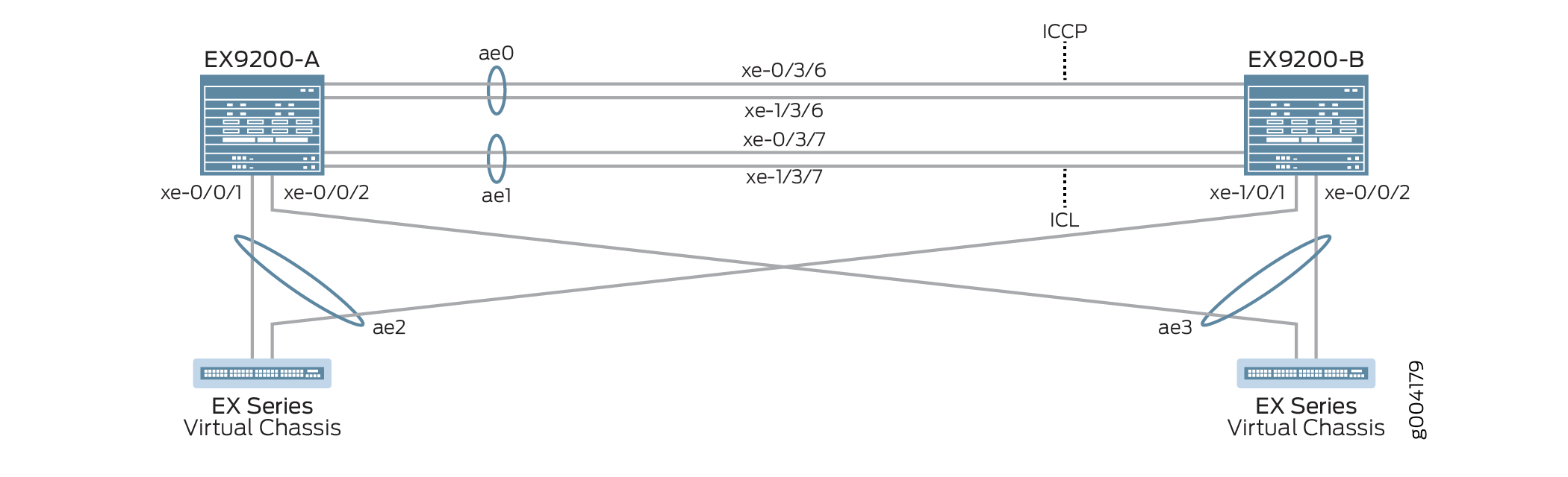 de topologia
A Tabela 2 detalha a topologia usada neste exemplo de configuração.
| Grupo de agregação de links multichassis | dehardware base | dohostname |
|---|---|---|
EX9200-A EX9200-B |
EX9200 EX9200 |
ae0 é configurada como uma interface Ethernet agregada, e é usada como um link ICCP, e as seguintes interfaces fazem parte do ae0: xe-0/3/6 e xe-1/3/6. ae1 é configurada como uma interface Ethernet agregada e é usada como um link ICL, e as seguintes interfaces fazem parte da ae1: xe-0/3/7 e xe-1/3/7. ae2 está configurada como um MC-LAG, e as seguintes interfaces fazem parte do ae2: xe-0/0/1 no Switch B e xe-1/0/1 no Switch A. ae3 está configurada como um MC-LAG, e a interface a seguir faz parte do ae3 tanto no Switch A quanto no Switch B: xe-0/0/2. |
Virtual Chassis Virtual Chassis |
Não aplicável. O Virtual Chassis é mostrado apenas para fins de ilustração. |
O Virtual Chassis está conectado aos dois switches EX9200 por meio de interfaces LAG. A configuração do Virtual Chassis não está incluída neste exemplo e só é mostrada para ilustrar uma topologia de amostra. |
Configuração
- Configuração rápida da CLI
- Configuração do MC-LAG no EX9200-A
- Configuração do MC-LAG no EX9200-B
- Resultados
Configuração rápida da CLI
Para configurar rapidamente este exemplo, copie os seguintes comandos, cole-os em um arquivo de texto, remova quaisquer quebras de linha, altere todos os detalhes necessários para combinar com a configuração da sua rede, copiar e colar os comandos na CLI no nível de [edit] hierarquia e, em seguida, entrar no commit modo de configuração.
EX9200-A
set system login user MCLAG_Admin uid 2000 set system login user MCLAG_Admin class super-user set system login user MCLAG_Admin authentication encrypted-password "$ABC123" set system static-host-mapping EX9200-A inet 10.92.76.2 set system static-host-mapping EX9200-B inet 10.92.76.4 set system services netconf ssh set system commit peers-synchronize set system commit peers EX9200-B user MCLAG_Admin set system commit peers EX9200-B authentication "$ABC123" set interfaces irb unit 100 family inet address 192.168.100.2/24 arp 192.168.100.3 l2-interface ae1 set interfaces irb unit 100 family inet address 192.168.100.2/24 arp 192.168.100.3 mac 28:8a:1c:e5:3b:f0 set interfaces irb unit 100 family inet address 192.168.100.2/24 vrrp-group 1 virtual-address 192.168.100.1 set interfaces irb unit 100 family inet address 192.168.100.2/24 vrrp-group 1 priority 150 set interfaces irb unit 100 family inet address 192.168.100.2/24 vrrp-group 1 accept-data set interfaces lo0 unit 0 family inet address 172.16.32.5/32 set routing-options static route 0.0.0.0/0 next-hop 10.92.77.254 set protocols ospf area 0.0.0.0 interface lo0.0 passive set protocols ospf area 0.0.0.0 interface ae0.0 set protocols lldp interface all set chassis aggregated-devices ethernet device-count 20 set groups MC_Config_Global set groups MC_Config_Global when peers EX9200-A set groups MC_Config_Global when peers EX9200-B set groups MC_Config_Global interfaces xe-0/3/6 ether-options 802.3ad ae0 set groups MC_Config_Global interfaces xe-1/3/6 ether-options 802.3ad ae0 set groups MC_Config_Global interfaces ae0 description "ICCP Layer 3 Link with 2 members,xe-0/3/6,xe-1/3/6" set groups MC_Config_Global interfaces ae0 aggregated-ether-options lacp active set groups MC_Config_Global interfaces ae0 aggregated-ether-options lacp periodic fast set groups MC_Config_Global interfaces ae0 aggregated-ether-options lacp system-id 00:01:02:03:04:05 set groups MC_Config_Global interfaces ae0 aggregated-ether-options lacp admin-key 0 set groups MC_Config_Global interfaces xe-0/3/7 ether-options 802.3ad ae1 set groups MC_Config_Global interfaces xe-1/3/7 ether-options 802.3ad ae1 set groups MC_Config_Global interfaces ae1 description "ICL Layer 2 link with 2 members,xe-0/3/7,1/3/7" set groups MC_Config_Global interfaces ae1 unit 0 family ethernet-switching interface-mode trunk set groups MC_Config_Global interfaces ae1 unit 0 family ethernet-switching vlan members all set groups MC_Config_Global interfaces ae1 vlan-tagging set groups MC_Config_Global interfaces ae1 aggregated-ether-options lacp active set groups MC_Config_Global interfaces ae1 aggregated-ether-options lacp periodic fast set groups MC_Config_Global interfaces ae1 aggregated-ether-options lacp system-id 00:01:02:03:04:06 set groups MC_Config_Global interfaces ae1 aggregated-ether-options lacp admin-key 1 set groups MC_Config_Global interfaces xe-0/0/1 ether-options 802.3ad ae2 set groups MC_Config_Global interfaces xe-1/0/1 ether-options 802.3ad ae2 set groups MC_Config_Global interfaces ae2 unit 0 description “MC-LAG interface with members xe-0/0/1,xe-1/0/1” set groups MC_Config_Global interfaces ae2 unit 0 family ethernet-switching interface-mode trunk set groups MC_Config_Global interfaces ae2 unit 0 family ethernet-switching vlan members all set groups MC_Config_Global interfaces ae2 aggregated-ether-options lacp active set groups MC_Config_Global interfaces ae2 aggregated-ether-options lacp periodic fast set groups MC_Config_Global interfaces ae2 aggregated-ether-options lacp system-id 00:01:02:03:04:07 set groups MC_Config_Global interfaces ae2 aggregated-ether-options lacp admin-key 2 set groups MC_Config_Global interfaces ae2 aggregated-ether-options mc-ae mc-ae-id 2 set groups MC_Config_Global interfaces ae2 aggregated-ether-options mc-ae redundancy-group 1 set groups MC_Config_Global interfaces ae2 aggregated-ether-options mc-ae mode active-active set groups MC_Config_Global interfaces ae2 aggregated-ether-options mc-ae init-delay-time 520 set groups MC_Config_Global interfaces ae2 aggregated-ether-options mc-ae events iccp-peer-down prefer-status-control-active set groups MC_Config_Global interfaces xe-0/0/2 ether-options 802.3ad ae3 set groups MC_Config_Global interfaces ae3 unit 0 description “MC-LAG interface with members xe-0/0/2 on both switches” set groups MC_Config_Global interfaces ae3 unit 0 family ethernet-switching interface-mode trunk set groups MC_Config_Global interfaces ae3 unit 0 family ethernet-switching vlan members all set groups MC_Config_Global interfaces ae3 aggregated-ether-options lacp active set groups MC_Config_Global interfaces ae3 aggregated-ether-options lacp periodic fast set groups MC_Config_Global interfaces ae3 aggregated-ether-options lacp system-id 00:01:02:03:04:08 set groups MC_Config_Global interfaces ae3 aggregated-ether-options lacp admin-key 3 set groups MC_Config_Global interfaces ae3 aggregated-ether-options mc-ae mc-ae-id 3 set groups MC_Config_Global interfaces ae3 aggregated-ether-options mc-ae redundancy-group 1 set groups MC_Config_Global interfaces ae3 aggregated-ether-options mc-ae mode active-active set groups MC_Config_Global interfaces ae3 aggregated-ether-options mc-ae init-delay-time 520 set groups MC_Config_Global interfaces ae3 aggregated-ether-options mc-ae events iccp-peer-down prefer-status-control-active set groups MC_Config_Global vlans v100 vlan-id 100 set groups MC_Config_Global vlans v100 l3-interface irb.100 set groups MC_Config_Global multi-chassis mc-lag consistency-check set groups MC_Config_Global protocols rstp interface ae2 set groups MC_Config_Global protocols rstp interface ae3 set groups MC_Config_Global protocols rstp bridge-priority 0 set groups MC_Config_Global protocols rstp system-id 00:01:02:03:04:09 set groups MC_Config_Global switch-options service-id 1 set groups MC_Config_Local set groups MC_Config_Local interfaces ae0 unit 0 family inet address 172.16.32.9/30 set groups MC_Config_Local interfaces ae2 aggregated-ether-options mc-ae chassis-id 0 set groups MC_Config_Local interfaces ae2 aggregated-ether-options mc-ae status-control active set groups MC_Config_Local interfaces ae3 aggregated-ether-options mc-ae chassis-id 0 set groups MC_Config_Local interfaces ae3 aggregated-ether-options mc-ae status-control active set groups MC_Config_Remote set groups MC_Config_Remote interfaces ae0 unit 0 family inet address 172.16.32.10/30 set groups MC_Config_Remote interfaces ae2 aggregated-ether-options mc-ae chassis-id 1 set groups MC_Config_Remote interfaces ae2 aggregated-ether-options mc-ae status-control standby set groups MC_Config_Remote interfaces ae3 aggregated-ether-options mc-ae chassis-id 1 set groups MC_Config_Remote interfaces ae3 aggregated-ether-options mc-ae status-control standby set interfaces ae2 unit 0 multi-chassis-protection 172.16.32.6 interface ae1 set interfaces ae3 unit 0 multi-chassis-protection 172.16.32.6 interface ae1 set protocols iccp local-ip-addr 172.16.32.5 set protocols iccp peer 172.16.32.6 session-establishment-hold-time 50 set protocols iccp peer 172.16.32.6 redundancy-group-id-list 1 set protocols iccp peer 172.16.32.6 backup-liveness-detection backup-peer-ip 10.92.76.4 set protocols iccp peer 172.16.32.6 liveness-detection minimum-interval 2000 set protocols iccp peer 172.16.32.6 liveness-detection multiplier 4 set multi-chassis multi-chassis-protection 172.16.32.6 interface ae1 set apply-groups [ MC_Config_Global MC_Config_Local MC_Config_Remote ]
EX9200-B
set system login user MCLAG_Admin uid 2000 set system login user MCLAG_Admin class super-user set system login user MCLAG_Admin authentication encrypted-password "$ABC123" set system static-host-mapping EX9200-A inet 10.92.76.2 set system static-host-mapping EX9200-B inet 10.92.76.4 set system services netconf ssh set system commit peers-synchronize set system commit peers EX9200-A user MCLAG_Admin set system commit peers EX9200-A authentication "$ABC123" set interfaces irb unit 100 family inet address 192.168.100.3/24 arp 192.168.100.2 l2-interface ae1 set interfaces irb unit 100 family inet address 192.168.100.3/24 arp 192.168.100.2 mac 28:8a:1c:e3:f7:f0 set interfaces irb unit 100 family inet address 192.168.100.3/24 vrrp-group 1 virtual-address 192.168.100.1 set interfaces irb unit 100 family inet address 192.168.100.3/24 vrrp-group 1 priority 100 set interfaces irb unit 100 family inet address 192.168.100.3/24 vrrp-group 1 accept-data set interfaces lo0 unit 0 family inet address 172.16.32.6/32 set routing-options static route 0.0.0.0/0 next-hop 10.92.77.254 set protocols ospf area 0.0.0.0 interface lo0 passive set protocols ospf area 0.0.0.0 interface ae0 set protocols lldp interface all set chassis aggregated-devices ethernet device-count 20 set interfaces ae2 unit 0 multi-chassis-protection 172.16.32.5 interface ae1 set interfaces ae3 unit 0 multi-chassis-protection 172.16.32.5 interface ae1 set protocols iccp local-ip-addr 172.16.32.6 set protocols iccp peer 172.16.32.5 session-establishment-hold-time 50 set protocols iccp peer 172.16.32.5 redundancy-group-id-list 1 set protocols iccp peer 172.16.32.5 backup-liveness-detection backup-peer-ip 10.92.76.2 set protocols iccp peer 172.16.32.5 liveness-detection minimum-interval 2000 set protocols iccp peer 172.16.32.5 liveness-detection multiplier 4 set apply-groups [ MC_Config_Global MC_Config_Local MC_Config_Remote ]
Configuração do MC-LAG no EX9200-A
Procedimento passo a passo
O exemplo a seguir exige que você navegue por vários níveis na hierarquia de configuração.
Crie uma conta de usuário para acessar o switch, juntamente com um identificador de usuário (UID), uma classe de login e uma senha.
[edit system] user@EX9200-A# set login user MCLAG_Admin uid 2000 user@EX9200-A# set login user MCLAG_Admin class super-user user@EX9200-A# set login user MCLAG_Admin authentication encrypted-password “$ABC123”
Mapeie o EX9200-A para 10,92,76,2 e EX9200-B para 10,92,76,4.
[edit system] user@EX9200-A# set static-host-mapping EX9200-A inet 10.92.76.2 user@EX9200-A# set static-host-mapping EX9200-B inet 10.92.76.4
Habilite o serviço NETCONF usando o SSH.
[edit system] user@EX9200-A# set services netconf ssh
Habilite a
peers-synchronizedeclaração para copiar e carregar a configuração MC-LAG do EX9200-A para EX9200-B por padrão.[edit system] user@EX9200-A# set commit peers-synchronize
Configure o nome de host, nomes de usuário e detalhes de autenticação para EX9200-B, o peer com o qual o EX9200-A estará sincronizando a configuração MC-LAG.
[edit system] user@EX9200-A# set commit peers EX9200-B user MCLAG_Admin user@EX9200-A# set commit peers EX9200-B user authentication “$ABC123”
Configure um IRB MC-LAG e configure o protocolo de resolução de endereços estático (ARP) nos pares de IRB MC-LAG para permitir que os protocolos de roteamento percorram a interface IRB.
[edit interfaces] user@EX9200-A# set irb unit 100 family inet address 192.168.100.2/24 arp 192.168.100.3 l2-interface ae1 user@EX9200-A# set irb unit 100 family inet address 192.168.100.2/24 arp 192.168.100.3 mac 28:8a:1c:e5:3b:f0
Habilite o VRRP nos MC-LAGs atribuindo um endereço IP virtual que é compartilhado entre cada switch no grupo VRRP e atribuindo um endereço IP individual para cada membro individual no grupo VRRP.
[edit interfaces] user@EX9200-A# set irb unit 100 family inet address 192.168.100.2/24 vrrp-group 1 virtual-address 192.168.100.1 user@EX9200-A# set irb unit 100 family inet address 192.168.100.2/24 vrrp-group 1 priority 150 user@EX9200-A# set irb unit 100 family inet address 192.168.100.2/24 vrrp-group 1 accept-data
Configure uma interface de loopback.
[edit interfaces] user@EX9200-A# set lo0 unit 0 family inet address 172.16.32.5/32
Configure um gateway padrão.
[edit routing-options] user@EX9200-A# set static route 0.0.0.0 next-hop 10.92.77.254
Configure uma área de OSPF que inclui a interface de loopback e a interface ICCP.
[edit protocols] user@EX9200-A# set ospf area 0.0.0.0 interface lo0 passive user@EX9200-A# set ospf area 0.0.0.0 interface ae0
Configure o protocolo de descoberta de camada de link para todas as interfaces.
[edit protocols] user@EX9200-A# set lldp interface all
Configure o número de interfaces Ethernet agregadas a serem criadas no EX9200-A.
[edit chassis] user@EX9200-A# set aggregated-devices ethernet device-count 20
Configure um grupo de configuração para uma configuração MC-LAG global que se aplica tanto ao EX9200-A quanto ao EX9200-B.
A configuração global é sincronizada entre EX9200-A e EX9200-B.
[edit groups] user@EX9200-A# set MC_Config_Global
Especifique os pares que aplicarão o grupo de configuração MC_Config_Global.
[edit groups] user@EX9200-A# set MC_Config_Global when peers EX9200-A user@EX9200-A# set MC_Config_Global when peers EX9200-B
Adicione interfaces de membros às interfaces Ethernet agregadas que serão usadas para a interface Inter-Chassis Control Protocol (ICCP).
[edit groups] user@EX9200-A# set MC_Config_Global interfaces xe-0/3/6 ether-options 802.3ad ae0 user@EX9200-A# set MC_Config_Global interfaces xe-1/3/6 ether-options 802.3ad ae0
Configure a interface Ethernet agregada (ae0) que será usada para a interface Inter-Chassis Control Protocol (ICCP).
Nota:Você estará configurando o endereço IP para ae0 em uma etapa posterior.
[edit groups] user@EX9200-A# set MC_Config_Global interfaces ae0 description "ICCP Layer 3 Link with 2 members,xe-0/3/6,xe-1/3/6"
Configure os parâmetros LACP em ae0.
[edit groups] user@EX9200-A# set MC_Config_Global interfaces ae0 aggregated-ether-options lacp active user@EX9200-A# set MC_Config_Global interfaces ae0 aggregated-ether-options lacp periodic fast
Configure a ID do sistema LACP em ae0.
[edit groups] user@EX9200-A# set MC_Config_Global interfaces ae0 aggregated-ether-options lacp system-id 00:01:02:03:04:05
Configure a chave administrativa lacp em ae0.
[edit groups] user@EX9200-A# set MC_Config_Global interfaces ae0 aggregated-ether-options lacp admin-key 0
Adicione interfaces de membros à interface Ethernet agregada (ae1) que será usada para a ICL.
[edit groups] user@EX9200-A# set MC_Config_Global interfaces xe-0/3/7 ether-options 802.3ad ae1 user@EX9200-A# set MC_Config_Global interfaces xe-1/3/7 ether-options 802.3ad ae1
Configure a interface Ethernet agregada que será usada para a ICL.
[edit groups] user@EX9200-A# set MC_Config_Global interfaces ae1 description "ICL Layer 2 link with 2 members,xe-0/3/7,1/3/7"
Configure ae1 como uma interface de Camada 2.
[edit groups] user@EX9200-A# set MC_Config_Global ae1 unit 0 family ethernet-switching interface-mode trunk user@EX9200-A# set MC_Config_Global ae1 unit 0 family ethernet-switching vlan members all
Habilite a recepção e a transmissão de quadros com tags VLAN 802.1Q na ae1.
[edit groups] user@EX9200-A# set MC_Config_Global interfaces ae1 vlan-tagging
Configure os parâmetros LACP em ae1.
[edit groups] user@EX9200-A# set MC_Config_Global interfaces ae1 aggregated-ether-options lacp active user@EX9200-A# set MC_Config_Global interfaces ae1 aggregated-ether-options lacp periodic fast
Configure a ID do sistema LACP em umae1.
[edit groups] user@EX9200-A# set MC_Config_Global interfaces ae1 aggregated-ether-options lacp system-id 00:01:02:03:04:06
Configure a chave administrativa do LACP na ae1.
[edit groups] user@EX9200-A# set MC_Config_Global interfaces ae1 aggregated-ether-options lacp admin-key 1
Adicione interfaces de membros à interface Ethernet agregada (ae2) que será usada como a interface MC-LAG.
[edit groups] user@EX9200-A# set MC_Config_Global interfaces xe-0/0/1 ether-options 802.3ad ae2 user@EX9200-A# set MC_Config_Global interfaces xe-1/0/1 ether-options 802.3ad ae2
Configure a interface Ethernet agregada (ae2) que será usada como uma interface MC-LAG.
[edit groups] user@EX9200-A# set MC_Config_Global interfaces ae2 description “MC-LAG interface with members xe-0/0/1,xe-1/0/1”
Configure o ae2 como uma interface de Camada 2.
[edit groups] user@EX9200-A# set MC_Config_Global interfaces ae2 unit 0 family ethernet-switching interface-mode trunk user@EX9200-A# set MC_Config_Global interfaces ae2 unit 0 family ethernet-switching vlan members all
Configure os parâmetros LACP em ae2.
[edit groups] user@EX9200-A# set MC_Config_Global interfaces ae2 aggregated-ether-options lacp active user@EX9200-A# set MC_Config_Global interfaces ae2 aggregated-ether-options lacp periodic fast
Configure o ID do sistema LACP em ae2.
[edit groups] user@EX9200-A# set MC_Config_Global interfaces ae2 aggregated-ether-options lacp system-id 00:01:02:03:04:07
Configure a chave administrativa lacp na ae2.
[edit groups] user@EX9200-A# set MC_Config_Global interfaces ae2 aggregated-ether-options lacp admin-key 2
Configure as propriedades da interface MC-AE em ae2.
[edit groups] user@EX9200-A# set MC_Config_Global interfaces ae2 aggregated-ether-options mc-ae mc-ae-id 2 user@EX9200-A# set MC_Config_Global interfaces ae2 aggregated-ether-options mc-ae redundancy-group 1
Especifique o modo de ae2 para estar ativo.
[edit groups] user@EX9200-A# set MC_Config_Global interfaces ae2 aggregated-ether-options mc-ae mode active-active
Especifique o tempo em segundos para atrasar a apresentação da interface MC-AE ao estado em alta após a reinicialização de um peer MC-LAG.
Ao atrasar a criação da interface até depois da convergência de protocolo, você pode evitar a perda de pacotes durante a recuperação de links e dispositivos com falha. Este exemplo de configuração de rede usa um tempo de atraso de 520 segundos. Esse tempo de atraso pode não ser ideal para sua rede e deve ser ajustado para atender aos seus requisitos de rede.
[edit groups] user@EX9200-A# set MC_Config_Global interfaces ae2 aggregated-ether-options mc-ae init-delay-time 520
Especifique se um peer do grupo MC-LAG cair, o peer configurado como ativo de controle de status se tornará o peer ativo.
[edit groups] user@EX9200-A# set MC_Config_Global interfaces ae2 aggregated-ether-options mc-ae events iccp-peer-down prefer-status-control-active
Adicione interfaces de membros à interface Ethernet agregada (ae3) que será usada como a interface MC-LAG.
Nota:O EX9200-B usa o mesmo nome de interface do xe-0/0/2.
[edit groups] user@EX9200-A# set MC_Config_Global interfaces xe-0/0/2 ether-options 802.3ad ae3
Configure a interface Ethernet agregada (ae3) que será usada como uma interface MC-LAG.
[edit groups] user@EX9200-A# set groups MC_Config_Global interfaces ae3 description “MC-LAG interface with members xe-0/0/2 on both switches”
Configure o ae3 como uma interface de Camada 2.
[edit groups] user@EX9200-A# set MC_Config_Global interfaces ae3 unit 0 family ethernet-switching interface-mode trunk user@EX9200-A# set MC_Config_Global interfaces ae3 unit 0 family ethernet-switching vlan members all
Configure os parâmetros LACP na ae3.
[edit groups] user@EX9200-A# set MC_Config_Global interfaces ae3 aggregated-ether-options lacp active user@EX9200-A# set MC_Config_Global interfaces ae3 aggregated-ether-options lacp periodic fast
Configure a ID do sistema LACP na ae3.
[edit groups] user@EX9200-A# set MC_Config_Global interfaces ae3 aggregated-ether-options lacp system-id 00:01:02:03:04:08
Configure a chave administrativa lacp na ae3.
[edit groups] user@EX9200-A# set MC_Config_Global interfaces ae3 aggregated-ether-options lacp admin-key 3
Configure as propriedades da interface MC-AE na ae3.
[edit groups] user@EX9200-A# set MC_Config_Global interfaces ae3 aggregated-ether-options mc-ae mc-ae-id 3 user@EX9200-A# set MC_Config_Global interfaces ae3 aggregated-ether-options mc-ae redundancy-group 1
Especifique o modo de ae3 para estar ativo.
[edit groups] user@EX9200-A# set MC_Config_Global interfaces ae3 aggregated-ether-options mc-ae mode active-active
Especifique o tempo em segundos para atrasar a apresentação da interface MC-AE ao estado em alta após a reinicialização de um peer MC-LAG.
Ao atrasar a criação da interface até depois da convergência de protocolo, você pode evitar a perda de pacotes durante a recuperação de links e dispositivos com falha. Este exemplo de configuração de rede usa um tempo de atraso de 520 segundos. Esse tempo de atraso pode não ser ideal para sua rede e deve ser ajustado para atender aos seus requisitos de rede.
[edit groups] user@EX9200-A# set MC_Config_Global interfaces ae3 aggregated-ether-options mc-ae init-delay-time 520
Especifique se um peer do grupo MC-LAG cair, o peer configurado como ativo de controle de status se tornará o peer ativo.
[edit groups] user@EX9200-A# set MC_Config_Global interfaces ae3 aggregated-ether-options mc-ae events iccp-peer-down prefer-status-control-active
Configure o VLAN 100 para conectar usuários finais.
[edit groups] user@EX9200-A# set MC_Config_Global vlans v100 vlan-id 100
Configure a interface VLAN roteada para VLAN 100.
[edit groups] user@EX9200-A# set MC_Config_Global vlans v100 l3-interface irb.100
Habilite a verificação de consistência.
[edit groups] user@EX9200-A# set MC_Config_Global multi-chassis mc-lag consistency-check
Habilite o protocolo Rapid Spanning Tree nas interfaces ae2 e ae3 (interfaces MC-LAG) para a prevenção opcional de loops.
[edit groups] user@EX9200-A# set MC_Config_Global protocols rstp interfaces ae2 user@EX9200-A# set MC_Config_Global protocols rstp interfaces ae3
Configure a prioridade da ponte RSTP.
Definir a prioridade da ponte para 0 tornará os nós MC-AE do EX9200-A e EX9200-B a melhor prioridade.
[edit groups] user@EX9200-A# set MC_Config_Global protocols rstp bridge-priority 0
Configure o valor do identificador do sistema RSTP.
[edit groups] user@EX9200-A# set MC_Config_Global protocols rstp system-id 00:01:02:03:04:09
Especifique a ID do serviço do switch.
O ID do serviço de switch é usado para sincronizar aplicativos, ARP e aprendizado MAC entre membros mc-LAG.
[edit groups] user@EX9200-A# set MC_Config_Global switch-options service-id 1
Configure um grupo de configuração para uma configuração MC-LAG que se aplica ao peer local.
[edit groups] user@EX9200-A# set MC_Config_Local
Configure a interface ICCP (ae0) como uma interface de Camada 3.
[edit groups] user@EX9200-A# set MC_Config_Local interfaces ae0 unit 0 family inet address 172.16.32.9/30
Especifique um ID de chassi exclusivo para o MC-LAG (ae2) do qual a interface Ethernet agregada pertence.
[edit groups] user@EX9200-A# set MC_Config_Local interfaces ae2 aggregated-ether-options mc-ae chassis-id 0
Especifique a configuração de controle de status de ae2 para estar ativo.
[edit groups] user@EX9200-A# set MC_Config_Local interfaces ae2 aggregated-ether-options mc-ae status-control active
Especifique um ID de chassi exclusivo para o MC-LAG (ae3) do qual a interface Ethernet agregada pertence.
[edit groups] user@EX9200-A# set MC_Config_Local interfaces ae3 aggregated-ether-options mc-ae chassis-id 0
Especifique a configuração de controle de status de ae3 para estar ativa.
[edit groups] user@EX9200-A# set MC_Config_Local interfaces ae3 aggregated-ether-options mc-ae status-control active
Configure um grupo de configuração para uma configuração MC-LAG que se aplica ao peer remoto.
[edit groups] user@EX9200-A# set MC_Config_Remote
Configure o ae0 como uma interface de Camada 3.
[edit groups] user@EX9200-A# set MC_Config_Remote interfaces ae0 unit 0 family inet address 172.16.32.10/30
Especifique um ID de chassi exclusivo para o MC-LAG (ae2) do qual a interface Ethernet agregada pertence.
[edit groups] user@EX9200-A# set MC_Config_Remote interfaces ae2 aggregated-ether-options mc-ae chassis-id 1
Especifique a configuração de controle de status de ae2 para ficar em espera.
[edit groups] user@EX9200-A# set MC_Config_Remote interfaces ae2 aggregated-ether-options mc-ae status-control standby
Especifique um ID de chassi exclusivo para o MC-LAG (ae3) do qual a interface Ethernet agregada pertence.
[edit groups] user@EX9200-A# set MC_Config_Remote interfaces ae3 aggregated-ether-options mc-ae chassis-id 1
Especifique a configuração de controle de status de ae3 para ficar em espera.
[edit interfaces] user@EX9200-A# set MC_Config_Remote interfaces ae3 aggregated-ether-options mc-ae status-control standby
Especifique se um peer do grupo MC-LAG cair, o peer configurado como ativo de controle de status se tornará o peer ativo.
[edit interfaces] user@EX9200-A# set MC_Config_Remote interfaces ae3 aggregated-ether-options mc-ae events iccp-peer-down prefer-status-control-standby
Habilite a proteção de enlaces entre os dois pares MC-LAG.
Atribua interface ae1 para atuar como ICL para proteger as interfaces MC-AE, ae2 e ae3, em caso de falha.
[edit interfaces] user@EX9200-A# set ae2 unit 0 multi-chassis-protection 172.16.32.6 interface ae1
user@EX9200-A# set ae3 unit 0 multi-chassis-protection 172.16.32.6 interface ae1
Especifique o endereço IP local da interface ICCP.
[edit protocols] user@EX9200-A# set iccp local-ip-addr 172.16.32.5
Configure o tempo de espera do estabelecimento de sessão para que o ICCP se conecte mais rapidamente.
Nota:Recomendamos 50 segundos conforme o estabelecimento da sessão mantém o valor do tempo.
[edit protocols] user@EX9200-A# set iccp peer 172.16.32.6 session-establishment-hold-time 50 user@EX9200-A# set iccp peer 172.16.32.6 redundancy-group-id-list 1 user@EX9200-A# set iccp peer 172.16.32.6 backup-liveness-detection backup-peer-ip 10.92.76.4
Para habilitar o BFD para ICCP, configure o intervalo mínimo de recebimento.
Recomendamos um valor mínimo de intervalo de recebimento de 6 segundos.
[edit protocols] user@EX9200-A# set iccp peer 172.16.32.6 liveness-detection minimum-interval 2000 user@EX9200-A# set iccp peer 172.16.32.6 liveness-detection multiplier 4
Aplique os grupos configurados anteriormente para que a configuração do Junos herdará as declarações dos grupos de configuração de MC_Config_Global, MC_Config_Local e MC_Config_Remote.
[edit] user@EX9200-A# set apply-groups [ MC_Config_Global MC_Config_Local MC_Config_Remote ]
Configuração do MC-LAG no EX9200-B
Procedimento passo a passo
O exemplo a seguir exige que você navegue por vários níveis na hierarquia de configuração.
Crie uma conta de usuário para acessar o switch, juntamente com um identificador de usuário (UID), uma classe de login e uma senha.
[edit system] user@EX9200-A# set login user MCLAG_Admin uid 2000 user@EX9200-B# set login user MCLAG_Admin class super-user user@EX9200-B# set login user MCLAG_Admin authentication encrypted-password “$ABC123”
Mapeie o EX9200-A para 10,92,76,2 e EX9200-B para 10,92,76,4.
[edit system] user@EX9200-B# set static-host-mapping EX9200-A inet 10.92.76.2 user@EX9200-B# set static-host-mapping EX9200-B inet 10.92.76.4
Habilite o serviço NETCONF usando o SSH.
[edit system] user@EX9200-B# set services netconf ssh
Habilite a
peers-synchronizedeclaração para copiar e carregar a configuração MC-LAG do EX9200-B para EX9200-A por padrão.[edit system] user@EX9200-B# set commit peers-synchronize
Configure o nome de host, nomes de usuário e detalhes de autenticação para EX9200-A, o peer com o qual o EX9200-B estará sincronizando a configuração MC-LAG.
[edit system] user@EX9200-B# set commit peers EX9200-A user MCLAG_Admin user@EX9200-A# set commit peers EX9200-A authentication "$ABC123"
Configure um IRB MC-LAG e configure o protocolo de resolução de endereços estático (ARP) nos pares de IRB MC-LAG para permitir que os protocolos de roteamento percorram a interface IRB.
[edit interfaces] user@EX9200-B# set irb unit 100 family inet address 192.168.100.3/24 arp 192.168.100.2 l2-interface ae1 user@EX9200-B# set irb unit 100 family inet address 192.168.100.3/24 arp 192.168.100.2 mac 28:8a:1c:e3:f7:f0
Habilite o VRRP nos MC-LAGs atribuindo um endereço IP virtual que é compartilhado entre cada switch no grupo VRRP e atribuindo um endereço IP individual para cada membro individual no grupo VRRP.
[edit interfaces] user@EX9200-B# set irb unit 100 family inet address 192.168.100.3/24 vrrp-group 1 virtual-address 192.168.100.1 user@EX9200-B# set irb unit 100 family inet address 192.168.100.3/24 vrrp-group 1 priority 100 user@EX9200-B# set irb unit 100 family inet address 192.168.100.3/24 vrrp-group 1 accept-data
Configure uma interface de loopback.
[edit interfaces] user@EX9200-B# set lo0 unit 0 family inet address 172.16.32.6/32
Configure um gateway padrão.
[edit routing-options] user@EX9200-B# set static route 0.0.0.0 next-hop 10.92.77.254
Configure uma área de OSPF que inclui a interface de loopback e a interface ICCP.
[edit protocols] user@EX9200-B# set ospf area 0.0.0.0 interface lo0 passive user@EX9200-B# set ospf area 0.0.0.0 interface ae0
Configure o protocolo de descoberta de camada de link para todas as interfaces.
[edit protocols] user@EX9200-B# set lldp interface all
Configure o número de interfaces Ethernet agregadas a serem criadas no EX9200-B.
[edit chassis] user@EX9200-B# set aggregated-devices ethernet device-count 20
Habilite a proteção de enlaces entre os dois pares MC-LAG.
Atribua interface ae1 para atuar como ICL para proteger as interfaces MC-AE, ae2 e ae3, em caso de falha.
[edit interfaces] user@EX9200-B# set ae2 unit 0 multi-chassis-protection 172.16.32.5 interface ae1 user@EX9200-B# set ae3 unit 0 multi-chassis-protection 172.16.32.5 interface ae1
Especifique o endereço IP local da interface ICCP.
[edit protocols] user@EX9200-B# set iccp local-ip-addr 172.16.32.6
Configure o tempo de espera do estabelecimento de sessão para que o ICCP se conecte mais rapidamente.
Nota:Recomendamos 50 segundos conforme o estabelecimento da sessão mantém o valor do tempo.
[edit protocols] user@EX9200-B# set iccp peer 172.16.32.5 session-establishment-hold-time 50 user@EX9200-B# set iccp peer 172.16.32.5 redundancy-group-id-list 1 user@EX9200-B# set iccp peer 172.16.32.5 backup-liveness-detection backup-peer-ip 10.92.76.2
Para habilitar o BFD para ICCP, configure o intervalo mínimo de recebimento.
Recomendamos um valor mínimo de intervalo de recebimento de 6 segundos.
[edit protocols] user@EX9200-B# set iccp peer 172.16.32.5 liveness-detection minimum-interval 2000 user@EX9200-B# set iccp peer 172.16.32.5 liveness-detection multiplier 4
Aplique os grupos configurados anteriormente para que a configuração do Junos herdará as declarações dos grupos de configuração de MC_Config_Global, MC_Config_Local e MC_Config_Remote.
[edit] user@EX9200-B# set apply-groups [ MC_Config_Global MC_Config_Local MC_Config_Remote ]
Resultados
Exibir os resultados da configuração no EX9200-A antes de confirmar a configuração.
user@EX9200-A# show system services
netconf {
ssh;
}
user@EX9200-A# show system commit
peers-synchronize;
peers {
EX9200-B {
user MCLAG_Admin;
authentication "$ABC123”;
}
}
}
user@EX9200-A# show interfaces
ae2 {
unit 0 {
multi-chassis-protection 172.16.32.6 {
interface ae1;
}
}
}
ae3 {
unit 0 {
multi-chassis-protection 172.16.32.6 {
interface ae1;
}
}
}
irb {
unit 100 {
family inet {
address 192.168.100.2/24 {
arp 192.168.100.3 l2-interface ae1.0 mac 28:8a:1c:e5:3b:f0;
vrrp-group 1 {
virtual-address 192.168.100.1;
priority 150;
accept-data;
}
}
}
}
}
lo0 {
unit 0 {
family inet {
address 172.16.32.5/32;
}
}
}
user@EX9200-A# show routing-options
static {
route 0.0.0.0/0 next-hop 10.92.77.254;
}
user@EX9200-A# show protocols
ospf {
area 0.0.0.0 {
interface lo0.0 {
passive;
}
interface ae0.0;
}
}
iccp {
local-ip-addr 172.16.32.5;
peer 172.16.32.6 {
session-establishment-hold-time 50;
redundancy-group-id-list 1;
backup-liveness-detection {
backup-peer-ip 10.92.76.4;
}
liveness-detection {
minimum-interval 2000;
multiplier 4;
}
}
}
lldp {
interface all;
}
user@EX9200-A# show chassis
aggregated-devices {
ethernet {
device-count 20;
}
}
user@EX9200-A# show groups MC_Config_Global
when {
peers [ EX9200-A EX9200-B ];
}
interfaces {
xe-0/3/6 {
ether-options {
802.3ad ae0;
}
}
xe-1/3/6 {
ether-options {
802.3ad ae0;
}
}
ae0 {
description "ICCP Layer 3 Link with 2 members,xe-0/3/6,xe-1/3/6";
aggregated-ether-options {
lacp {
active;
periodic fast;
system-id 00:01:02:03:04:05;
admin-key 0;
}
}
}
xe-0/3/7 {
ether-options {
802.3ad ae1;
}
}
xe-1/3/7 {
ether-options {
802.3ad ae1;
}
}
ae1 {
description "ICL Layer 2 link with 2 members,xe-0/3/7,1/3/7";
vlan-tagging;
aggregated-ether-options {
lacp {
active;
periodic fast;
system-id 00:01:02:03:04:06;
admin-key 1;
}
}
unit 0 {
family ethernet-switching {
interface-mode trunk;
vlan {
members all;
}
}
}
}
xe-0/0/1 {
ether-options {
802.3ad ae2;
}
}
xe-1/0/1 {
ether-options {
802.3ad ae2;
}
}
ae2 {
description "MC-LAG interface with members xe-0/0/1,xe-1/0/1";
aggregated-ether-options {
lacp {
active;
periodic fast;
system-id 00:01:02:03:04:07;
admin-key 2;
}
mc-ae {
mc-ae-id 2;
redundancy-group 1;
mode active-active;
init-delay-time 520;
events {
iccp-peer-down {
prefer-status-control-active;
}
}
}
}
unit 0 {
family ethernet-switching {
interface-mode trunk;
vlan {
members all;
}
}
}
}
xe-0/0/2 {
ether-options {
802.3ad ae3;
}
}
ae3 {
description “MC-LAG interface with members xe-0/0/2 on both switches”
aggregated-ether-options {
lacp {
active;
periodic fast;
system-id 00:01:02:03:04:08;
admin-key 3;
}
mc-ae {
mc-ae-id 3;
redundancy-group 1;
mode active-active;
init-delay-time 520;
events {
iccp-peer-down {
prefer-status-control-active;
}
}
}
}
unit 0 {
family ethernet-switching {
interface-mode trunk;
vlan {
members all;
}
}
}
}
}
multi-chassis {
mc-lag {
consistency-check;
}
}
protocols {
rstp {
bridge-priority 0;
system-id 00:01:02:03:04:09;
interface ae2;
interface ae3;
}
}
switch-options {
service-id 1;
}
vlans {
v100 {
vlan-id 100;
l3-interface irb.100;
}
}
user@EX9200-A# show groups MC_Config_Local
interfaces {
ae0 {
unit 0 {
family inet {
address 172.16.32.9/30;
}
}
}
ae2 {
aggregated-ether-options {
mc-ae {
chassis-id 0;
status-control active;
}
}
}
ae3 {
aggregated-ether-options {
mc-ae {
chassis-id 0;
status-control active;
}
}
}
}
user@EX9200-A# show groups MC_Config_Remote
interfaces {
ae0 {
unit 0 {
family inet {
address 172.16.32.10/30;
}
}
}
ae2 {
aggregated-ether-options {
mc-ae {
chassis-id 1;
status-control standby;
}
}
}
ae3 {
aggregated-ether-options {
mc-ae {
chassis-id 1;
status-control standby;
}
}
}
}
user@EX9200-A# show apply-groups apply-groups [ MC_Config_Global MC_Config_Local MC_Config_Remote ];
Exibir os resultados da configuração no EX9200-B antes de confirmar a configuração.
user@EX9200-B# show system services
netconf {
ssh;
}
user@EX9200-B# show system commit
peers-synchronize;
peers {
EX9200-A {
user MCLAG_Admin;
authentication "$ABC123”;
}
}
user@EX9200-B# show interfaces
ae2 {
unit 0 {
multi-chassis-protection 172.16.32.5 {
interface ae1;
}
}
}
ae3 {
unit 0 {
multi-chassis-protection 172.16.32.5 {
interface ae1;
}
}
}
irb {
unit 100 {
family inet {
address 192.168.100.3/24 {
arp 192.168.100.2 l2-interface ae1.0 mac 28:8a:1c:e3:f7:f0;
vrrp-group 1 {
virtual-address 192.168.100.1;
priority 100;
accept-data;
}
}
}
}
}
lo0 {
unit 0 {
family inet {
address 172.16.32.6/32;
}
}
}
user@EX9200-B# show routing-options
static {
route 0.0.0.0/0 next-hop 10.92.77.254;
}
user@EX9200-B# show protocols
ospf {
area 0.0.0.0 {
interface lo0.0 {
passive;
}
interface ae0.0;
}
}
iccp {
local-ip-addr 172.16.32.6;
peer 172.16.32.5 {
session-establishment-hold-time 50;
redundancy-group-id-list 1;
backup-liveness-detection {
backup-peer-ip 10.92.76.2;
}
liveness-detection {
minimum-interval 2000;
multiplier 4;
}
}
}
lldp {
interface all;
}
user@EX9200-B# show chassis
aggregated-devices {
ethernet {
device-count 20;
}
}
user@EX9200-B# show apply-groups [ MC_Config_Global MC_Config_Local MC_Config_Remote ];
Verificação
- Verificação do ICCP no MC-LAG
- Verificação do LACP no MC-LAG
- Verificação de interfaces de ethernet agregadas no MC-LAG
- Verificação do aprendizado MAC no MC-LAG
- Verificação do VRRP no MC-LAG
- Verificação do OSPF no MC-LAG
- Verificação da consistência da configuração aprovada
- Verificando o status de verificação da consistência da configuração para a configuração global
- Verificando o status de verificação da consistência da configuração para o link de controle de interchassis
- Verificando o status de verificação da consistência da configuração para as interfaces MC-LAG
- Verificando o status de verificação da consistência da configuração para a configuração da VLAN
- Verificando o status de verificação da consistência da configuração para VRRP
Verificação do ICCP no MC-LAG
Propósito
Verifique se o ICCP está sendo executado em cada dispositivo no MC-LAG.
Ação
Verifique se o ICCP está sendo executado no EX9200-A.
user@EX92000-A> show iccp Redundancy Group Information for peer 172.16.32.6 TCP Connection : Established Liveliness Detection : Up Backup liveness peer status: Up Redundancy Group ID Status 1 Up Client Application: lacpd Redundancy Group IDs Joined: 1 Client Application: l2ald_iccpd_client Redundancy Group IDs Joined: 1 Client Application: mclag_cfgchkd Redundancy Group IDs Joined: 1Verifique se o ICCP está sendo executado no EX9200-B.
user@EX9200-B> show iccp Redundancy Group Information for peer 172.16.32.5 TCP Connection : Established Liveliness Detection : Up Backup liveness peer status: Up Redundancy Group ID Status 1 Up Client Application: lacpd Redundancy Group IDs Joined: 1 Client Application: l2ald_iccpd_client Redundancy Group IDs Joined: 1 Client Application: mclag_cfgchkd Redundancy Group IDs Joined: 1
Significado
Essa saída mostra que a conexão de TCP entre os pares que hospedam o MC-LAG está ativa, a detecção de liveness está ativa, o status de peer de liveness de backup está em alta e o LACPD, MCLAG_CFGCHKD e L2ALD _ICCP_CLIENT aplicativos de clientes estão sendo executados.
Verificação do LACP no MC-LAG
Propósito
Verifique se o LACP está funcionando corretamente em cada dispositivo no MC-LAG.
Ação
Verifique se as interfaces LACP estão ativas no EX9200-A.
user@EX9200-A> show lacp interfaces Aggregated interface: ae0 LACP state: Role Exp Def Dist Col Syn Aggr Timeout Activity xe-0/3/6 Actor No No Yes Yes Yes Yes Fast Active xe-0/3/6 Partner No No Yes Yes Yes Yes Fast Active xe-1/3/6 Actor No No Yes Yes Yes Yes Fast Active xe-1/3/6 Partner No No Yes Yes Yes Yes Fast Active LACP protocol: Receive State Transmit State Mux State xe-0/3/6 Current Fast periodic Collecting distributing xe-1/3/6 Current Fast periodic Collecting distributing Aggregated interface: ae1 LACP state: Role Exp Def Dist Col Syn Aggr Timeout Activity xe-0/3/7 Actor No No Yes Yes Yes Yes Fast Active xe-0/3/7 Partner No No Yes Yes Yes Yes Fast Active xe-1/3/7 Actor No No Yes Yes Yes Yes Fast Active xe-1/3/7 Partner No No Yes Yes Yes Yes Fast Active LACP protocol: Receive State Transmit State Mux State xe-0/3/7 Current Fast periodic Collecting distributing xe-1/3/7 Current Fast periodic Collecting distributing Aggregated interface: ae2 LACP state: Role Exp Def Dist Col Syn Aggr Timeout Activity xe-0/0/1 Actor No Yes No No No Yes Fast Active xe-0/0/1 Partner No Yes No No No Yes Fast Passive LACP protocol: Receive State Transmit State Mux State xe-0/0/1 Current Fast periodic Collecting distributing xe-1/0/1 Port disabled Fast periodic Collecting distributing Aggregated interface: ae3 LACP state: Role Exp Def Dist Col Syn Aggr Timeout Activity xe-0/0/2 Actor No Yes No No No Yes Fast Active xe-0/0/2 Partner No Yes No No No Yes Fast Passive LACP protocol: Receive State Transmit State Mux State xe-0/0/2 Current Fast periodic Collecting distributingVerifique se as interfaces LACP estão ativas no EX9200-B.
user@EX9200-B> show lacp interfaces Aggregated interface: ae0 LACP state: Role Exp Def Dist Col Syn Aggr Timeout Activity xe-0/3/6 Actor No No Yes Yes Yes Yes Fast Active xe-0/3/6 Partner No No Yes Yes Yes Yes Fast Active xe-1/3/6 Actor No No Yes Yes Yes Yes Fast Active xe-1/3/6 Partner No No Yes Yes Yes Yes Fast Active LACP protocol: Receive State Transmit State Mux State xe-0/3/6 Current Fast periodic Collecting distributing xe-1/3/6 Current Fast periodic Collecting distributing Aggregated interface: ae1 LACP state: Role Exp Def Dist Col Syn Aggr Timeout Activity xe-0/3/7 Actor No No Yes Yes Yes Yes Fast Active xe-0/3/7 Partner No No Yes Yes Yes Yes Fast Active xe-1/3/7 Actor No No Yes Yes Yes Yes Fast Active xe-1/3/7 Partner No No Yes Yes Yes Yes Fast Active LACP protocol: Receive State Transmit State Mux State xe-0/3/7 Current Fast periodic Collecting distributing xe-1/3/7 Current Fast periodic Collecting distributing Aggregated interface: ae2 LACP state: Role Exp Def Dist Col Syn Aggr Timeout Activity xe-1/0/1 Actor No Yes No No No Yes Fast Active xe-1/0/1 Partner No Yes No No No Yes Fast Passive LACP protocol: Receive State Transmit State Mux State xe-0/0/1 Current Fast periodic Collecting distributing xe-1/0/1 Current Fast periodic Collecting distributing Aggregated interface: ae3 LACP state: Role Exp Def Dist Col Syn Aggr Timeout Activity xe-0/0/2 Actor No Yes No No No Yes Fast Active xe-0/0/2 Partner No Yes No No No Yes Fast Passive LACP protocol: Receive State Transmit State Mux State xe-0/0/2 Current Fast periodic Collecting distributing
Significado
Essa saída significa que ambos os dispositivos e todas as interfaces relacionadas estão participando adequadamente das negociações de LACP.
Verificação de interfaces de ethernet agregadas no MC-LAG
Propósito
Verifique se todas as interfaces ae estão configuradas corretamente no MC-LAG.
Ação
Verifique as interfaces ae no EX9200-A.
user@EX9200-A> show interfaces mc-ae Member Link : ae2 Current State Machine's State: mcae active state Configuration Error Status : No Error Local Status : active Local State : up Peer Status : active Peer State : up Logical Interface : ae2.0 Topology Type : bridge Local State : up Peer State : up Peer Ip/MCP/State : 172.16.32.6 ae1.0 up Member Link : ae3 Current State Machine's State: mcae active state Configuration Error Status : No Error Local Status : active Local State : up Peer Status : active Peer State : up Logical Interface : ae3.0 Topology Type : bridge Local State : up Peer State : up Peer Ip/MCP/State : 172.16.32.6 ae1.0 upVerifique as interfaces ae no EX9200-B.
user@EX9200-B> show interface mc-ae Member Link : ae2 Current State Machine's State: mcae active state Configuration Error Status : No Error Local Status : active Local State : up Peer Status : active Peer State : up Logical Interface : ae2.0 Topology Type : bridge Local State : up Peer State : up Peer Ip/MCP/State : 172.16.32.5 ae1.0 up Member Link : ae3 Current State Machine's State: mcae active state Configuration Error Status : No Error Local Status : active Local State : down Peer Status : active Peer State : down Logical Interface : ae3.0 Topology Type : bridge Local State : up Peer State : up Peer Ip/MCP/State : 172.16.32.5 ae1.0 up
Significado
Essa saída significa que as interfaces mc-ae em cada dispositivo estão ativas.
Verificação do aprendizado MAC no MC-LAG
Propósito
Verifique se o aprendizado MAC entre dispositivos está acontecendo no MC-LAG.
Ação
Mostre a tabela de comutação Ethernet no EX9200-A.
user@EX9200-A> show ethernet-switching table MAC flags (S - static MAC, D - dynamic MAC, L - locally learned, P - Persistent static, C - Control MAC SE - statistics enabled, NM - non configured MAC, R - remote PE MAC, O - ovsdb MAC) Ethernet switching table : 2 entries, 2 learned Routing instance : EVPN-2 Vlan MAC MAC Age Logical NH RTR name address flags interface Index ID v100 10:0e:7e:b1:01:80 DC - pip-7.040010000000 1048580 1048580 v100 4c:96:14:e7:fd:81 DRC - ae10.200 0 0Mostre a tabela de comutação Ethernet no EX9200-B.
user@EX9200-B> show ethernet-switching table MAC flags (S - static MAC, D - dynamic MAC, L - locally learned, P - Persistent static, C - Control MAC SE - statistics enabled, NM - non configured MAC, R - remote PE MAC, O - ovsdb MAC) Ethernet switching table : 2 entries, 2 learned Routing instance : EVPN-2 Vlan name MAC address MAC flags Age Logical interface NH Index RTR ID v100 10:0e:7e:b1:01:80 DC - pip-7.060010000000 1048581 1048580 v100 4c:96:14:e7:fd:81 D - ae10.200 0 0
Significado
Essa saída significa que os endereços MAC são devidamente aprendidos dentro das VLANs compartilhadas definidas no MC-LAG.
Verificação do VRRP no MC-LAG
Propósito
Verifique se o VRRP está ativo entre os dispositivos no MC-LAG.
Ação
Confirme que o VRRP está ativo no EX9200-A.
user@EX9200-A> show vrrp Interface State Group VR state VR Mode Timer Type Address irb.100 up 1 master Active A 0.789 lcl 192.168.100.2 vip 192.168.100.1Neste exemplo, o Switch A é o membro VRRP principal.
Confirme que o VRRP está ativo no EX9200-B.
user@EX9200-B> show vrrp Interface State Group VR state VR Mode Timer Type Address irb.100 up 1 backup Active D 2.887 lcl 192.168.100.3 vip 192.168.100.1 mas 192.168.100.2Neste exemplo, o Switch B é o membro VRRP de backup.
Significado
Essa saída significa que o VRRP está funcionando corretamente.
Verificação do OSPF no MC-LAG
Propósito
Verifique se o OSPF está funcionando corretamente com o MC-LAG.
Ação
Mostre aos vizinhos do OSPF no EX9200-A.
user@EX9200-A> show ospf neighbor Address Interface State ID Pri Dead 172.16.32.10 ae0.0 Full 172.16.32.6 128 33
Mostre a tabela de roteamento OSPF no EX9200-A.
user@EX9200-A> show ospf route Topology default Route Table: Prefix Path Route NH Metric NextHop Nexthop Type Type Type Interface Address/LSP 172.16.32.6 Intra Router IP 1 ae0.0 172.16.32.10 172.16.32.5/32 Intra Network IP 0 lo0.0 172.16.32.6/32 Intra Network IP 1 ae0.0 172.16.32.10 172.16.32.8/30 Intra Network IP 1 ae0.0Mostre aos vizinhos do OSPF no EX9200-B.
user@EX9200-B> show ospf neighbor Address Interface State ID Pri Dead 172.16.32.9 ae0.0 Full 172.16.32.5 128 31
Mostre a tabela de roteamento OSPF no EX9200-B.
user@EX9200-B> show ospf route Topology default Route Table: Prefix Path Route NH Metric NextHop Nexthop Type Type Type Interface Address/LSP 172.16.32.5 Intra Router IP 1 ae0.0 172.16.32.9 172.16.32.5/32 Intra Network IP 1 ae0.0 172.16.32.9 172.16.32.6/32 Intra Network IP 0 lo0.0 172.16.32.8/30 Intra Network IP 1 ae0.0
Significado
A saída mostra que os dispositivos vizinhos são totalmente adjacentes.
Verificação da consistência da configuração aprovada
Propósito
Veja a lista de parâmetros de MC-LAG comprometidos que são verificados quanto a inconsistências, o requisito de consistência (idêntico ou único), o nível de aplicação (obrigatório ou desejado) e o resultado da verificação da consistência da configuração. Os resultados são aprovados ou reprovados.
Ação
Mostre a lista de parâmetros de MC-LAG comprometidos que passaram ou falharam na verificação da consistência da configuração no EX9200-A.
user@EX9200-A> show multi-chassis mc-lag configuration-consistency Configuration Item Enforcement Level Local Value Peer Value Result ------------------ ----------------- ----------- ---------- ------- ICL interface Mandatory ae1 ae1 PASS rstp-bridge-priority Desirable 0 0 PASS service-id Mandatory 1 1 PASS session-establishment-hold-time Mandatory 300 300 PASS local-ip-addr Mandatory 172.16.32.5 172.16.32.6 PASS backup-liveness-detection Mandatory 10.92.76.4 10.92.76.2 PASS iccp/bfd multiplier Mandatory 4 4 PASS bfd minimum-interval Mandatory 2000 2000 PASS session-establishment-hold-time Mandatory 50 50 PASS Local Physical Interface:ae2 Peer Physical Interface :ae2 Configuration Item Enforcement Level Local Value Peer Value Result ------------------ ----------------- ----------- ---------- ------- lacp admin-key Mandatory 2 2 PASS lacp system-id Mandatory 00:01:02:03:04:07 00:01:02:03:04:07 PASS lacp periodic Mandatory 0 0 PASS lacp mode Mandatory 0 0 PASS prefer-status-control-active Desirable TRUE -- PASS mcae status-control Mandatory standby active PASS mcae deployment mode Mandatory active-active active-active PASS mcae chassis-id Mandatory 0 1 PASS mcae redundancy-group Mandatory 1 1 PASS Local Logical Interface:ae2.0 Peer Logical Interface :ae2.0 Configuration Item Enforcement Level Local Value Peer Value Result ------------------ ----------------- ----------- ---------- ------- vlan membership Mandatory 100 100 PASS interface-mode Mandatory trunk trunk PASS Local Physical Interface:ae3 Peer Physical Interface :ae3 Configuration Item Enforcement Level Local Value Peer Value Result ------------------ ----------------- ----------- ---------- ------- lacp admin-key Mandatory 3 3 PASS lacp system-id Mandatory 00:01:02:03:04:08 00:01:02:03:04:08 PASS lacp periodic Mandatory 0 0 PASS lacp mode Mandatory 0 0 PASS prefer-status-control-active Desirable TRUE -- PASS mcae status-control Mandatory standby active PASS mcae deployment mode Mandatory active-active active-active PASS mcae chassis-id Mandatory 0 1 PASS mcae redundancy-group Mandatory 1 1 PASS Local Logical Interface:ae3.0 Peer Logical Interface :ae3.0 Configuration Item Enforcement Level Local Value Peer Value Result ------------------ ----------------- ----------- ---------- ------- vlan membership Mandatory 100 100 PASS interface-mode Mandatory trunk trunk PASS Local VLAN:v100 Peer VLAN :v100 Local IRB:irb.100 Peer IRB :irb.100 Configuration Item Enforcement Level Local Value Peer Value Result ------------------ ----------------- ----------- ---------- ------- vrrp-group id Mandatory 1 1 PASS ipv4 address Mandatory 192.168.100.2/24 192.168.100.3/24 PASSMostre a lista de parâmetros de MC-LAG comprometidos que passaram ou falharam na verificação da consistência da configuração no EX9200-B.
user@EX9200-B> show multi-chassis mc-lag configuration-consistency Configuration Item Enforcement Level Local Value Peer Value Result ------------------ ----------------- ----------- ---------- ------- ICL interface Mandatory ae1 ae1 PASS rstp-bridge-priority Desirable 0 0 PASS service-id Mandatory 1 1 PASS session-establishment-hold-time Mandatory 300 300 PASS local-ip-addr Mandatory 172.16.32.6 172.16.32.5 PASS backup-liveness-detection Mandatory 10.92.76.2 10.92.76.4 PASS iccp/bfd multiplier Mandatory 4 4 PASS bfd minimum-interval Mandatory 2000 2000 PASS session-establishment-hold-time Mandatory 50 50 PASS Local Physical Interface:ae2 Peer Physical Interface :ae2 Configuration Item Enforcement Level Local Value Peer Value Result ------------------ ----------------- ----------- ---------- ------- lacp admin-key Mandatory 2 2 PASS lacp system-id Mandatory 00:01:02:03:04:07 00:01:02:03:04:07 PASS lacp periodic Mandatory 0 0 PASS lacp mode Mandatory 0 0 PASS mcae status-control Mandatory active standby PASS mcae deployment mode Mandatory active-active active-active PASS mcae chassis-id Mandatory 1 0 PASS mcae redundancy-group Mandatory 1 1 PASS prefer-status-control-active Desirable -- TRUE PASS Local Logical Interface:ae2.0 Peer Logical Interface :ae2.0 Configuration Item Enforcement Level Local Value Peer Value Result ------------------ ----------------- ----------- ---------- ------- vlan membership Mandatory 100 100 PASS interface-mode Mandatory trunk trunk PASS Local Physical Interface:ae3 Peer Physical Interface :ae3 Configuration Item Enforcement Level Local Value Peer Value Result ------------------ ----------------- ----------- ---------- ------- lacp admin-key Mandatory 3 3 PASS lacp system-id Mandatory 00:01:02:03:04:08 00:01:02:03:04:08 PASS lacp periodic Mandatory 0 0 PASS lacp mode Mandatory 0 0 PASS mcae status-control Mandatory active standby PASS mcae deployment mode Mandatory active-active active-active PASS mcae chassis-id Mandatory 1 0 PASS mcae redundancy-group Mandatory 1 1 PASS prefer-status-control-active Desirable -- TRUE PASS Local Logical Interface:ae3.0 Peer Logical Interface :ae3.0 Configuration Item Enforcement Level Local Value Peer Value Result ------------------ ----------------- ----------- ---------- ------- vlan membership Mandatory 100 100 PASS interface-mode Mandatory trunk trunk PASS Local VLAN:v100 Peer VLAN :v100 Local IRB:irb.100 Peer IRB :irb.100 Configuration Item Enforcement Level Local Value Peer Value Result ------------------ ----------------- ----------- ---------- ------- vrrp-group id Mandatory 1 1 PASS ipv4 address Mandatory 192.168.100.3/24 192.168.100.2/24 PASS
Significado
A saída mostra que todos os parâmetros MC-LAG configurados e comprometidos passaram pela verificação da consistência da configuração.
Verificando o status de verificação da consistência da configuração para a configuração global
Propósito
Veja o status de verificação da consistência da configuração para todas as configurações globais comprometidas relacionadas à funcionalidade MC-LAG, ao requisito de consistência (idêntico ou único), ao nível de aplicação (obrigatório ou desejado) e ao resultado da verificação da consistência da configuração. Os resultados são aprovados ou reprovados.
Este comando mostra apenas um subconjunto do que é mostrado no show multi-chassis mc-lag configuration-consistency comando. Os parâmetros a seguir relacionados à configuração global são verificados para obter consistência.
Interface ICL
Prioridade da ponte RSTP
ID do serviço
tempo de espera do estabelecimento de sessão
Endereço IP local da interface ICCP
endereço IP peer de detecção de liveness de backup
Multiplicador de ICCP/BFD
Parâmetros específicos para as interfaces ICL, MC-LAG e configurações de VLAN e VRRP são mostrados mais tarde neste documento.
Ação
Mostre a lista de parâmetros de configuração globais comprometidos que passaram ou falharam na verificação da consistência da configuração no EX9200-A.
A saída abaixo mostra todos os parâmetros que afetam diretamente a configuração MC-LAG.
user@EX9200-A> show multi-chassis mc-lag configuration-consistency global-config Configuration Item Enforcement Level Local Value Peer Value Result ------------------ ----------------- ----------- ---------- ------- ICL interface Mandatory ae1 ae1 PASS rstp-bridge-priority Desirable 0 0 PASS service-id Mandatory 1 1 PASS session-establishment-hold-time Mandatory 300 300 PASS local-ip-addr Mandatory 172.16.32.5 172.16.32.6 PASS backup-liveness-detection Mandatory 10.92.76.4 10.92.76.2 PASS iccp/bfd multiplier Mandatory 4 4 PASS bfd minimum-interval Mandatory 2000 2000 PASS session-establishment-hold-time Mandatory 50 50 PASS
Mostrar a lista de parâmetros de configuração globais comprometidos que passaram ou falharam na verificação da consistência da configuração no EX9200-B
user@EX9200-B> show multi-chassis mc-lag configuration-consistency global-config Configuration Item Enforcement Level Local Value Peer Value Result ------------------ ----------------- ----------- ---------- ------- ICL interface Mandatory ae1 ae1 PASS rstp-bridge-priority Desirable 0 0 PASS service-id Mandatory 1 1 PASS session-establishment-hold-time Mandatory 300 300 PASS local-ip-addr Mandatory 172.16.32.6 172.16.32.5 PASS backup-liveness-detection Mandatory 10.92.76.2 10.92.76.4 PASS iccp/bfd multiplier Mandatory 4 4 PASS bfd minimum-interval Mandatory 2000 2000 PASS session-establishment-hold-time Mandatory 50 50 PASS
Significado
A saída mostra que a configuração global comprometida relacionada ao MC-LAG passou pela verificação da consistência da configuração.
Verificando o status de verificação da consistência da configuração para o link de controle de interchassis
Propósito
Veja o status de verificação da consistência da configuração para parâmetros relacionados à ICL, o requisito de consistência (idêntico ou único), o nível de aplicação (obrigatório ou desejado) e o resultado da verificação da consistência da configuração. Os resultados são aprovados ou reprovados. Alguns exemplos de parâmetros relacionados à interface ICL são o modo de interface e a qual a VLAN pertence.
Este comando mostra apenas um subconjunto do que é mostrado no show multi-chassis mc-lag configuration-consistency comando. Os seguintes parâmetros relacionados à configuração da ICL são verificados para verificar a consistência:
Associação de VLAN
modo de interface
Ação
Mostrar a lista de parâmetros de configuração de ICL comprometidos que passaram ou falharam na verificação da consistência da configuração no EX9200-A
user@EX9200-A> show multi-chassis mc-lag configuration-consistency icl-config Local Physical Interface:ae1 Peer Physical Interface :ae1 Local Logical Interface:ae1.0 Peer Logical Interface :ae1.0 Configuration Item Enforcement Level Local Value Peer Value Result ------------------ ----------------- ----------- ---------- ------- vlan membership Mandatory 100 100 PASS interface-mode Mandatory trunk trunk PASS
Mostrar a lista de parâmetros de configuração de ICL comprometidos que passaram ou falharam na verificação da consistência da configuração no EX9200-B
user@EX9200-B> show multi-chassis mc-lag configuration-consistency icl-config Local Physical Interface:ae1 Peer Physical Interface :ae1 Local Logical Interface:ae1.0 Peer Logical Interface :ae1.0 Configuration Item Enforcement Level Local Value Peer Value Result ------------------ ----------------- ----------- ---------- ------- vlan membership Mandatory 100 100 PASS interface-mode Mandatory trunk trunk PASS
Significado
A saída mostra que os parâmetros MC-LAG comprometidos relacionados à ICL passaram pela verificação da consistência da configuração.
Verificando o status de verificação da consistência da configuração para as interfaces MC-LAG
Propósito
Veja o status de verificação da consistência da configuração para parâmetros comprometidos relacionados às interfaces Ethernet agregadas com multichassis, o requisito de consistência (idêntico ou único), o nível de aplicação (obrigatório ou desejado) e o resultado da verificação da consistência da configuração. Os resultados são aprovados ou reprovados.
Este comando mostra apenas um subconjunto do que é mostrado no show multi-chassis mc-lag configuration-consistency comando. Os seguintes parâmetros relacionados às interfaces MC-AE são verificados para obter consistência:
Chave administrativa do LACP
ID do sistema LACP
Intervalo periódico de LACP
preferir configuração de controle de status
configuração de controle de status
modo
ID do chassi
ID do grupo de redundância
Associação de VLAN à ICL
modo de interface da ICL
Ação
Mostre a lista de parâmetros de configuração de interface MC-LAG comprometidos que passaram ou falharam na consistência da configuração no EX9200-A.
user@EX9200-A> show multi-chassis mc-lag configuration-consistency mcae-config Local Physical Interface:ae2 Peer Physical Interface :ae2 Configuration Item Enforcement Level Local Value Peer Value Result ------------------ ----------------- ----------- ---------- ------- lacp admin-key Mandatory 2 2 PASS lacp system-id Mandatory 00:01:02:03:04:07 00:01:02:03:04:07 PASS lacp periodic Mandatory 0 0 PASS lacp mode Mandatory 0 0 PASS prefer-status-control-active Desirable TRUE -- PASS mcae status-control Mandatory standby active PASS mcae deployment mode Mandatory active-active active-active PASS mcae chassis-id Mandatory 0 1 PASS mcae redundancy-group Mandatory 1 1 PASS Local Logical Interface:ae2.0 Peer Logical Interface :ae2.0 Configuration Item Enforcement Level Local Value Peer Value Result ------------------ ----------------- ----------- ---------- ------- vlan membership Mandatory 100 100 PASS interface-mode Mandatory trunk trunk PASS Local Physical Interface:ae3 Peer Physical Interface :ae3 Configuration Item Enforcement Level Local Value Peer Value Result ------------------ ----------------- ----------- ---------- ------- lacp admin-key Mandatory 3 3 PASS lacp system-id Mandatory 00:01:02:03:04:05 00:01:02:03:04:05 PASS lacp periodic Mandatory 0 0 PASS lacp mode Mandatory 0 0 PASS prefer-status-control-active Desirable TRUE -- PASS mcae status-control Mandatory standby active PASS mcae deployment mode Mandatory active-active active-active PASS mcae chassis-id Mandatory 0 1 PASS mcae redundancy-group Mandatory 1 1 PASS Local Logical Interface:ae3.0 Peer Logical Interface :ae3.0 Configuration Item Enforcement Level Local Value Peer Value Result ------------------ ----------------- ----------- ---------- ------- vlan membership Mandatory 100 100 PASS interface-mode Mandatory trunk trunk PASS
Mostre a lista de parâmetros de configuração de interface MC-LAG comprometidos que passaram ou falharam na consistência da configuração verificando o EX9200-B.
user@EX9200-B> show multi-chassis mc-lag configuration-consistency mcae-config Local Physical Interface:ae2 Peer Physical Interface :ae2 Configuration Item Enforcement Level Local Value Peer Value Result ------------------ ----------------- ----------- ---------- ------- lacp admin-key Mandatory 2 2 PASS lacp system-id Mandatory 00:01:02:03:04:05 00:01:02:03:04:05 PASS lacp periodic Mandatory 0 0 PASS lacp mode Mandatory 0 0 PASS mcae status-control Mandatory active standby PASS mcae deployment mode Mandatory active-active active-active PASS mcae chassis-id Mandatory 1 0 PASS mcae redundancy-group Mandatory 1 1 PASS prefer-status-control-active Desirable -- TRUE PASS Local Logical Interface:ae2.0 Peer Logical Interface :ae2.0 Configuration Item Enforcement Level Local Value Peer Value Result ------------------ ----------------- ----------- ---------- ------- vlan membership Mandatory 100 100 PASS interface-mode Mandatory trunk trunk PASS Local Physical Interface:ae3 Peer Physical Interface :ae3 Configuration Item Enforcement Level Local Value Peer Value Result ------------------ ----------------- ----------- ---------- ------- lacp admin-key Mandatory 3 3 PASS lacp system-id Mandatory 00:01:02:03:04:08 00:01:02:03:04:08 PASS lacp periodic Mandatory 0 0 PASS lacp mode Mandatory 0 0 PASS mcae status-control Mandatory active standby PASS mcae deployment mode Mandatory active-active active-active PASS mcae chassis-id Mandatory 1 0 PASS mcae redundancy-group Mandatory 1 1 PASS prefer-status-control-active Desirable -- TRUE PASS Local Logical Interface:ae3.0 Peer Logical Interface :ae3.0 Configuration Item Enforcement Level Local Value Peer Value Result ------------------ ----------------- ----------- ---------- ------- vlan membership Mandatory 100 100 PASS interface-mode Mandatory trunk trunk PASS
Significado
A saída mostra que os parâmetros MC-LAG comprometidos relacionados às interfaces MC-AE passaram pela verificação da consistência da configuração.
Verificando o status de verificação da consistência da configuração para a configuração da VLAN
Propósito
Veja o status de verificação da consistência da configuração para parâmetros comprometidos relacionados à configuração de VLAN MC-LAG, o requisito de consistência (idêntico ou único), o nível de aplicação (obrigatório ou desejado) e o resultado da verificação da consistência da configuração. Os resultados são aprovados ou reprovados.
Este comando mostra apenas um subconjunto do que é mostrado no show multi-chassis mc-lag configuration-consistency comando. Os seguintes parâmetros relacionados à configuração de VLAN e IRB são verificados para obter consistência:
ID do grupo VRRP
Endereço IP da interface IRB
Ação
Mostre a lista de parâmetros de configuração de VLAN comprometidos que passaram ou falharam na verificação da consistência da configuração no EX9200-A.
user@EX9200-A> show multi-chassis mc-lag configuration-consistency vlan-config Local VLAN:v100 Peer VLAN :v100 Local IRB:irb.100 Peer IRB :irb.100 Configuration Item Enforcement Level Local Value Peer Value Result ------------------ ----------------- ----------- ---------- ------- vrrp-group id Mandatory 1 1 PASS ipv4 address Mandatory 192.168.100.2/24 192.168.100.3/24 PASS
Mostre a lista de parâmetros de configuração de VLAN comprometidos que passaram ou falharam na verificação da consistência da configuração no EX9200-B.
user@EX9200-B> show multi-chassis mc-lag configuration-consistency vlan-config Peer VLAN :v100 Local IRB:irb.100 Peer IRB :irb.100 Configuration Item Enforcement Level Local Value Peer Value Result ------------------ ----------------- ----------- ---------- ------- vrrp-group id Mandatory 1 1 PASS ipv4 address Mandatory 192.168.100.3/24 192.168.100.2/24 PASS
Significado
A saída mostra que os parâmetros MC-LAG comprometidos relacionados às configurações de VLAN e IRB passaram pela verificação da consistência da configuração.
Verificando o status de verificação da consistência da configuração para VRRP
Propósito
Veja o status de verificação da consistência da configuração para parâmetros comprometidos relacionados à configuração VRRP, o requisito de consistência (idêntico ou único), o nível de aplicação (obrigatório ou desejado) e o resultado da verificação da consistência da configuração. Os resultados são aprovados ou reprovados.
Este comando mostra apenas um subconjunto do que é mostrado no show multi-chassis mc-lag configuration-consistency comando. Os seguintes parâmetros relacionados à configuração VRRP são verificados para obter consistência: endereço IP virtual do grupo VRRP e valor de prioridade do grupo VRRP.
Ação
Mostre a lista de parâmetros de configuração VRRP comprometidos que passaram ou falharam na consistência da configuração no EX9200-A.
user@EX9200-A> show multi-chassis mc-lag configuration-consistency vrrp-config Local VRRP Group:1 Peer VRRP Group :1 Configuration Item Enforcement Level Local Value Peer Value Result ------------------ ----------------- ----------- ---------- ------- vrrp-group virtual-address Mandatory 192.168.100.001 192.168.100.001 PASS vrrp-group priority Mandatory 150 100 PASS
Mostre a lista de parâmetros de configuração VRRP comprometidos que passaram ou falharam na consistência da configuração no EX9200-B.
user@EX9200-B> show multi-chassis mc-lag configuration-consistency vrrp-config Local VRRP Group:1 Peer VRRP Group :1 Configuration Item Enforcement Level Local Value Peer Value Result ------------------ ----------------- ----------- ---------- ------- vrrp-group virtual-address Mandatory 192.168.100.001 192.168.100.001 PASS vrrp-group priority Mandatory 100 150 PASS
Significado
A saída mostra que os parâmetros MC-LAG comprometidos relacionados à configuração VRRP passaram pela verificação da consistência da configuração.
Exemplo: configuração de CoS para tráfego de switches de trânsito FCoE em um MC-LAG
Grupos de agregação de enlaces multichassis (MC-LAGs) oferecem redundância e balanceamento de carga entre dois switches, suporte multihoming para dispositivos clientes, como servidores, e uma rede de Camada 2 sem loop sem executar o Spanning Tree Protocol (STP).
Este exemplo usa o Junos OS sem suporte para o estilo de configuração do software de camada 2 (ELS). Se o seu switch executa um software que oferece suporte ao ELS, veja Exemplo: Configuração de CoS usando ELS para tráfego de switches de trânsito FCoE em um MC-LAG. Para obter detalhes do ELS, veja Usando a CLI de software de camada 2 aprimorada.
Você pode usar um MC-LAG para fornecer uma camada de agregação redundante para tráfego Fibre Channel over Ethernet (FCoE) em uma topologia de U invertida . Para oferecer suporte ao transporte sem perdas de tráfego FCoE em um MC-LAG, você deve configurar a classe de serviço (CoS) apropriada em ambos os switches com membros da porta MC-LAG. A configuração de CoS deve ser a mesma em ambos os switches MC-LAG porque um MC-LAG não leva a classe de encaminhamento e as informações prioritárias do IEEE 802.1p.
Este exemplo descreve como configurar o CoS para fornecer transporte sem perdas para o tráfego FCoE em um MC-LAG que conecta dois switches. Ele também descreve como configurar CoS nos switches de trânsito FCoE que conectam hosts FCoE aos dois switches que formam o MC-LAG.
Este exemplo não descreve como configurar o MC-LAG em si. No entanto, este exemplo inclui um subconjunto de configuração MC-LAG que só mostra como configurar a associação de interface no MC-LAG.
As portas que fazem parte de uma configuração de gateway FCoE-FC (uma malha de gateway FCoE-FC virtual) não oferecem suporte a MC-LAGs. As portas que são membros de um MC-LAG atuam como portas de switch de trânsito de passagem FCoE.
Os switches da Série QFX e os switches EX4600 oferecem suporte a MC-LAGs. Os dispositivos de nós do sistema QFabric não oferecem suporte a MC-LAGs.
Requisitos
Este exemplo usa os seguintes componentes de hardware e software:
Dois switches QFX3500 da Juniper Networks que formam um MC-LAG para tráfego FCoE.
Dois switches QFX3500 da Juniper Networks que fornecem acesso ao servidor FCoE no modo de switch de trânsito e que se conectam aos switches MC-LAG. Esses switches podem ser switches QFX3500 autônomos ou podem ser dispositivos de nós em um sistema QFabric.
Servidores FCoE (ou outros hosts FCoE) conectados aos switches de trânsito.
Junos OS Versão 12.2 ou posterior para a Série QFX.
Visão geral
O tráfego FCoE requer transporte sem perdas. Este exemplo mostra como:
Configure o CoS para o tráfego FCoE nos dois switches QFX3500 que formam o MC-LAG, incluindo o controle de fluxo baseado em prioridade (PFC) e a seleção aprimorada de transmissão (ETS; agendamento hierárquico de recursos para a prioridade de classe de encaminhamento do FCoE e para o grupo prioritário da classe de encaminhamento).
Nota:Configurar ou alterar o PFC em uma interface bloqueia toda a porta até que a mudança de PFC seja concluída. Após a conclusão de uma mudança de PFC, a porta fica desbloqueada e o tráfego é retomado. Bloquear a porta impede a entrada e a saída do tráfego, e causa perda de pacotes em todas as filas da porta até que a porta seja desbloqueada.
Configure CoS para FCoE nos dois switches de trânsito FCoE que conectam hosts FCoE aos switches MC-LAG e permitem a espionagem de FIP no FCoE VLAN nas portas de acesso do switch de trânsito FCoE.
Desativar o IGMP bisbilhotando o FCoE VLAN.
Nota:Isso só é necessário se a espionagem IGMP estiver habilitada na VLAN. Antes do Junos OS Release 13.2, o snooping de IGMP foi habilitado por padrão em VLANs. Começando com o Junos OS Release 13.2, a snooping de IGMP é habilitada por padrão apenas no VLAN padrão.
Configure o modo de porta apropriado, MTU e FCoE de estado confiável ou não confiável para cada interface para oferecer suporte ao transporte de FCoE sem perdas.
Topologia
Switches que atuam como switches de trânsito oferecem suporte a MC-LAGs para tráfego FCoE em uma topologia de rede invertida U, como mostrado na Figura 6.
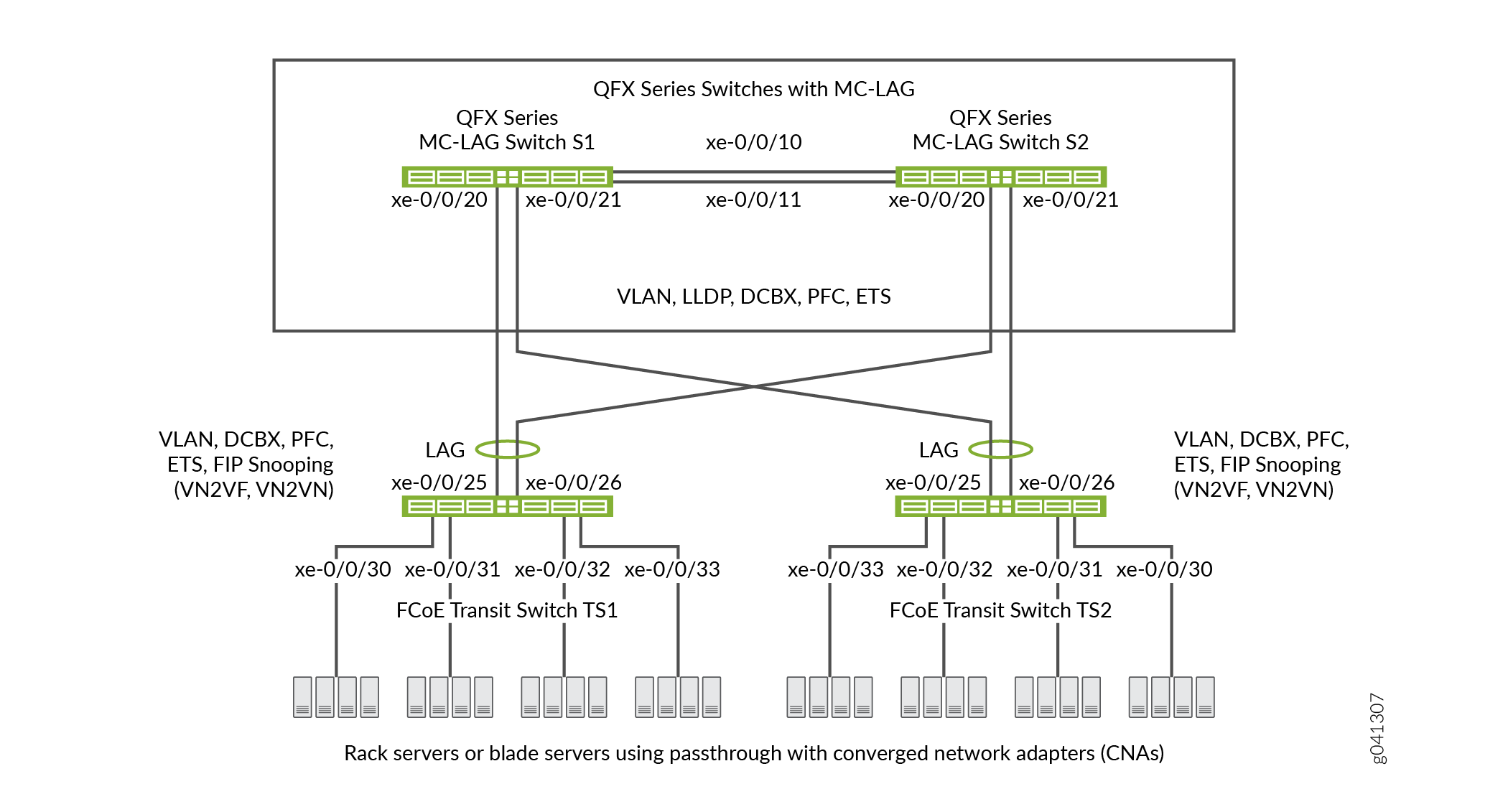 de trânsito FCoE
A Tabela 3 mostra os componentes de configuração para este exemplo.
Componente |
Configurações |
|---|---|
Hardware |
Quatro switches QFX3500 (dois para formar o MC-LAG como switches de trânsito de passagem e dois switches de trânsito para acesso FCoE). |
Classe de encaminhamento (todos os switches) |
Classe de encaminhamento padrão |
Classificador (encaminhamento de mapeamento de classe do tráfego de entrada para prioridade IEEE) |
Classificador de confiança IEEE 802.1p padrão em todas as interfaces FCoE. |
LAGs e MC-LAG |
S1 — As portas xe-0/0/10 e x-0/0/11 são membros do LAG ae0, que conecta o Switch S1 ao Switch S2.As portas xe-0/0/20 e xe-0/0/21 são membros do MC-LAG ae1.Todas as portas estão configuradas no S2 — Portas xe-0/0/10 e x-0/0/11 são membros do LAG ae0, que conecta o Switch S2 ao Switch S1.As portas xe-0/0/20 e xe-0/0/21 são membros do MC-LAG ae1.Todas as portas estão configuradas no
Nota:
As portas xe-0/0/20 e xe-0/0/21 nos switches S1 e S2 são os membros do MC-LAG. TS1 — As portas xe-0/0/25 e x-0/26 são membros do LAG ae1, configurados no TS2 — As portas xe-0/0/25 e x-0/26 são membros do LAG ae1, configurados no |
Agendador de filas FCoE (todos os switches) |
|
Encaminhamento de mapeamento de classe a agendador (todos os switches) |
Mapa do agendador |
Conjunto de aulas de encaminhamento (grupo de prioridade do FCoE, todos os switches) |
Interfaces de saída:
|
Perfil de controle de tráfego (todos os switches) |
|
Perfil de notificação de congestionamento PFC (todos os switches) |
Interfaces de entrada:
|
Nome e identificação da tag FCoE VLAN |
Nome — Inclua o FCoE VLAN nas interfaces que transportam tráfego FCoE nos quatro switches. Desativar o IGMP bisbilhotando as interfaces que pertencem ao FCoE VLAN nos quatro switches. |
Espionagem fip |
Habilite a espionagem da FIP nos switches de trânsito TS1 e TS2 no FCoE VLAN. Configure as interfaces LAG que se conectam aos switches MC-LAG como interfaces confiáveis de FCoE para que não realizem espionagem de FIP. Este exemplo permite VN2VN_Port FIP bisbilhotar as interfaces de switch de trânsito FCoE conectadas aos servidores FCoE. O exemplo é igualmente válido com VN2VF_Port espionagem FIP habilitada nas portas de acesso do switch de trânsito. O método de espionagem fip que você habilita depende da configuração da sua rede. |
Este exemplo usa o classificador BA confiável IEEE 802.1p padrão, que é aplicado automaticamente ao modo tronco e portas de modo de acesso com tags se você não aplicar um classificador explicitamente configurado.
Para configurar CoS para tráfego FCoE em um MC-LAG:
Use a classe de encaminhamento de FCoE padrão e o mapeamento de classe para fila de encaminhamento (não configure explicitamente a classe de encaminhamento ou a fila de saída do FCoE). A classe de encaminhamento de FCoE padrão é
fcoe, e a fila de saída padrão é a fila3.Nota:No Junos OS Release 12.2, o tráfego mapeado para aulas de encaminhamento explicitamente configuradas, mesmo aulas de encaminhamento sem perdas, como
fcoe, é tratado como tráfego perdido (best-effort) e não recebe tratamento sem perdas. Para receber tratamento sem perdas na Versão 12.2, o tráfego deve usar uma das aulas de encaminhamento sem perdas padrão (fcoeouno-loss).No Junos OS Release 12.3 e posterior, você pode incluir o atributo de queda de pacote sem perda na configuração explícita de classe de encaminhamento para configurar uma classe de encaminhamento sem perdas.
Use o classificador BA confiável padrão, que mapeia pacotes de entrada para as aulas de encaminhamento pelo ponto de código IEEE 802.1p (prioridade CoS) do pacote. O classificador confiável é o classificador padrão para interfaces nos modos de porta de tronco e acesso com tags. O classificador confiável padrão mapeia pacotes de entrada com o ponto de código IEEE 802.1p 3 (
011) para a classe de encaminhamento FCoE. Se você optar por configurar o classificador BA em vez de usar o classificador padrão, você deve garantir que o tráfego FCoE seja classificado em aulas de encaminhamento exatamente da mesma maneira em ambos os switches MC-LAG. O uso do classificador padrão garante uma configuração de classificador consistente nas portas MC-LAG.Configure um perfil de notificação de congestionamento que habilita o PFC no ponto de código FCoE (ponto
011de código neste exemplo). A configuração do perfil de notificação de congestionamento deve ser a mesma em ambos os switches MC-LAG.Aplique o perfil de notificação de congestionamento nas interfaces.
Configure uma seleção aprimorada de transmissão (ETS, também conhecida como agendamento hierárquico) nas interfaces para fornecer a largura de banda necessária para o transporte de FCoE sem perdas. A configuração do ETS inclui a configuração da programação de largura de banda para a classe de encaminhamento FCoE, um conjunto de classes de encaminhamento (grupo prioritário) que inclui a classe de encaminhamento de FCoE e um perfil de controle de tráfego para atribuir largura de banda ao conjunto de classe de encaminhamento que inclui tráfego FCoE.
Aplique o agendamento de ETS nas interfaces.
Configure o modo de porta, MTU e FCoE de estado confiável ou não confiável para cada interface para oferecer suporte ao transporte de FCoE sem perdas.
Além disso, este exemplo descreve como habilitar o FIP a bisbilhotar as portas TS1 e TS2 do switch de trânsito que estão conectadas aos servidores FCoE e como desativar o IGMP bisbilhotando o FCoE VLAN. Para fornecer acesso seguro, a espionagem FIP deve ser habilitada nas portas de acesso FCoE.
Este exemplo se concentra na configuração de CoS para oferecer suporte ao transporte FCoE sem perdas em um MC-LAG. Este exemplo não descreve como configurar as propriedades dos MC-LAGs e LAGs, embora mostre como configurar as características de porta necessárias para suportar o transporte sem perdas e como atribuir interfaces ao MC-LAG e aos LAGs.
Antes de configurar o CoS, configure:
Os MC-LAGs que conectam os switches S1 e S2 aos switches TS1 e TS2.
Os LAGs que conectam os switches de trânsito TS1 e TS2 aos switches MC-LAG S1 e S2.
O LAG que conecta o Switch S1 ao Switch S2.
Configuração
Para configurar o CoS para o transporte de FCoE sem perdas em um MC-LAG, execute essas tarefas:
- Configuração rápida da CLI
- Configuração dos switches MC-LAG S1 e S2
- Configuração dos switches de trânsito FCoE TS1 e TS2
- Resultados
Configuração rápida da CLI
Para configurar cos rapidamente para o transporte de FCoE sem perdas em um MC-LAG, copie os seguintes comandos, cole-os em um arquivo de texto, remova quebras de linha, altere variáveis e detalhes para combinar com a configuração da sua rede e, em seguida, copie e cole os comandos no CLI para MC-LAG Switch S1 e MC-LAG Switch S2 no [edit] nível de hierarquia. As configurações dos switches S1 e S2 são idênticas porque a configuração cos deve ser idêntica, e como este exemplo usa as mesmas portas em ambos os switches.
Switch S1 e Switch S2
set class-of-service schedulers fcoe-sched priority low transmit-rate 3g set class-of-service schedulers fcoe-sched shaping-rate percent 100 set class-of-service scheduler-maps fcoe-map forwarding-class fcoe scheduler fcoe-sched set class-of-service forwarding-class-sets fcoe-pg class fcoe set class-of-service traffic-control-profiles fcoe-tcp scheduler-map fcoe-map guaranteed-rate 3g set class-of-service traffic-control-profiles fcoe-tcp shaping-rate percent 100 set class-of-service interfaces ae0 forwarding-class-set fcoe-pg output-traffic-control-profile fcoe-tcp set class-of-service interfaces ae1 forwarding-class-set fcoe-pg output-traffic-control-profile fcoe-tcp set class-of-service congestion-notification-profile fcoe-cnp input ieee-802.1 code-point 011 pfc set class-of-service interfaces ae0 congestion-notification-profile fcoe-cnp set class-of-service interfaces ae1 congestion-notification-profile fcoe-cnp set vlans fcoe_vlan vlan-id 100 set protocols igmp-snooping vlan fcoe_vlan disable set interfaces xe-0/0/10 ether-options 802.3ad ae0 set interfaces xe-0/0/11 ether-options 802.3ad ae0 set interfaces xe-0/0/20 ether-options 802.3ad ae1 set interfaces xe-0/0/21 ether-options 802.3ad ae1 set interfaces ae0 unit 0 family ethernet-switching port-mode trunk vlan members fcoe_vlan set interfaces ae1 unit 0 family ethernet-switching port-mode trunk vlan members fcoe_vlan set interfaces ae0 mtu 2180 set interfaces ae1 mtu 2180 set ethernet-switching-options secure-access-port interface ae0 fcoe-trusted set ethernet-switching-options secure-access-port interface ae1 fcoe-trusted
Para configurar CoS rapidamente para o transporte de FCoE sem perdas em um MC-LAG, copie os seguintes comandos, cole-os em um arquivo de texto, remova quebras de linha, altere variáveis e detalhes para combinar com a configuração da sua rede e, em seguida, copie e cole os comandos no CLI para Transit Switch TS1 e Transit Switch TS2 no [edit] nível de hierarquia. As configurações dos switches TS1 e TS2 são idênticas porque a configuração cos deve ser idêntica, e como este exemplo usa as mesmas portas em ambos os switches.
Switch TS1 e Switch TS2
set class-of-service schedulers fcoe-sched priority low transmit-rate 3g set class-of-service schedulers fcoe-sched shaping-rate percent 100 set class-of-service scheduler-maps fcoe-map forwarding-class fcoe scheduler fcoe-sched set class-of-service forwarding-class-sets fcoe-pg class fcoe set class-of-service traffic-control-profiles fcoe-tcp scheduler-map fcoe-map guaranteed-rate 3g set class-of-service traffic-control-profiles fcoe-tcp shaping-rate percent 100 set class-of-service interfaces ae1 forwarding-class-set fcoe-pg output-traffic-control-profile fcoe-tcp set class-of-service interfaces xe-0/0/30 forwarding-class-set fcoe-pg output-traffic-control-profile fcoe-tcp set class-of-service interfaces xe-0/0/31 forwarding-class-set fcoe-pg output-traffic-control-profile fcoe-tcp set class-of-service interfaces xe-0/0/32 forwarding-class-set fcoe-pg output-traffic-control-profile fcoe-tcp set class-of-service interfaces xe-0/0/33 forwarding-class-set fcoe-pg output-traffic-control-profile fcoe-tcp set class-of-service congestion-notification-profile fcoe-cnp input ieee-802.1 code-point 011 pfc set class-of-service interfaces ae1 congestion-notification-profile fcoe-cnp set class-of-service interfaces xe-0/0/30 congestion-notification-profile fcoe-cnp set class-of-service interfaces xe-0/0/31 congestion-notification-profile fcoe-cnp set class-of-service interfaces xe-0/0/32 congestion-notification-profile fcoe-cnp set class-of-service interfaces xe-0/0/33 congestion-notification-profile fcoe-cnp set vlans fcoe_vlan vlan-id 100 set protocols igmp-snooping vlan fcoe_vlan disable set interfaces xe-0/0/25 ether-options 802.3ad ae1 set interfaces xe-0/0/26 ether-options 802.3ad ae1 set interfaces ae1 unit 0 family ethernet-switching port-mode trunk vlan members fcoe_vlan set interfaces xe-0/0/30 unit 0 family ethernet-switching port-mode tagged-access vlan members fcoe_vlan set interfaces xe-0/0/31 unit 0 family ethernet-switching port-mode tagged-access vlan members fcoe_vlan set interfaces xe-0/0/32 unit 0 family ethernet-switching port-mode tagged-access vlan members fcoe_vlan set interfaces xe-0/0/33 unit 0 family ethernet-switching port-mode tagged-access vlan members fcoe_vlan set interfaces ae1 mtu 2180 set interfaces xe-0/0/30 mtu 2180 set interfaces xe-0/0/31 mtu 2180 set interfaces xe-0/0/32 mtu 2180 set interfaces xe-0/0/33 mtu 2180 set ethernet-switching-options secure-access-port interface ae1 fcoe-trusted set ethernet-switching-options secure-access-port vlan fcoe_vlan examine-fip examine-vn2v2 beacon-period 90000
Configuração dos switches MC-LAG S1 e S2
Procedimento passo a passo
Para configurar o agendamento de recursos cos (ETS), PFC, o FCoE VLAN e a associação de interface LAG e MC-LAG e características para oferecer suporte ao transporte de FCoE sem perdas em um MC-LAG (este exemplo usa a classe de encaminhamento padrão fcoe e o classificador padrão para mapear o tráfego FCoE de entrada para o ponto 011de código FCoE IEEE 802.1p, para que você não os configure):
Configure o agendamento de saída para a fila de FCoE.
[edit class-of-service schedulers fcoe-sched] user@switch# set priority low transmit-rate 3g user@switch# set shaping-rate percent 100
Mapeie a classe de encaminhamento de FCoE para o agendador FCoE ().
fcoe-sched[edit class-of-service] user@switch# set scheduler-maps fcoe-map forwarding-class fcoe scheduler fcoe-sched
Configure o conjunto de classes de encaminhamento (
fcoe-pg) para o tráfego FCoE.[edit class-of-service] user@switch# set forwarding-class-sets fcoe-pg class fcoe
Defina o perfil de controle de tráfego (
fcoe-tcp) para usar no conjunto de classes de encaminhamento FCoE.[edit class-of-service traffic-control-profiles fcoe-tcp] user@switch# set scheduler-map fcoe-map guaranteed-rate 3g user@switch# set shaping-rate percent 100
Aplique o conjunto de classes de encaminhamento FCoE e o perfil de controle de tráfego para as interfaces LAG e MC-LAG.
[edit class-of-service] user@switch# set interfaces ae0 forwarding-class-set fcoe-pg output-traffic-control-profile fcoe-tcp user@switch# set interfaces ae1 forwarding-class-set fcoe-pg output-traffic-control-profile fcoe-tcp
Habilite o PFC na prioridade do FCoE criando um perfil de notificação de congestionamento (
fcoe-cnp) que aplica o FCoE ao ponto011de código IEEE 802.1.[edit class-of-service] user@switch# set congestion-notification-profile fcoe-cnp input ieee-802.1 code-point 011 pfc
Aplique a configuração do PFC nas interfaces LAG e MC-LAG.
[edit class-of-service] user@switch# set interfaces ae0 congestion-notification-profile fcoe-cnp user@switch# set interfaces ae1 congestion-notification-profile fcoe-cnp
Configure a VLAN para tráfego FCoE (
fcoe_vlan).[edit vlans] user@switch# set fcoe_vlan vlan-id 100
Desativar o IGMP bisbilhotando o FCoE VLAN.
[edit protocols] user@switch# set igmp-snooping vlan fcoe_vlan disable
Adicione as interfaces de membro ao LAG entre os dois switches MC-LAG.
[edit interfaces] user@switch# set xe-0/0/10 ether-options 802.3ad ae0 user@switch# set xe-0/0/11 ether-options 802.3ad ae0
Adicione as interfaces de membro ao MC-LAG.
[edit interfaces] user@switch# set xe-0/0/20 ether-options 802.3ad ae1 user@switch# set xe-0/0/21 ether-options 802.3ad ae1
Configure o modo de porta como
trunke a associação no FCoE VLAN (fcoe_vlan)para o LAG (ae0) e para o MC-LAG (ae1).[edit interfaces] user@switch# set ae0 unit 0 family ethernet-switching port-mode trunk vlan members fcoe_vlan user@switch# set ae1 unit 0 family ethernet-switching port-mode trunk vlan members fcoe_vlan
Configure o MTU para
2180as interfaces LAG e MC-LAG.2180 bytes é o tamanho mínimo necessário para lidar com pacotes FCoE devido aos tamanhos de carga e cabeçalho. Você pode configurar o MTU para um número maior de bytes se desejado, mas não menos do que 2180 bytes.
[edit interfaces] user@switch# set ae0 mtu 2180 user@switch# set ae1 mtu 2180
Definir as interfaces LAG e MC-LAG como portas confiáveis do FCoE.
As portas que se conectam a outros switches devem ser confiáveis e não devem realizar espionagem FIP.
[edit ethernet-switching-options secure-access-port interface] user@switch# set ae0 fcoe-trusted user@switch# set ae1 fcoe-trusted
Configuração dos switches de trânsito FCoE TS1 e TS2
Procedimento passo a passo
A configuração de CoS nos switches FCoE Transit TS1 e TS2 é semelhante à configuração cos nos switches MC-LAG S1 e S2. No entanto, as configurações de porta diferem, e você deve habilitar a espionagem FIP nas portas de acesso TS1 e Switch TS2 FCoE.
Para configurar o agendamento de recursos (ETS), PFC, o FCoE VLAN e a associação e características da interface LAG para oferecer suporte ao transporte FCoE sem perdas no MC-LAG (este exemplo usa a classe de encaminhamento padrão fcoe e o classificador padrão para mapear o tráfego FCoE de entrada no ponto 011de código FCoE IEEE 802.1p, para que você não os configure):
Configure o agendamento de saída para a fila de FCoE.
[edit class-of-service schedulers fcoe-sched] user@switch# set priority low transmit-rate 3g user@switch# set shaping-rate percent 100
Mapeie a classe de encaminhamento de FCoE para o agendador FCoE ().
fcoe-sched[edit class-of-service] user@switch# set scheduler-maps fcoe-map forwarding-class fcoe scheduler fcoe-sched
Configure o conjunto de classes de encaminhamento (
fcoe-pg) para o tráfego FCoE.[edit class-of-service] user@switch# set forwarding-class-sets fcoe-pg class fcoe
Defina o perfil de controle de tráfego (
fcoe-tcp) para usar no conjunto de classes de encaminhamento FCoE.[edit class-of-service] user@switch# set traffic-control-profiles fcoe-tcp scheduler-map fcoe-map guaranteed-rate 3g user@switch# set traffic-control-profiles fcoe-tcp shaping-rate percent 100
Aplique o conjunto de classes de encaminhamento FCoE e o perfil de controle de tráfego para a interface LAG e para as interfaces de acesso FCoE.
[edit class-of-service] user@switch# set interfaces ae1 forwarding-class-set fcoe-pg output-traffic-control-profile fcoe-tcp user@switch# set interfaces xe-0/0/30 forwarding-class-set fcoe-pg output-traffic-control-profile fcoe-tcp user@switch# set interfaces xe-0/0/31 forwarding-class-set fcoe-pg output-traffic-control-profile fcoe-tcp user@switch# set interfaces xe-0/0/32 forwarding-class-set fcoe-pg output-traffic-control-profile fcoe-tcp user@switch# set interfaces xe-0/0/33 forwarding-class-set fcoe-pg output-traffic-control-profile fcoe-tcp
Habilite o PFC na prioridade do FCoE criando um perfil de notificação de congestionamento (
fcoe-cnp) que aplica o FCoE ao ponto011de código IEEE 802.1.[edit class-of-service] user@switch# set congestion-notification-profile fcoe-cnp input ieee-802.1 code-point 011 pfc
Aplique a configuração do PFC na interface LAG e nas interfaces de acesso FCoE.
[edit class-of-service] user@switch# set interfaces ae1 congestion-notification-profile fcoe-cnp user@switch# set interfaces xe-0/0/30 congestion-notification-profile fcoe-cnp user@switch# set interfaces xe-0/0/31 congestion-notification-profile fcoe-cnp user@switch# set interfaces xe-0/0/32 congestion-notification-profile fcoe-cnp user@switch# set interfaces xe-0/0/33 congestion-notification-profile fcoe-cnp
Configure a VLAN para tráfego FCoE (
fcoe_vlan).[edit vlans] user@switch# set fcoe_vlan vlan-id 100
Desativar o IGMP bisbilhotando o FCoE VLAN.
[edit protocols] user@switch# set igmp-snooping vlan fcoe_vlan disable
Adicione as interfaces de membro ao LAG.
[edit interfaces] user@switch# set xe-0/0/25 ether-options 802.3ad ae1 user@switch# set xe-0/0/26 ether-options 802.3ad ae1
No LAG (
ae1), configure o modo de porta comotrunke a adesão ao FCoE VLAN (fcoe_vlan).[edit interfaces] user@switch# set ae1 unit 0 family ethernet-switching port-mode trunk vlan members fcoe_vlan
Nas interfaces de acesso FCoE (
xe-0/0/30,xe-0/0/31, ,xe-0/0/32, ),xe-0/0/33configure o modo de porta comotagged-accesse a associação no FCoE VLAN (fcoe_vlan).[edit interfaces] user@switch# set xe-0/0/30 unit 0 family ethernet-switching port-mode tagged-access vlan members fcoe_vlan user@switch# set xe-0/0/31 unit 0 family ethernet-switching port-mode tagged-access vlan members fcoe_vlan user@switch# set xe-0/0/32 unit 0 family ethernet-switching port-mode tagged-access vlan members fcoe_vlan user@switch# set xe-0/0/33 unit 0 family ethernet-switching port-mode tagged-access vlan members fcoe_vlan
Configure o MTU para
2180as interfaces de acesso LAG e FCoE.2180 bytes é o tamanho mínimo necessário para lidar com pacotes FCoE devido aos tamanhos de carga e cabeçalho; você pode configurar o MTU para um número maior de bytes se desejado, mas não menos do que 2180 bytes.
[edit interfaces] user@switch# set ae1 mtu 2180 user@switch# set xe-0/0/30 mtu 2180 user@switch# set xe-0/0/31 mtu 2180 user@switch# set xe-0/0/32 mtu 2180 user@switch# set xe-0/0/33 mtu 2180
Definir a interface LAG como uma porta confiável para FCoE. As portas que se conectam a outros switches devem ser confiáveis e não devem realizar espionagem fip:
[edit ethernet-switching-options] user@switch# set secure-access-port interface ae1 fcoe-trusted
Nota:As portas de acesso xe-0/0/30, xe-0/0/31, xe-0/32 e xe-0/33 não estão configuradas como portas confiáveis para FCoE. As portas de acesso permanecem no estado padrão como portas não confiáveis porque elas se conectam diretamente aos dispositivos FCoE e devem realizar espionagem fip para garantir a segurança da rede.
Habilite a espionagem da FIP no FCoE VLAN para evitar o acesso à rede FCoE não autorizado (este exemplo usa VN2VN_Port espionagem fip; o exemplo é igualmente válido se você usar VN2VF_Port espionagem fip).
[edit ethernet-switching-options] user@switch# set secure-access-port vlan fcoe_vlan examine-fip examine-vn2vn beacon-period 90000
Resultados
Exibir os resultados da configuração cos no MC-LAG Switch S1 e no MC-LAG Switch S2 (os resultados em ambos os switches são os mesmos).
user@switch> show configuration class-of-service
traffic-control-profiles {
fcoe-tcp {
scheduler-map fcoe-map;
shaping-rate percent 100;
guaranteed-rate 3g;
}
}
forwarding-class-sets {
fcoe-pg {
class fcoe;
}
}
congestion-notification-profile {
fcoe-cnp {
input {
ieee-802.1 {
code-point 011 {
pfc;
}
}
}
}
}
interfaces {
ae0 {
forwarding-class-set {
fcoe-pg {
output-traffic-control-profile fcoe-tcp;
}
}
congestion-notification-profile fcoe-cnp;
}
ae1 {
forwarding-class-set {
fcoe-pg {
output-traffic-control-profile fcoe-tcp;
}
}
congestion-notification-profile fcoe-cnp;
}
}
scheduler-maps {
fcoe-map {
forwarding-class fcoe scheduler fcoe-sched;
}
}
schedulers {
fcoe-sched {
transmit-rate 3g;
shaping-rate percent 100;
priority low;
}
}
A classe de encaminhamento e as configurações do classificador não são mostradas porque o show comando não exibe partes padrão da configuração.
Exibir os resultados da configuração de CoS no FCoE Transit Switch TS1 e no FCoE Transit Switch TS2 (os resultados em ambos os switches de trânsito são os mesmos).
user@switch> show configuration class-of-service
traffic-control-profiles {
fcoe-tcp {
scheduler-map fcoe-map;
shaping-rate percent 100;
guaranteed-rate 3g;
}
}
forwarding-class-sets {
fcoe-pg {
class fcoe;
}
}
congestion-notification-profile {
fcoe-cnp {
input {
ieee-802.1 {
code-point 011 {
pfc;
}
}
}
}
}
interfaces {
xe-0/0/30 {
forwarding-class-set {
fcoe-pg {
output-traffic-control-profile fcoe-tcp;
}
}
congestion-notification-profile fcoe-cnp;
}
xe-0/0/31 {
forwarding-class-set {
fcoe-pg {
output-traffic-control-profile fcoe-tcp;
}
}
congestion-notification-profile fcoe-cnp;
}
xe-0/0/32 {
forwarding-class-set {
fcoe-pg {
output-traffic-control-profile fcoe-tcp;
}
}
congestion-notification-profile fcoe-cnp;
}
xe-0/0/33 {
forwarding-class-set {
fcoe-pg {
output-traffic-control-profile fcoe-tcp;
}
}
congestion-notification-profile fcoe-cnp;
}
ae1 {
forwarding-class-set {
fcoe-pg {
output-traffic-control-profile fcoe-tcp;
}
}
congestion-notification-profile fcoe-cnp;
}
}
scheduler-maps {
fcoe-map {
forwarding-class fcoe scheduler fcoe-sched;
}
}
schedulers {
fcoe-sched {
transmit-rate 3g;
shaping-rate percent 100;
priority low;
}
}
Verificação
Para verificar se os componentes cos e a espionagem FIP foram configurados e estão operando corretamente, execute essas tarefas. Como este exemplo usa a classe de encaminhamento padrão fcoe e o classificador de confiança IEEE 802.1p padrão, a verificação dessas configurações não é mostrada.
- Verificando se os agendadores de fila de saída foram criados
- Verificando se o agendador de saída de grupo prioritário (perfil de controle de tráfego) foi criado
- Verificando se o conjunto de classes de encaminhamento (Grupo prioritário) foi criado
- Verificar se o controle de fluxo baseado em prioridade foi habilitado
- Verificando se a classe de interface de configuração de serviços foi criada
- Verificando se as interfaces estão configuradas corretamente
- Verificando se a snooping fip está habilitada no FCoE VLAN nos switches de trânsito FCoE Interfaces de acesso TS1 e TS2
- Verificando se o modo snooping FIP está correto nos switches de trânsito FCoE TS1 e TS2
- Verificando se a snooping do IGMP está desabilitada no FCoE VLAN
Verificando se os agendadores de fila de saída foram criados
Propósito
Verifique se o agendador de fila de saída para tráfego FCoE tem os parâmetros e prioridades de largura de banda corretos, e é mapeado para a classe de encaminhamento correta (fila de saída). A verificação do agendador de filas é a mesma em cada um dos quatro switches.
Ação
Liste o mapa do agendador usando o comando show class-of-service scheduler-map fcoe-mapde modo operacional:
user@switch> show class-of-service scheduler-map fcoe-map
Scheduler map: fcoe-map, Index: 9023
Scheduler: fcoe-sched, Forwarding class: fcoe, Index: 37289
Transmit rate: 3000000000 bps, Rate Limit: none, Buffer size: remainder,
Buffer Limit: none, Priority: low
Excess Priority: unspecified
Shaping rate: 100 percent,
drop-profile-map-set-type: mark
Drop profiles:
Loss priority Protocol Index Name
Low any 1 <default-drop-profile>
Medium high any 1 <default-drop-profile>
High any 1 <default-drop-profile>
Significado
O show class-of-service scheduler-map fcoe-map comando lista as propriedades do mapa fcoe-mapdo agendador. A saída de comando inclui:
O nome do mapa do agendador (
fcoe-map)O nome do agendador (
fcoe-sched)As aulas de encaminhamento mapeadas para o agendador (
fcoe)A largura de banda de fila mínima garantida (taxa de
3000000000 bpstransmissão)A prioridade de agendamento (
low)A largura de banda máxima no grupo de prioridade que a fila pode consumir (taxa
100 percentde modelagem)A prioridade de perda de perfil de queda para cada nome de perfil de queda. Este exemplo não inclui perfis de queda porque você não aplica perfis de queda ao tráfego FCoE.
Verificando se o agendador de saída de grupo prioritário (perfil de controle de tráfego) foi criado
Propósito
Verifique se o perfil de fcoe-tcp controle de tráfego foi criado com os parâmetros de largura de banda e mapeamento de agendamento corretos. A verificação do agendador de grupos prioritários é a mesma em cada um dos quatro switches.
Ação
Liste as propriedades do perfil de controle de tráfego FCoE usando o comando show class-of-service traffic-control-profile fcoe-tcpdo modo operacional:
user@switch> show class-of-service traffic-control-profile fcoe-tcp Traffic control profile: fcoe-tcp, Index: 18303 Shaping rate: 100 percent Scheduler map: fcoe-map Guaranteed rate: 3000000000
Significado
O show class-of-service traffic-control-profile fcoe-tcp comando lista todos os perfis de controle de tráfego configurados. Para cada perfil de controle de tráfego, a saída de comando inclui:
O nome do perfil de controle de tráfego (
fcoe-tcp)A largura de banda de porta máxima que o grupo prioritário pode consumir (taxa
100 percentde modelagem)O mapa do agendador associado ao perfil de controle de tráfego (
fcoe-map)Largura de banda de porta de grupo de prioridade garantida mínima (taxa
3000000000garantida em bps)
Verificando se o conjunto de classes de encaminhamento (Grupo prioritário) foi criado
Propósito
Verifique se o grupo prioritário do FCoE foi criado e se a fcoe prioridade (classe de encaminhamento) pertence ao grupo prioritário do FCoE. A verificação do conjunto de classe de encaminhamento é a mesma em cada um dos quatro switches.
Ação
Liste os conjuntos de classe de encaminhamento usando o comando show class-of-service forwarding-class-set fcoe-pgdo modo operacional:
user@switch> show class-of-service forwarding-class-set fcoe-pg Forwarding class set: fcoe-pg, Type: normal-type, Forwarding class set index: 31420 Forwarding class Index fcoe 1
Significado
O show class-of-service forwarding-class-set fcoe-pg comando lista todas as classes de encaminhamento (prioridades) que pertencem ao fcoe-pg grupo prioritário e o número de índice interno do grupo prioritário. A saída de comando mostra que o conjunto fcoe-pg de classes de encaminhamento inclui a classe fcoede encaminhamento.
Verificar se o controle de fluxo baseado em prioridade foi habilitado
Propósito
Verifique se o PFC está habilitado no ponto de código FCoE. A verificação de PFC é a mesma em cada um dos quatro switches.
Ação
Liste o perfil de notificação de congestionamento FCoE usando o comando show class-of-service congestion-notification fcoe-cnpdo modo operacional:
user@switch> show class-of-service congestion-notification fcoe-cnp
Type: Input, Name: fcoe-cnp, Index: 6879
Cable Length: 100 m
Priority PFC MRU
000 Disabled
001 Disabled
010 Disabled
011 Enabled 2500
100 Disabled
101 Disabled
110 Disabled
111 Disabled
Type: Output
Priority Flow-Control-Queues
000
0
001
1
010
2
011
3
100
4
101
5
110
6
111
7
Significado
O show class-of-service congestion-notification fcoe-cnp comando lista todos os pontos de código IEEE 802.1p no perfil de notificação de congestionamento habilitado para PFC. A saída de comando mostra que o PFC está habilitado em ponto 011 de código (fcoe fila) para o perfil de fcoe-cnp notificação de congestionamento.
O comando também mostra o comprimento padrão do cabo (100 metros), a unidade de recebimento máximo padrão (2500 bytes) e o mapeamento padrão de prioridades para filas de saída porque este exemplo não inclui configurar essas opções.
Verificando se a classe de interface de configuração de serviços foi criada
Propósito
Verifique se as propriedades cos das interfaces estão corretas. A saída de verificação nos switches MC-LAG S1 e S2 difere da saída dos switches de trânsito FCoE TS1 e TS2.
Ação
Liste a configuração CoS da interface nos switches MC-LAG S1 e S2 usando o comando show configuration class-of-service interfacesdo modo operacional:
user@switch> show configuration class-of-service interfaces
ae0 {
forwarding-class-set {
fcoe-pg {
output-traffic-control-profile fcoe-tcp;
}
}
congestion-notification-profile fcoe-cnp;
}
ae1 {
forwarding-class-set {
fcoe-pg {
output-traffic-control-profile fcoe-tcp;
}
}
congestion-notification-profile fcoe-cnp;
}
Liste a configuração CoS da interface nos switches FCoE Transit TS1 e TS2 usando o comando show configuration class-of-service interfacesdo modo operacional:
user@switch> show configuration class-of-service interfaces
xe-0/0/30 {
forwarding-class-set {
fcoe-pg {
output-traffic-control-profile fcoe-tcp;
}
}
congestion-notification-profile fcoe-cnp;
}
xe-0/0/31 {
forwarding-class-set {
fcoe-pg {
output-traffic-control-profile fcoe-tcp;
}
}
congestion-notification-profile fcoe-cnp;
}
xe-0/0/32 {
forwarding-class-set {
fcoe-pg {
output-traffic-control-profile fcoe-tcp;
}
}
congestion-notification-profile fcoe-cnp;
}
xe-0/0/33 {
forwarding-class-set {
fcoe-pg {
output-traffic-control-profile fcoe-tcp;
}
}
congestion-notification-profile fcoe-cnp;
}
ae1 {
forwarding-class-set {
fcoe-pg {
output-traffic-control-profile fcoe-tcp;
}
}
congestion-notification-profile fcoe-cnp;
}
Significado
O show configuration class-of-service interfaces comando lista a classe de configuração de serviço para todas as interfaces. Para cada interface, a saída de comando inclui:
O nome da interface (por exemplo,
ae0ouxe-0/0/30)O nome do conjunto de classe de encaminhamento associado à interface (
fcoe-pg)O nome do perfil de controle de tráfego associado à interface (perfil de controle de tráfego de saída)
fcoe-tcpO nome do perfil de notificação de congestionamento associado à interface (
fcoe-cnp)
Interfaces que são membros de um LAG não são mostradas individualmente. A configuração DE LAG ou MC-LAG CoS é aplicada a todas as interfaces que são membros do LAG ou MC-LAG. Por exemplo, a saída de configuração CoS da interface nos switches MC-LAG S1 e S2 mostra a configuração de COS LAG, mas não mostra a configuração cos das interfaces de membro separadamente. A saída de configuração CoS da interface nos switches FCoE Transit TS1 e TS2 mostra a configuração de COS LAG, mas também mostra a configuração para interfaces xe-0/0/30, xe-0/0/31, xe-0/32 e xe-0/33, que não são membros de um LAG.
Verificando se as interfaces estão configuradas corretamente
Propósito
Verifique se a associação de LAG, MTU, associação ao VLAN e o modo de porta das interfaces estão corretos. A saída de verificação nos switches MC-LAG S1 e S2 difere da saída dos switches de trânsito FCoE TS1 e TS2.
Ação
Liste a configuração da interface nos switches MC-LAG S1 e S2 usando o comando show configuration interfacesdo modo operacional:
user@switch> show configuration interfaces
xe-0/0/10 {
ether-options {
802.3ad ae0;
}
}
xe-0/0/11 {
ether-options {
802.3ad ae0;
}
}
xe-0/0/20 {
ether-options {
802.3ad ae1;
}
}
xe-0/0/21 {
ether-options {
802.3ad ae1;
}
}
ae0 {
mtu 2180;
unit 0 {
family ethernet-switching {
port-mode trunk;
vlan {
members fcoe_vlan;
}
}
}
}
ae1 {
mtu 2180;
unit 0 {
family ethernet-switching {
port-mode trunk;
vlan {
members fcoe_vlan;
}
}
}
}
Liste a configuração da interface nos switches FCoE Transit TS1 e TS2 usando o comando show configuration interfacesdo modo operacional:
user@switch> show configuration interfaces
xe-0/0/25 {
ether-options {
802.3ad ae1;
}
}
xe-0/0/26 {
ether-options {
802.3ad ae1;
}
}
xe-0/0/30 {
mtu 2180;
unit 0 {
family ethernet-switching {
port-mode tagged-access;
vlan {
members fcoe_vlan;
}
}
}
}
xe-0/0/31 {
mtu 2180;
unit 0 {
family ethernet-switching {
port-mode tagged-access;
vlan {
members fcoe_vlan;
}
}
}
}
xe-0/0/32 {
mtu 2180;
unit 0 {
family ethernet-switching {
port-mode tagged-access;
vlan {
members fcoe_vlan;
}
}
}
}
xe-0/0/33 {
mtu 2180;
unit 0 {
family ethernet-switching {
port-mode tagged-access;
vlan {
members fcoe_vlan;
}
}
}
}
ae1 {
mtu 2180;
unit 0 {
family ethernet-switching {
port-mode trunk;
vlan {
members fcoe_vlan;
}
}
}
}
Significado
O show configuration interfaces comando lista a configuração de cada interface por nome de interface.
Para cada interface que é um membro de um LAG, o comando lista apenas o nome do LAG ao qual a interface pertence.
Para cada interface LAG e para cada interface que não é um membro de um LAG, a saída de comando inclui:
A MTU (
2180)O número da unidade da interface (
0)O modo de porta (
trunkmodo para interfaces que conectam dois switches,tagged-accessmodo para interfaces que se conectam a hosts FCoE)O nome da VLAN em que a interface é um membro (
fcoe_vlan)
Verificando se a snooping fip está habilitada no FCoE VLAN nos switches de trânsito FCoE Interfaces de acesso TS1 e TS2
Propósito
Verifique se a espionagem fip está habilitada nas interfaces de acesso FCoE VLAN. A espionagem fip é habilitada apenas nas interfaces de acesso FCoE, por isso é habilitada apenas nos switches de trânsito FCoE TS1 e TS2. A espionagem fip não está habilitada nos switches MC-LAG S1 e S2 porque a espionagem fip é feita nas portas de acesso TS1 e TS2 FCoE do switch de trânsito.
Ação
Liste a configuração de segurança de porta nos switches FCoE Transit TS1 e TS2 usando o comando show configuration ethernet-switching-options secure-access-portdo modo operacional:
user@switch> show configuration ethernet-switching-options secure-access-port
interface ae1.0 {
fcoe-trusted;
}
vlan fcoe_vlan {
examine-fip {
examine-vn2vn {
beacon-period 90000;
}
}
}
Significado
O show configuration ethernet-switching-options secure-access-port comando lista informações de segurança de porta, incluindo se uma porta é confiável. A saída de comando mostra que:
A porta
ae1.0LAG , que conecta o switch de trânsito FCoE aos switches MC-LAG, é configurada como uma interface confiável para FCoE. A espionagem FIP não é realizada nas interfaces de membro do LAG (xe-0/0/25 e xe-0/0/26).A espionagem fip está habilitada (
examine-fip) no FCoE VLAN (fcoe_vlan), o tipo de espionagem fip é VN2VN_Port espionagem fip (examine-vn2vn), e o período de beacon é definido para90000milissegundos. Nos switches de trânsito TS1 e TS2, todos os membros de interface do FCoE VLAN executam a espionagem FIP a menos que a interface seja configurada como confiável para FCoE. Nos switches de trânsito TS1 e TS2, interfaces xe-0/0/30, xe-0/0/31, xe-0/32 e xe-0/33 executam espionagem FIP porque não estão configuradas como de confiança do FCoE. Os membros de interface do LAG ae1 (xe-0/0/25 e xe-0/26) não executam espionagem FIP porque o LAG é configurado como confiável para FCoE.
Verificando se o modo snooping FIP está correto nos switches de trânsito FCoE TS1 e TS2
Propósito
Verifique se o modo de espionagem FIP está correto no FCoE VLAN. A espionagem fip é habilitada apenas nas interfaces de acesso FCoE, por isso é habilitada apenas nos switches de trânsito FCoE TS1 e TS2. A espionagem fip não está habilitada nos switches MC-LAG S1 e S2 porque a espionagem fip é feita nas portas de acesso TS1 e TS2 FCoE do switch de trânsito.
Ação
Liste a configuração de espionagem FIP nos switches FCoE Transit TS1 e TS2 usando o comando show fip snooping briefdo modo operacional:
user@switch> show fip snooping brief VLAN: fcoe_vlan, Mode: VN2VN Snooping FC-MAP: 0e:fd:00 …
A saída foi truncada para mostrar apenas as informações relevantes.
Significado
O show fip snooping brief comando lista informações de espionagem fip, incluindo o FIP snooping VLAN e o modo de espionagem FIP. A saída de comando mostra que:
A VLAN na qual a espionagem FIP está habilitada é
fcoe_vlanO modo de espionagem FIP é VN2VN_Port espionagem FIP (
VN2VN Snooping)
Verificando se a snooping do IGMP está desabilitada no FCoE VLAN
Propósito
Verifique se a espionagem de IGMP está desabilitada na VLAN FCoE nos quatro switches.
Ação
Liste as informações de protocolo de espionagem do IGMP em cada um dos quatro switches usando o show configuration protocols igmp-snooping comando:
user@switch> show configuration protocols igmp-snooping
vlan fcoe_vlan {
disable;
}
Significado
O show configuration protocols igmp-snooping comando lista a configuração de espionagem IGMP para as VLANs configuradas no switch. A saída de comando mostra que a espionagem de IGMP está desabilitada no FCoE VLAN ().fcoe_vlan
Exemplo: Intertrabalho entre EVPN-MPLS e topologia MC-LAG
Este exemplo mostra como usar a VPN Ethernet (EVPN) para estender uma rede de agregação de enlaces multichassis (MC-LAG) em uma rede MPLS para uma rede de data center ou rede de campus geograficamente distribuída.
O intertrabalho EVPN-MPLS é suportado com uma topologia MC-LAG na qual dois roteadores da Série MX, dois switches EX9200 ou uma mistura dos dois dispositivos da Juniper Networks funcionam como pares MC-LAG, que usam o Protocolo de Controle Inter-Chassis (ICCP) e um link de interchasse (ICL) para conectar e manter a topologia. Os pares MC-LAG estão conectados a um dispositivo de borda (PE) de provedor em uma rede MPLS. O dispositivo PE pode ser um roteador da Série MX ou um switch EX9200.
Este exemplo mostra como configurar os pares MC-LAG e o dispositivo PE na rede MPLS para intertrabalho entre si.
Requisitos
Este exemplo usa os seguintes componentes de hardware e software:
Três switches EX9200:
PE1 e PE2, que ambos funcionam como pares MC-LAG na topologia MC-LAG e pares EVPN BGP na rede overlay EVPN-MPLS.
PE3, que funciona como um peer BGP EVPN na rede de overlay EVPN-MPLS.
Os switches EX9200 estão executando o software Junos OS Release 17.4R1 ou posterior.
Embora a topologia MC-LAG inclua dois dispositivos de borda do cliente (CE), este exemplo se concentra na configuração do PE1, PE2 e PE3.
Visão geral e topologia
A Figura 7 mostra uma topologia MC-LAG com dispositivos de borda de provedores PE1 e PE2 que são configurados como pares MC-LAG. Os pares MC-LAG trocam informações de controle por um link ICCP e tráfego de dados por uma ICL. Neste exemplo, a ICL é uma interface Ethernet agregada que é composta por duas interfaces.
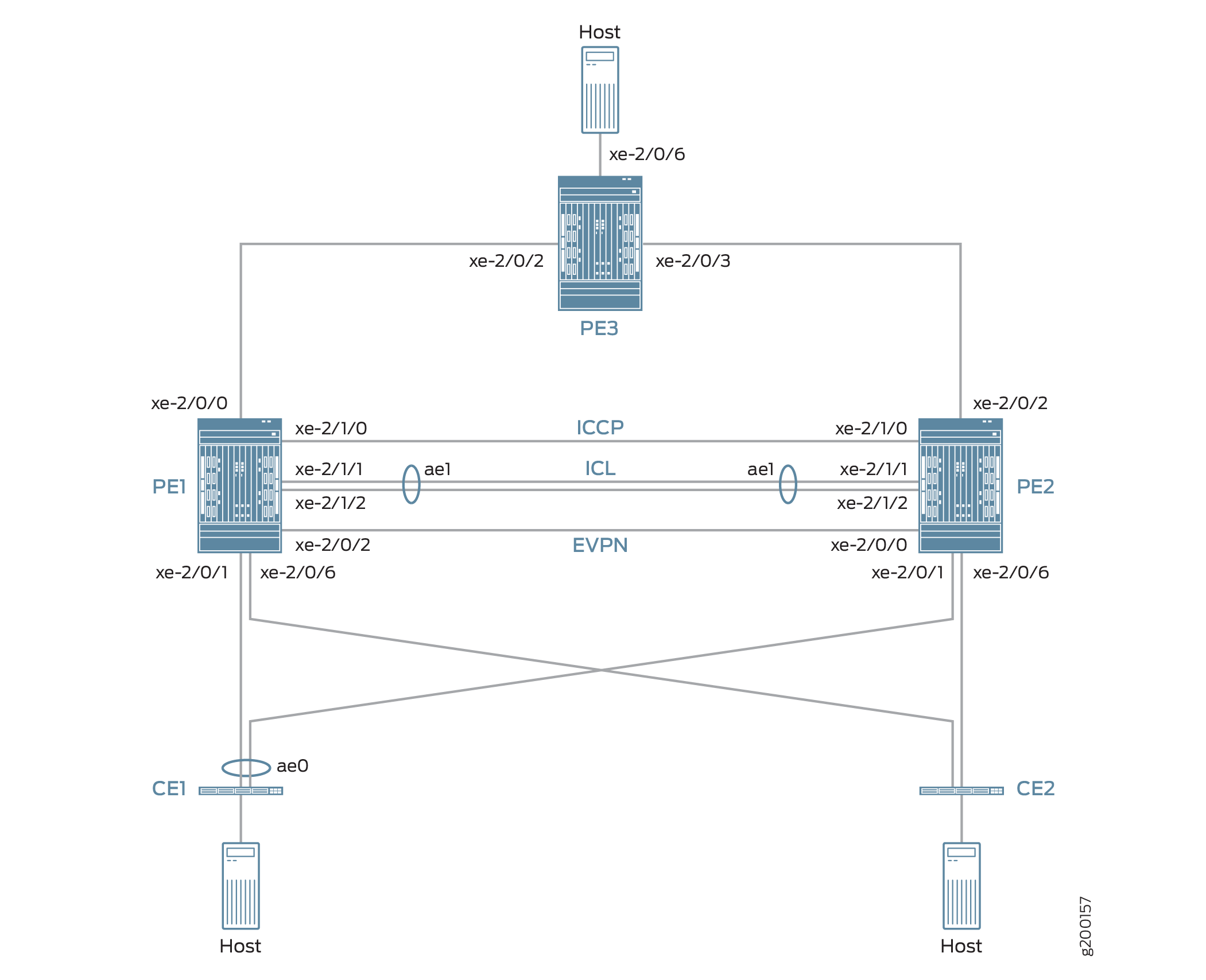 MC-LAG
A topologia da Figura 7 também inclui dispositivos CE1 e CE2, ambos multihomed para cada dispositivo PE. Os links entre o CE1 e os dois dispositivos PE são empacotados como uma interface Ethernet agregada na qual o MC-LAG no modo ativo-ativo está configurado.
A topologia da Figura 7 também inclui PE3 na borda de uma rede MPLS. O PE3 funciona como o gateway entre a rede MC-LAG e um data center ou uma rede de campus geograficamente distribuída. PE1, PE2 e PE3 executam EVPN, que permite que os hosts da rede MC-LAG se comuniquem com hosts no data center ou em outra rede de campus por meio de uma rede MPLS intervindo.
Do ponto de vista do recurso de intertrabalho EVPN-MPLS, o PE3 funciona apenas como um peer BGP EVPN, e PE1 e PE2 na topologia MC-LAG têm duas funções:
O MC-LAG está na rede MC-LAG.
O BGP da EVPN está em pares na rede EVPN-MPLS.
Devido às funções duplas, PE1 e PE2 estão configurados com atributos MC-LAG, EVPN, BGP e MPLS.
A Tabela 4 descreve os principais atributos MC-LAG e EVPN (BGP e MPLS) configurados em PE1, PE2 e PE3.
Principais atributos |
PE1 |
PE2 |
PE3 |
|---|---|---|---|
MC-LAG Attributes |
|||
Interfaces |
ICL: interface Ethernet agregada ae1, que é composta por xe-2/1/1 e xe-2/1/2 ICCP: xe-2/1/0 |
ICL: interface Ethernet agregada ae1, que é composta por xe-2/1/1 e xe-2/1/2 ICCP: xe-2/1/0 |
Não aplicável |
EVPN-MPLS |
|||
Interfaces |
Conexão ao PE3: xe-2/0/0 Conexão ao PE2: xe-2/0/2 |
Conexão ao PE3: xe-2/0/2 Conexão ao PE1: xe-2/0/0 |
Conexão ao PE1: xe-2/0/2 Conexão ao PE2: xe-2/0/3 |
Endereços IP |
Endereço peer BGP: 198.51.100.1 |
Endereço peer BGP: 198.51.100.2 |
Endereço peer BGP: 198.51.100.3 |
Sistema autônomo |
65000 |
65000 |
65000 |
Instâncias de roteamento de switches virtuais |
evpn1, evpn2, evpn3 |
evpn1, evpn2, evpn3 |
evpn1, evpn2, evpn3 |
Observe o seguinte sobre o recurso de intertrabalho EVPN-MPLS e sua configuração:
Você deve configurar os identificadores de segmentos de Ethernet (ESIs) nas interfaces de casa dupla na topologia MC-LAG. As ESIs permitem que a EVPN identifique as interfaces de casa dupla.
O único tipo de instância de roteamento que é suportada é a instância do switch virtual (
set routing-instances name instance-type virtual-switch).Nos pares MC-LAG, você deve incluir a
bgp-peerdeclaração de configuração no nível de[edit routing-instances name protocols evpn mclag]hierarquia. Essa declaração de configuração permite o intertrabalho do EVPN-MPLS com MC-LAG nos pares MC-LAG.A supressão do Protocolo de Resolução de Endereços (ARP) não é suportada.
Configuração de PE1 e PE2
Para configurar PE1 e PE2, execute essas tarefas:
- Configuração rápida da CLI
- PE1: Configuração do MC-LAG
- PE1: Configuração de EVPN-MPLS
- PE2: Configuração do MC-LAG
- PE2: Configuração de EVPN-MPLS
Configuração rápida da CLI
PE1: Configuração do MC-LAG
set chassis aggregated-devices ethernet device-count 3 set interfaces xe-2/0/1 gigether-options 802.3ad ae0 set interfaces ae0 flexible-vlan-tagging set interfaces ae0 encapsulation flexible-ethernet-services set interfaces ae0 aggregated-ether-options lacp active set interfaces ae0 aggregated-ether-options lacp periodic fast set interfaces ae0 aggregated-ether-options lacp system-id 00:00:11:11:11:11 set interfaces ae0 aggregated-ether-options lacp admin-key 1 set interfaces ae0 aggregated-ether-options mc-ae mc-ae-id 1 set interfaces ae0 aggregated-ether-options mc-ae redundancy-group 2 set interfaces ae0 aggregated-ether-options mc-ae chassis-id 0 set interfaces ae0 aggregated-ether-options mc-ae mode active-active set interfaces ae0 aggregated-ether-options mc-ae status-control active set interfaces ae0 unit 1 esi 00:11:22:33:44:55:66:77:88:99 set interfaces ae0 unit 1 esi all-active set interfaces ae0 unit 1 family ethernet-switching interface-mode trunk set interfaces ae0 unit 1 family ethernet-switching vlan members 1 set interfaces ae0 unit 2 esi 00:11:11:11:11:11:11:11:11:11 set interfaces ae0 unit 2 esi all-active set interfaces ae0 unit 2 family ethernet-switching interface-mode trunk set interfaces ae0 unit 2 family ethernet-switching vlan members 2 set interfaces ae0 unit 3 esi 00:11:22:22:22:22:22:22:22:22 set interfaces ae0 unit 3 esi all-active set interfaces ae0 unit 3 family ethernet-switching interface-mode trunk set interfaces ae0 unit 3 family ethernet-switching vlan members 3 set interfaces xe-2/0/6 enable set interfaces xe-2/0/6 flexible-vlan-tagging set interfaces xe-2/0/6 encapsulation flexible-ethernet-services set interfaces xe-2/0/6 unit 1 family ethernet-switching interface-mode trunk set interfaces xe-2/0/6 unit 1 family ethernet-switching vlan members 1 set interfaces xe-2/0/6 unit 2 family ethernet-switching interface-mode trunk set interfaces xe-2/0/6 unit 2 family ethernet-switching vlan members 2 set interfaces xe-2/0/6 unit 3 family ethernet-switching interface-mode trunk set interfaces xe-2/0/6 unit 3 family ethernet-switching vlan members 3 set interfaces xe-2/1/0 unit 0 family inet address 203.0.113.1/24 set interfaces xe-2/1/1 gigether-options 802.3ad ae1 set interfaces xe-2/1/2 gigether-options 802.3ad ae1 set interfaces ae1 flexible-vlan-tagging set interfaces ae1 encapsulation flexible-ethernet-services set interfaces ae1 aggregated-ether-options lacp active set interfaces ae1 unit 1 family ethernet-switching interface-mode trunk set interfaces ae1 unit 1 family ethernet-switching vlan members 1 set interfaces ae1 unit 2 family ethernet-switching interface-mode trunk set interfaces ae1 unit 2 family ethernet-switching vlan members 2 set interfaces ae1 unit 3 family ethernet-switching interface-mode trunk set interfaces ae1 unit 3 family ethernet-switching vlan members 3 set multi-chassis multi-chassis-protection 203.0.113.2 interface ae1 set protocols iccp local-ip-addr 203.0.113.1 set protocols iccp peer 203.0.113.2 session-establishment-hold-time 600 set protocols iccp peer 203.0.113.2 redundancy-group-id-list 2 set protocols iccp peer 203.0.113.2 liveness-detection minimum-interval 10000 set protocols iccp peer 203.0.113.2 liveness-detection multiplier 3
PE1: Configuração de EVPN-MPLS
set interfaces lo0 unit 0 family inet address 198.51.100.1/32 primary set interfaces xe-2/0/0 unit 0 family inet address 192.0.2.2/24 set interfaces xe-2/0/0 unit 0 family mpls set interfaces xe-2/0/2 unit 0 family inet address 192.0.2.111/24 set interfaces xe-2/0/2 unit 0 family mpls set interfaces irb unit 1 family inet address 10.2.1.1/24 virtual-gateway-address 10.2.1.254 set interfaces irb unit 2 family inet address 10.2.2.1/24 virtual-gateway-address 10.2.2.254 set interfaces irb unit 3 family inet address 10.2.3.1/24 virtual-gateway-address 10.2.3.254 set routing-options router-id 198.51.100.1 set routing-options autonomous-system 65000 set routing-options forwarding-table export evpn-pplb set protocols mpls interface xe-2/0/0.0 set protocols mpls interface xe-2/0/2.0 set protocols bgp group evpn type internal set protocols bgp group evpn local-address 198.51.100.1 set protocols bgp group evpn family evpn signaling set protocols bgp group evpn local-as 65000 set protocols bgp group evpn neighbor 198.51.100.2 set protocols bgp group evpn neighbor 198.51.100.3 set protocols ospf area 0.0.0.0 interface lo0.0 set protocols ospf area 0.0.0.0 interface xe-2/0/0.0 set protocols ospf area 0.0.0.0 interface xe-2/0/2.0 set protocols ldp interface xe-2/0/0.0 set protocols ldp interface xe-2/0/2.0 set protocols ldp interface lo0.0 set policy-options policy-statement evpn-pplb from protocol evpn set policy-options policy-statement evpn-pplb then load-balance per-packet set routing-instances evpn1 instance-type virtual-switch set routing-instances evpn1 interface xe-2/0/6.1 set routing-instances evpn1 interface ae0.1 set routing-instances evpn1 interface ae1.1 set routing-instances evpn1 route-distinguisher 1:10 set routing-instances evpn1 vrf-target target:1:5 set routing-instances evpn1 protocols evpn extended-vlan-list 1 set routing-instances evpn1 protocols evpn mclag bgp-peer 198.51.100.2 set routing-instances evpn1 switch-options service-id 1 set routing-instances evpn1 vlans v1 vlan-id 1 set routing-instances evpn1 vlans v1 l3-interface irb.1 set routing-instances evpn2 instance-type virtual-switch set routing-instances evpn2 interface xe-2/0/6.2 set routing-instances evpn2 interface ae0.2 set routing-instances evpn2 interface ae1.2 set routing-instances evpn2 route-distinguisher 1:20 set routing-instances evpn2 vrf-target target:1:6 set routing-instances evpn2 protocols evpn extended-vlan-list 2 set routing-instances evpn2 protocols evpn mclag bgp-peer 198.51.100.2 set routing-instances evpn2 switch-options service-id 2 set routing-instances evpn2 vlans v1 vlan-id 2 set routing-instances evpn2 vlans v1 l3-interface irb.2 set routing-instances evpn3 instance-type virtual-switch set routing-instances evpn3 interface xe-2/0/6.3 set routing-instances evpn3 interface ae0.3 set routing-instances evpn3 interface ae1.3 set routing-instances evpn3 route-distinguisher 1:30 set routing-instances evpn3 vrf-target target:1:7 set routing-instances evpn3 protocols evpn extended-vlan-list 3 set routing-instances evpn3 protocols evpn mclag bgp-peer 198.51.100.2 set routing-instances evpn3 switch-options service-id 3 set routing-instances evpn3 vlans v1 vlan-id 3 set routing-instances evpn3 vlans v1 l3-interface irb.3
PE2: Configuração do MC-LAG
set chassis aggregated-devices ethernet device-count 3 set interfaces xe-2/0/1 gigether-options 802.3ad ae0 set interfaces xe-2/0/6 enable set interfaces xe-2/0/6 flexible-vlan-tagging set interfaces xe-2/0/6 encapsulation flexible-ethernet-services set interfaces xe-2/0/6 unit 1 family ethernet-switching interface-mode trunk set interfaces xe-2/0/6 unit 1 family ethernet-switching vlan members 1 set interfaces xe-2/0/6 unit 2 family ethernet-switching interface-mode trunk set interfaces xe-2/0/6 unit 2 family ethernet-switching vlan members 2 set interfaces xe-2/0/6 unit 3 family ethernet-switching interface-mode trunk set interfaces xe-2/0/6 unit 3 family ethernet-switching vlan members 3 set interfaces xe-2/1/0 unit 0 family inet address 203.0.113.2/24 set interfaces xe-2/1/1 gigether-options 802.3ad ae1 set interfaces xe-2/1/2 gigether-options 802.3ad ae1 set interfaces ae0 flexible-vlan-tagging set interfaces ae0 encapsulation flexible-ethernet-services set interfaces ae0 aggregated-ether-options lacp active set interfaces ae0 aggregated-ether-options lacp periodic fast set interfaces ae0 aggregated-ether-options lacp system-id 00:00:11:11:11:11 set interfaces ae0 aggregated-ether-options lacp admin-key 1 set interfaces ae0 aggregated-ether-options mc-ae mc-ae-id 1 set interfaces ae0 aggregated-ether-options mc-ae redundancy-group 2 set interfaces ae0 aggregated-ether-options mc-ae chassis-id 1 set interfaces ae0 aggregated-ether-options mc-ae mode active-active set interfaces ae0 aggregated-ether-options mc-ae status-control standby set interfaces ae0 unit 1 esi 00:11:22:33:44:55:66:77:88:99 set interfaces ae0 unit 1 esi all-active set interfaces ae0 unit 1 family ethernet-switching interface-mode trunk set interfaces ae0 unit 1 family ethernet-switching vlan members 1 set interfaces ae0 unit 2 esi 00:11:11:11:11:11:11:11:11:11 set interfaces ae0 unit 2 esi all-active set interfaces ae0 unit 2 family ethernet-switching interface-mode trunk set interfaces ae0 unit 2 family ethernet-switching vlan members 2 set interfaces ae0 unit 3 esi 00:11:22:22:22:22:22:22:22:22 set interfaces ae0 unit 3 esi all-active set interfaces ae0 unit 3 family ethernet-switching interface-mode trunk set interfaces ae0 unit 3 family ethernet-switching vlan members 3 set interfaces ae1 flexible-vlan-tagging set interfaces ae1 encapsulation flexible-ethernet-services set interfaces ae1 aggregated-ether-options lacp active set interfaces ae1 unit 1 family ethernet-switching interface-mode trunk set interfaces ae1 unit 1 family ethernet-switching vlan members 1 set interfaces ae1 unit 2 family ethernet-switching interface-mode trunk set interfaces ae1 unit 2 family ethernet-switching vlan members 2 set interfaces ae1 unit 3 family ethernet-switching interface-mode trunk set interfaces ae1 unit 3 family ethernet-switching vlan members 3 set multi-chassis multi-chassis-protection 203.0.113.1 interface ae1 set protocols iccp local-ip-addr 203.0.113.2 set protocols iccp peer 203.0.113.1 session-establishment-hold-time 600 set protocols iccp peer 203.0.113.1 redundancy-group-id-list 2 set protocols iccp peer 203.0.113.1 liveness-detection minimum-interval 10000 set protocols iccp peer 203.0.113.1 liveness-detection multiplier 3
PE2: Configuração EVPN-MPLS
set interfaces xe-2/0/0 unit 0 family inet address 192.0.2.222/24 set interfaces xe-2/0/0 unit 0 family mpls set interfaces xe-2/0/2 unit 0 family inet address 192.0.2.22/24 set interfaces xe-2/0/2 unit 0 family mpls set interfaces lo0 unit 0 family inet address 198.51.100.2/32 primary set interfaces irb unit 1 family inet address 10.2.1.2/24 virtual-gateway-address 10.2.1.254 set interfaces irb unit 2 family inet address 10.2.2.2/24 virtual-gateway-address 10.2.2.254 set interfaces irb unit 3 family inet address 10.2.3.2/24 virtual-gateway-address 10.2.3.254 set routing-options router-id 198.51.100.2 set routing-options autonomous-system 65000 set routing-options forwarding-table export evpn-pplb set protocols mpls interface xe-2/0/2.0 set protocols mpls interface xe-2/0/0.0 set protocols bgp group evpn type internal set protocols bgp group evpn local-address 198.51.100.2 set protocols bgp group evpn family evpn signaling set protocols bgp group evpn local-as 65000 set protocols bgp group evpn neighbor 198.51.100.1 set protocols bgp group evpn neighbor 198.51.100.3 set protocols ospf area 0.0.0.0 interface lo0.0 set protocols ospf area 0.0.0.0 interface xe-2/0/0.0 set protocols ospf area 0.0.0.0 interface xe-2/0/2.0 set protocols ldp interface xe-2/0/0.0 set protocols ldp interface xe-2/0/2.0 set protocols ldp interface lo0.0 set policy-options policy-statement evpn-pplb from protocol evpn set policy-options policy-statement evpn-pplb then load-balance per-packet set routing-instances evpn1 instance-type virtual-switch set routing-instances evpn1 interface xe-2/0/6.1 set routing-instances evpn1 interface ae0.1 set routing-instances evpn1 interface ae1.1 set routing-instances evpn1 route-distinguisher 1:11 set routing-instances evpn1 vrf-target target:1:5 set routing-instances evpn1 protocols evpn extended-vlan-list 1 set routing-instances evpn1 protocols evpn mclag bgp-peer 198.51.100.1 set routing-instances evpn1 switch-options service-id 1 set routing-instances evpn1 vlans v1 vlan-id 1 set routing-instances evpn1 vlans v1 l3-interface irb.1 set routing-instances evpn2 instance-type virtual-switch set routing-instances evpn2 interface xe-2/0/6.2 set routing-instances evpn2 interface ae0.2 set routing-instances evpn2 interface ae1.2 set routing-instances evpn2 route-distinguisher 1:21 set routing-instances evpn2 vrf-target target:1:6 set routing-instances evpn2 protocols evpn extended-vlan-list 2 set routing-instances evpn2 protocols evpn mclag bgp-peer 198.51.100.1 set routing-instances evpn2 switch-options service-id 2 set routing-instances evpn2 vlans v1 vlan-id 2 set routing-instances evpn2 vlans v1 l3-interface irb.2 set routing-instances evpn3 instance-type virtual-switch set routing-instances evpn3 interface xe-2/0/6.3 set routing-instances evpn3 interface ae0.3 set routing-instances evpn3 interface ae1.3 set routing-instances evpn3 route-distinguisher 1:31 set routing-instances evpn3 vrf-target target:1:7 set routing-instances evpn3 protocols evpn extended-vlan-list 3 set routing-instances evpn3 protocols evpn mclag bgp-peer 198.51.100.1 set routing-instances evpn3 switch-options service-id 3 set routing-instances evpn3 vlans v1 vlan-id 3 set routing-instances evpn3 vlans v1 l3-interface irb.3
PE1: Configuração do MC-LAG
Procedimento passo a passo
Definir o número de interfaces Ethernet agregadas no PE1.
[edit] user@switch# set chassis aggregated-devices ethernet device-count 3
Configure a interface agregada de Ethernet ae0 na interface xe-2/0/1 e configure LACP e MC-LAG no ae0. Divida a interface Ethernet agregada ae0 em três interfaces lógicas (ae0.1, ae0.2 e ae0.3). Para cada interface lógica, especifique uma ESI, coloque a interface lógica no modo ativo MC-LAG e mapee a interface lógica para uma VLAN.
[edit] user@switch# set interfaces xe-2/0/1 gigether-options 802.3ad ae0 user@switch# set interfaces ae0 flexible-vlan-tagging user@switch# set interfaces ae0 encapsulation flexible-ethernet-services user@switch# set interfaces ae0 aggregated-ether-options lacp active user@switch# set interfaces ae0 aggregated-ether-options lacp periodic fast user@switch# set interfaces ae0 aggregated-ether-options lacp system-id 00:00:11:11:11:11 user@switch# set interfaces ae0 aggregated-ether-options lacp admin-key 1 user@switch# set interfaces ae0 aggregated-ether-options mc-ae mc-ae-id 1 user@switch# set interfaces ae0 aggregated-ether-options mc-ae redundancy-group 2 user@switch# set interfaces ae0 aggregated-ether-options mc-ae chassis-id 0 user@switch# set interfaces ae0 aggregated-ether-options mc-ae mode active-active user@switch# set interfaces ae0 aggregated-ether-options mc-ae status-control active user@switch# set interfaces ae0 unit 1 esi 00:11:22:33:44:55:66:77:88:99 user@switch# set interfaces ae0 unit 1 esi all-active user@switch# set interfaces ae0 unit 1 family ethernet-switching interface-mode trunk user@switch# set interfaces ae0 unit 1 family ethernet-switching vlan members 1 user@switch# set interfaces ae0 unit 2 esi 00:11:11:11:11:11:11:11:11:11 user@switch# set interfaces ae0 unit 2 esi all-active user@switch# set interfaces ae0 unit 2 family ethernet-switching interface-mode trunk user@switch# set interfaces ae0 unit 2 family ethernet-switching vlan members 2 user@switch# set interfaces ae0 unit 3 esi 00:11:22:22:22:22:22:22:22:22 user@switch# set interfaces ae0 unit 3 esi all-active user@switch# set interfaces ae0 unit 3 family ethernet-switching interface-mode trunk user@switch# set interfaces ae0 unit 3 family ethernet-switching vlan members 3
Configure a interface física xe-2/0/6 e divida-a em três interfaces lógicas (xe-2/0/6,1, xe-2/0/6,2 e xe-2/0/6,3). Mapeie cada interface lógica para uma VLAN.
[edit] user@switch# set interfaces xe-2/0/6 enable user@switch# set interfaces xe-2/0/6 flexible-vlan-tagging user@switch# set interfaces xe-2/0/6 encapsulation flexible-ethernet-services user@switch# set interfaces xe-2/0/6 unit 1 family ethernet-switching interface-mode trunk user@switch# set interfaces xe-2/0/6 unit 1 family ethernet-switching vlan members 1 user@switch# set interfaces xe-2/0/6 unit 2 family ethernet-switching interface-mode trunk user@switch# set interfaces xe-2/0/6 unit 2 family ethernet-switching vlan members 2 user@switch# set interfaces xe-2/0/6 unit 3 family ethernet-switching interface-mode trunk user@switch# set interfaces xe-2/0/6 unit 3 family ethernet-switching vlan members 3
Configure a interface física xe-2/1/0 como uma interface de Camada 3, na qual você configura o ICCP. Especifique a interface com o endereço IP de 203.0.113.2 no PE2 como peer-to-PE1 do ICCP.
[edit] user@switch# set interfaces xe-2/1/0 unit 0 family inet address 203.0.113.1/24 user@switch# set protocols iccp local-ip-addr 203.0.113.1 user@switch# set protocols iccp peer 203.0.113.2 session-establishment-hold-time 600 user@switch# set protocols iccp peer 203.0.113.2 redundancy-group-id-list 2 user@switch# set protocols iccp peer 203.0.113.2 liveness-detection minimum-interval 10000 user@switch# set protocols iccp peer 203.0.113.2 liveness-detection multiplier 3
Configure a interface Ethernet agregada ae1 em interfaces xe-2/1/1 e xe-2/1/2, e configure o LACP em ae1. Divida a interface Ethernet agregada ae1 em três interfaces lógicas (ae1.1, ae1.2 e ae1.3) e mapeie cada interface lógica para uma VLAN. Especifique ae1 como o enlace de proteção multichassis entre PE1 e PE2.
[edit] user@switch# set interfaces xe-2/1/1 gigether-options 802.3ad ae1 user@switch# set interfaces xe-2/1/2 gigether-options 802.3ad ae1 user@switch# set interfaces ae1 flexible-vlan-tagging user@switch# set interfaces ae1 encapsulation flexible-ethernet-services user@switch# set interfaces ae1 aggregated-ether-options lacp active user@switch# set interfaces ae1 unit 1 family ethernet-switching interface-mode trunk user@switch# set interfaces ae1 unit 1 family ethernet-switching vlan members 1 user@switch# set interfaces ae1 unit 2 family ethernet-switching interface-mode trunk user@switch# set interfaces ae1 unit 2 family ethernet-switching vlan members 2 user@switch# set interfaces ae1 unit 3 family ethernet-switching interface-mode trunk user@switch# set interfaces ae1 unit 3 family ethernet-switching vlan members 3 user@switch# set multi-chassis multi-chassis-protection 203.0.113.2 interface ae1
PE1: Configuração de EVPN-MPLS
Procedimento passo a passo
Configure a interface de loopback e as interfaces conectadas aos outros dispositivos PE.
[edit] user@switch# set interfaces lo0 unit 0 family inet address 198.51.100.1/32 primary user@switch# set interfaces xe-2/0/0 unit 0 family inet address 192.0.2.2/24 user@switch# set interfaces xe-2/0/0 unit 0 family mpls user@switch# set interfaces xe-2/0/2 unit 0 family inet address 192.0.2.111/24 user@switch# set interfaces xe-2/0/2 unit 0 family mpls
Configure as interfaces IRB irb.1, irb.2 e irb.3.
[edit] user@switch# set interfaces irb unit 1 family inet address 10.2.1.1/24 virtual-gateway-address 10.2.1.254 user@switch# set interfaces irb unit 2 family inet address 10.2.2.1/24 virtual-gateway-address 10.2.2.254 user@switch# set interfaces irb unit 3 family inet address 10.2.3.1/24 virtual-gateway-address 10.2.3.254
Atribua um ID do roteador e o sistema autônomo no qual residem PE1, PE2 e PE3.
[edit] user@switch# set routing-options router-id 198.51.100.1 user@switch# set routing-options autonomous-system 65000
Habilite o balanceamento de carga por pacote para rotas EVPN quando o modo ativo ativo de multihoming EVPN for usado.
[edit] user@switch# set routing-options forwarding-table export evpn-pplb user@switch# set policy-options policy-statement evpn-pplb from protocol evpn user@switch# set policy-options policy-statement evpn-pplb then load-balance per-packet
Habilite o MPLS em interfaces xe-2/0/0,0 e xe-2/0/2,0.
[edit] user@switch# set protocols mpls interface xe-2/0/0.0 user@switch# set protocols mpls interface xe-2/0/2.0
Configure um overlay do IBGP que inclua PE1, PE2 e PE3.
[edit] user@switch# set protocols bgp group evpn type internal user@switch# set protocols bgp group evpn local-address 198.51.100.1 user@switch# set protocols bgp group evpn family evpn signaling user@switch# set protocols bgp group evpn local-as 65000 user@switch# set protocols bgp group evpn neighbor 198.51.100.2 user@switch# set protocols bgp group evpn neighbor 198.51.100.3
Configure o OSPF como o protocolo de roteamento interno para EVPN especificando um ID de área e interfaces nas quais o EVPN-MPLS está habilitado.
[edit] user@switch# set protocols ospf area 0.0.0.0 interface lo0.0 user@switch# set protocols ospf area 0.0.0.0 interface xe-2/0/0.0 user@switch# set protocols ospf area 0.0.0.0 interface xe-2/0/2.0
Configure o protocolo de distribuição de rótulos (LDP) na interface de loopback e nas interfaces nas quais o EVPN-MPLS está habilitado.
[edit] user@switch# set protocols ldp interface lo0.0 user@switch# set protocols ldp interface xe-2/0/0.0 user@switch# set protocols ldp interface xe-2/0/2.0
Configure instâncias de roteamento de switch virtuais para vLAN v1, que é atribuído IDs VLAN de 1, 2 e 3, e inclui as interfaces e outras entidades associadas à VLAN.
[edit] user@switch# set routing-instances evpn1 instance-type virtual-switch user@switch# set routing-instances evpn1 interface xe-2/0/6.1 user@switch# set routing-instances evpn1 interface ae0.1 user@switch# set routing-instances evpn1 interface ae1.1 user@switch# set routing-instances evpn1 route-distinguisher 1:10 user@switch# set routing-instances evpn1 vrf-target target:1:5 user@switch# set routing-instances evpn1 protocols evpn extended-vlan-list 1 user@switch# set routing-instances evpn1 protocols evpn mclag bgp-peer 198.51.100.2 user@switch# set routing-instances evpn1 switch-options service-id 1 user@switch# set routing-instances evpn1 vlans v1 vlan-id 1 user@switch# set routing-instances evpn1 vlans v1 l3-interface irb.1 user@switch# set routing-instances evpn2 instance-type virtual-switch user@switch# set routing-instances evpn2 interface xe-2/0/6.2 user@switch# set routing-instances evpn2 interface ae0.2 user@switch# set routing-instances evpn2 interface ae1.2 user@switch# set routing-instances evpn2 route-distinguisher 1:20 user@switch# set routing-instances evpn2 vrf-target target:1:6 user@switch# set routing-instances evpn2 protocols evpn extended-vlan-list 2 user@switch# set routing-instances evpn2 protocols evpn mclag bgp-peer 198.51.100.2 user@switch# set routing-instances evpn2 switch-options service-id 2 user@switch# set routing-instances evpn2 vlans v1 vlan-id 2 user@switch# set routing-instances evpn2 vlans v1 l3-interface irb.2 user@switch# set routing-instances evpn3 instance-type virtual-switch user@switch# set routing-instances evpn3 interface xe-2/0/6.3 user@switch# set routing-instances evpn3 interface ae0.3 user@switch# set routing-instances evpn3 interface ae1.3 user@switch# set routing-instances evpn3 route-distinguisher 1:30 user@switch# set routing-instances evpn3 vrf-target target:1:7 user@switch# set routing-instances evpn3 protocols evpn extended-vlan-list 3 user@switch# set routing-instances evpn3 protocols evpn mclag bgp-peer 198.51.100.2 user@switch# set routing-instances evpn3 switch-options service-id 3 user@switch# set routing-instances evpn3 vlans v1 vlan-id 3 user@switch# set routing-instances evpn3 vlans v1 l3-interface irb.3
PE2: Configuração do MC-LAG
Procedimento passo a passo
Definir o número de interfaces Ethernet agregadas no PE2.
[edit] user@switch# set chassis aggregated-devices ethernet device-count 3
Configure a interface agregada de Ethernet ae0 na interface xe-2/0/1 e configure LACP e MC-LAG no ae0. Divida a interface Ethernet agregada ae0 em três interfaces lógicas (ae0.1, ae0.2 e ae0.3). Para cada interface lógica, especifique uma ESI, coloque a interface lógica no modo ativo MC-LAG e mapee a interface lógica para uma VLAN.
[edit] user@switch# set interfaces xe-2/0/1 gigether-options 802.3ad ae0 user@switch# set interfaces ae0 flexible-vlan-tagging user@switch# set interfaces ae0 encapsulation flexible-ethernet-services user@switch# set interfaces ae0 aggregated-ether-options lacp active user@switch# set interfaces ae0 aggregated-ether-options lacp periodic fast user@switch# set interfaces ae0 aggregated-ether-options lacp system-id 00:00:11:11:11:11 user@switch# set interfaces ae0 aggregated-ether-options lacp admin-key 1 user@switch# set interfaces ae0 aggregated-ether-options mc-ae mc-ae-id 1 user@switch# set interfaces ae0 aggregated-ether-options mc-ae redundancy-group 2 user@switch# set interfaces ae0 aggregated-ether-options mc-ae chassis-id 1 user@switch# set interfaces ae0 aggregated-ether-options mc-ae mode active-active user@switch# set interfaces ae0 aggregated-ether-options mc-ae status-control standby user@switch# set interfaces ae0 unit 1 esi 00:11:22:33:44:55:66:77:88:99 user@switch# set interfaces ae0 unit 1 esi all-active user@switch# set interfaces ae0 unit 1 family ethernet-switching interface-mode trunk user@switch# set interfaces ae0 unit 1 family ethernet-switching vlan members 1 user@switch# set interfaces ae0 unit 2 esi 00:11:11:11:11:11:11:11:11:11 user@switch# set interfaces ae0 unit 2 esi all-active user@switch# set interfaces ae0 unit 2 family ethernet-switching interface-mode trunk user@switch# set interfaces ae0 unit 2 family ethernet-switching vlan members 2 user@switch# set interfaces ae0 unit 3 esi 00:11:22:22:22:22:22:22:22:22 user@switch# set interfaces ae0 unit 3 esi all-active user@switch# set interfaces ae0 unit 3 family ethernet-switching interface-mode trunk user@switch# set interfaces ae0 unit 3 family ethernet-switching vlan members 3
Configure a interface física xe-2/0/6 e divida-a em três interfaces lógicas (xe-2/0/6,1, xe-2/0/6,2 e xe-2/0/6,3). Mapeie cada interface lógica para uma VLAN.
[edit] set interfaces xe-2/0/6 enable set interfaces xe-2/0/6 flexible-vlan-tagging set interfaces xe-2/0/6 encapsulation flexible-ethernet-services set interfaces xe-2/0/6 unit 1 family ethernet-switching interface-mode trunk set interfaces xe-2/0/6 unit 1 family ethernet-switching vlan members 1 set interfaces xe-2/0/6 unit 2 family ethernet-switching interface-mode trunk set interfaces xe-2/0/6 unit 2 family ethernet-switching vlan members 2 set interfaces xe-2/0/6 unit 3 family ethernet-switching interface-mode trunk set interfaces xe-2/0/6 unit 3 family ethernet-switching vlan members 3
Configure a interface física xe-2/1/0 como uma interface de Camada 3, na qual você configura o ICCP. Especifique a interface com o endereço IP de 203.0.113.1 no PE1 como peer-to-PE2 do ICCP.
[edit] set interfaces xe-2/1/0 unit 0 family inet address 203.0.113.2/24 set protocols iccp local-ip-addr 203.0.113.2 set protocols iccp peer 203.0.113.1 session-establishment-hold-time 600 set protocols iccp peer 203.0.113.1 redundancy-group-id-list 2 set protocols iccp peer 203.0.113.1 liveness-detection minimum-interval 10000 set protocols iccp peer 203.0.113.1 liveness-detection multiplier 3
Configure a interface Ethernet agregada ae1 em interfaces xe-2/1/1 e xe-2/1/2, e configure o LACP em ae1. Divida a interface Ethernet agregada ae1 em três interfaces lógicas (ae1.1, ae1.2 e ae1.3) e mapeie cada interface lógica para uma VLAN. Especifique ae1 como o enlace de proteção multichassis entre PE1 e PE2.
[edit] set interfaces xe-2/1/1 gigether-options 802.3ad ae1 set interfaces xe-2/1/2 gigether-options 802.3ad ae1 set interfaces ae1 flexible-vlan-tagging set interfaces ae1 encapsulation flexible-ethernet-services set interfaces ae1 aggregated-ether-options lacp active set interfaces ae1 unit 1 family ethernet-switching interface-mode trunk set interfaces ae1 unit 1 family ethernet-switching vlan members 1 set interfaces ae1 unit 2 family ethernet-switching interface-mode trunk set interfaces ae1 unit 2 family ethernet-switching vlan members 2 set interfaces ae1 unit 3 family ethernet-switching interface-mode trunk set interfaces ae1 unit 3 family ethernet-switching vlan members 3 set multi-chassis multi-chassis-protection 203.0.113.1 interface ae1
PE2: Configuração de EVPN-MPLS
Procedimento passo a passo
Configure a interface de loopback e as interfaces conectadas aos outros dispositivos PE.
[edit] user@switch# set interfaces lo0 unit 0 family inet address 198.51.100.2/32 primary user@switch# set interfaces xe-2/0/0 unit 0 family inet address 192.0.2.222/24 user@switch# set interfaces xe-2/0/0 unit 0 family mpls user@switch# set interfaces xe-2/0/2 unit 0 family inet address 192.0.2.22/24 user@switch# set interfaces xe-2/0/2 unit 0 family mpls
Configure as interfaces IRB irb.1, irb.2 e irb.3.
[edit] user@switch# set interfaces irb unit 1 family inet address 10.2.1.2/24 virtual-gateway-address 10.2.1.254 user@switch# set interfaces irb unit 2 family inet address 10.2.2.2/24 virtual-gateway-address 10.2.2.254 user@switch# set interfaces irb unit 3 family inet address 10.2.3.2/24 virtual-gateway-address 10.2.3.254
Atribua um ID do roteador e o sistema autônomo no qual residem PE1, PE2 e PE3.
[edit] user@switch# set routing-options router-id 198.51.100.2 user@switch# set routing-options autonomous-system 65000
Habilite o balanceamento de carga por pacote para rotas EVPN quando o modo ativo ativo de multihoming EVPN for usado.
[edit] user@switch# set routing-options forwarding-table export evpn-pplb user@switch# set policy-options policy-statement evpn-pplb from protocol evpn user@switch# set policy-options policy-statement evpn-pplb then load-balance per-packet
Habilite o MPLS em interfaces xe-2/0/0,0 e xe-2/0/2,0.
[edit] user@switch# set protocols mpls interface xe-2/0/0.0 user@switch# set protocols mpls interface xe-2/0/2.0
Configure um overlay do IBGP que inclua PE1, PE2 e PE3.
[edit] user@switch# set protocols bgp group evpn type internal user@switch# set protocols bgp group evpn local-address 198.51.100.2 user@switch# set protocols bgp group evpn family evpn signaling user@switch# set protocols bgp group evpn local-as 65000 user@switch# set protocols bgp group evpn neighbor 198.51.100.1 user@switch# set protocols bgp group evpn neighbor 198.51.100.3
Configure o OSPF como o protocolo de roteamento interno para EVPN especificando um ID de área e interfaces nas quais o EVPN-MPLS está habilitado.
[edit] user@switch# set protocols ospf area 0.0.0.0 interface lo0.0 user@switch# set protocols ospf area 0.0.0.0 interface xe-2/0/0.0 user@switch# set protocols ospf area 0.0.0.0 interface xe-2/0/2.0
Configure o protocolo de distribuição de rótulos (LDP) na interface de loopback e nas interfaces nas quais o EVPN-MPLS está habilitado.
[edit] user@switch# set protocols ldp interface lo0.0 user@switch# set protocols ldp interface xe-2/0/0.0 user@switch# set protocols ldp interface xe-2/0/2.0
Configure instâncias de roteamento de switch virtuais para vLAN v1, que é atribuído IDs VLAN de 1, 2 e 3, e inclui as interfaces e outras entidades associadas à VLAN.
[edit] user@switch# set routing-instances evpn1 instance-type virtual-switch user@switch# set routing-instances evpn1 interface xe-2/0/6.1 user@switch# set routing-instances evpn1 interface ae0.1 user@switch# set routing-instances evpn1 interface ae1.1 user@switch# set routing-instances evpn1 route-distinguisher 1:11 user@switch# set routing-instances evpn1 vrf-target target:1:5 user@switch# set routing-instances evpn1 protocols evpn extended-vlan-list 1 user@switch# set routing-instances evpn1 protocols evpn mclag bgp-peer 198.51.100.1 user@switch# set routing-instances evpn1 switch-options service-id 1 user@switch# set routing-instances evpn1 vlans v1 vlan-id 1 user@switch# set routing-instances evpn1 vlans v1 l3-interface irb.1 user@switch# set routing-instances evpn2 instance-type virtual-switch user@switch# set routing-instances evpn2 interface xe-2/0/6.2 user@switch# set routing-instances evpn2 interface ae0.2 user@switch# set routing-instances evpn2 interface ae1.2 user@switch# set routing-instances evpn2 route-distinguisher 1:21 user@switch# set routing-instances evpn2 vrf-target target:1:6 user@switch# set routing-instances evpn2 protocols evpn extended-vlan-list 2 user@switch# set routing-instances evpn2 protocols evpn mclag bgp-peer 198.51.100.1 user@switch# set routing-instances evpn2 switch-options service-id 2 user@switch# set routing-instances evpn2 vlans v1 vlan-id 2 user@switch# set routing-instances evpn2 vlans v1 l3-interface irb.2 user@switch# set routing-instances evpn3 instance-type virtual-switch user@switch# set routing-instances evpn3 interface xe-2/0/6.3 user@switch# set routing-instances evpn3 interface ae0.3 user@switch# set routing-instances evpn3 interface ae1.3 user@switch# set routing-instances evpn3 route-distinguisher 1:31 user@switch# set routing-instances evpn3 vrf-target target:1:7 user@switch# set routing-instances evpn3 protocols evpn extended-vlan-list 3 user@switch# set routing-instances evpn3 protocols evpn mclag bgp-peer 198.51.100.1 user@switch# set routing-instances evpn3 switch-options service-id 3 user@switch# set routing-instances evpn3 vlans v1 vlan-id 3 user@switch# set routing-instances evpn3 vlans v1 l3-interface irb.3
Configuração do PE3
Configuração rápida da CLI
PE3: Configuração EVPN-MPLS
set interfaces lo0 unit 0 family inet address 198.51.100.3/32 primary set interfaces xe-2/0/2 unit 0 family inet address 192.0.2.1/24 set interfaces xe-2/0/2 unit 0 family mpls set interfaces xe-2/0/3 unit 0 family inet address 192.0.2.11/24 set interfaces xe-2/0/3 unit 0 family mpls set interfaces xe-2/0/6 enable set interfaces xe-2/0/6 flexible-vlan-tagging set interfaces xe-2/0/6 encapsulation flexible-ethernet-services set interfaces xe-2/0/6 unit 1 family ethernet-switching interface-mode trunk set interfaces xe-2/0/6 unit 1 family ethernet-switching vlan members 1 set interfaces xe-2/0/6 unit 2 family ethernet-switching interface-mode trunk set interfaces xe-2/0/6 unit 2 family ethernet-switching vlan members 2 set interfaces xe-2/0/6 unit 3 family ethernet-switching interface-mode trunk set interfaces xe-2/0/6 unit 3 family ethernet-switching vlan members 3 set interfaces irb unit 1 family inet address 10.2.1.3/24 virtual-gateway-address 10.2.1.254 set interfaces irb unit 2 family inet address 10.2.2.3/24 virtual-gateway-address 10.2.2.254 set interfaces irb unit 3 family inet address 10.2.3.3/24 virtual-gateway-address 10.2.3.254 set routing-options router-id 198.51.100.3 set routing-options autonomous-system 65000 set routing-options forwarding-table export evpn-pplb set protocols mpls interface xe-2/0/2.0 set protocols mpls interface xe-2/0/3.0 set protocols bgp group evpn type internal set protocols bgp group evpn local-address 198.51.100.3 set protocols bgp group evpn family evpn signaling set protocols bgp group evpn local-as 65000 set protocols bgp group evpn neighbor 198.51.100.1 set protocols bgp group evpn neighbor 198.51.100.2 set protocols ospf area 0.0.0.0 interface lo0.0 set protocols ospf area 0.0.0.0 interface xe-2/0/2.0 set protocols ospf area 0.0.0.0 interface xe-2/0/3.0 set protocols ldp interface lo0.0 set protocols ldp interface xe-2/0/2.0 set protocols ldp interface xe-2/0/3.0 set policy-options policy-statement evpn-pplb from protocol evpn set policy-options policy-statement evpn-pplb then load-balance per-packet set routing-instances evpn1 instance-type virtual-switch set routing-instances evpn1 interface xe-2/0/6.1 set routing-instances evpn1 route-distinguisher 1:12 set routing-instances evpn1 vrf-target target:1:5 set routing-instances evpn1 protocols evpn extended-vlan-list 1 set routing-instances evpn1 switch-options service-id 1 set routing-instances evpn1 vlans v1 vlan-id 1 set routing-instances evpn1 vlans v1 l3-interface irb.1 set routing-instances evpn2 instance-type virtual-switch set routing-instances evpn2 interface xe-2/0/6.2 set routing-instances evpn2 route-distinguisher 1:22 set routing-instances evpn2 vrf-target target:1:6 set routing-instances evpn2 protocols evpn extended-vlan-list 2 set routing-instances evpn2 switch-options service-id 2 set routing-instances evpn2 vlans v1 vlan-id 2 set routing-instances evpn2 vlans v1 l3-interface irb.2 set routing-instances evpn3 instance-type virtual-switch set routing-instances evpn3 interface xe-2/0/6.3 set routing-instances evpn3 route-distinguisher 1:32 set routing-instances evpn3 vrf-target target:1:7 set routing-instances evpn3 protocols evpn extended-vlan-list 3 set routing-instances evpn3 switch-options service-id 3 set routing-instances evpn3 vlans v1 vlan-id 3 set routing-instances evpn3 vlans v1 l3-interface irb.3
PE3: Configuração de EVPN-MPLS
Procedimento passo a passo
Configure a interface de loopback e as interfaces conectadas aos outros dispositivos PE.
[edit] user@switch# set interfaces lo0 unit 0 family inet address 198.51.100.3/32 primary user@switch# set interfaces xe-2/0/2 unit 0 family inet address 192.0.2.1/24 user@switch# set interfaces xe-2/0/2 unit 0 family mpls user@switch# set interfaces xe-2/0/3 unit 0 family inet address 192.0.2.11/24 user@switch# set interfaces xe-2/0/3 unit 0 family mpls
Configure a interface xe-2/0/6, que está conectada ao host.
[edit] user@switch# set interfaces xe-2/0/6 enable user@switch# set interfaces xe-2/0/6 flexible-vlan-tagging user@switch# set interfaces xe-2/0/6 encapsulation flexible-ethernet-services user@switch# set interfaces xe-2/0/6 unit 1 family ethernet-switching interface-mode trunk user@switch# set interfaces xe-2/0/6 unit 1 family ethernet-switching vlan members 1 user@switch# set interfaces xe-2/0/6 unit 2 family ethernet-switching interface-mode trunk user@switch# set interfaces xe-2/0/6 unit 2 family ethernet-switching vlan members 2 user@switch# set interfaces xe-2/0/6 unit 3 family ethernet-switching interface-mode trunk user@switch# set interfaces xe-2/0/6 unit 3 family ethernet-switching vlan members 3
Configure as interfaces IRB irb.1, irb.2 e irb.3.
[edit] user@switch# set interfaces irb unit 1 family inet address 10.2.1.3/24 virtual-gateway-address 10.2.1.254 user@switch# set interfaces irb unit 2 family inet address 10.2.2.3/24 virtual-gateway-address 10.2.2.254 user@switch# set interfaces irb unit 3 family inet address 10.2.3.3/24 virtual-gateway-address 10.2.3.254
Atribua um ID do roteador e o sistema autônomo no qual residem PE1, PE2 e PE3.
[edit] user@switch# set routing-options router-id 198.51.100.3 user@switch# set routing-options autonomous-system 65000
Habilite o balanceamento de carga por pacote para rotas EVPN quando o modo ativo ativo de multihoming EVPN for usado.
[edit] user@switch# set routing-options forwarding-table export evpn-pplb user@switch# set policy-options policy-statement evpn-pplb from protocol evpn user@switch# set policy-options policy-statement evpn-pplb then load-balance per-packet
Habilite MPLS em interfaces xe-2/0/2.0 e xe-2/0/3.0.
[edit] user@switch# set protocols mpls interface xe-2/0/2.0 user@switch# set protocols mpls interface xe-2/0/3.0
Configure um overlay do IBGP que inclua PE1, PE2 e PE3.
[edit] user@switch# set protocols bgp group evpn type internal user@switch# set protocols bgp group evpn local-address 198.51.100.3 user@switch# set protocols bgp group evpn family evpn signaling user@switch# set protocols bgp group evpn local-as 65000 user@switch# set protocols bgp group evpn neighbor 198.51.100.1 user@switch# set protocols bgp group evpn neighbor 198.51.100.2
Configure o OSPF como o protocolo de roteamento interno para EVPN especificando um ID de área e interfaces nas quais o EVPN-MPLS está habilitado.
[edit] user@switch# set protocols ospf area 0.0.0.0 interface lo0.0 user@switch# set protocols ospf area 0.0.0.0 interface xe-2/0/2.0 user@switch# set protocols ospf area 0.0.0.0 interface xe-2/0/3.0
Configure o LDP na interface de loopback e nas interfaces nas quais o EVPN-MPLS está habilitado.
[edit] user@switch# set protocols ldp interface lo0.0 user@switch# set protocols ldp interface xe-2/0/2.0 user@switch# set protocols ldp interface xe-2/0/3.0
Configure instâncias de roteamento de switch virtuais para vLAN v1, que é atribuído IDs VLAN de 1, 2 e 3, e inclui as interfaces e outras entidades associadas à VLAN.
[edit] user@switch# set routing-instances evpn1 instance-type virtual-switch user@switch# set routing-instances evpn1 interface xe-2/0/6.1 user@switch# set routing-instances evpn1 route-distinguisher 1:12 user@switch# set routing-instances evpn1 vrf-target target:1:5 user@switch# set routing-instances evpn1 protocols evpn extended-vlan-list 1 user@switch# set routing-instances evpn1 switch-options service-id 1 user@switch# set routing-instances evpn1 vlans v1 vlan-id 1 user@switch# set routing-instances evpn1 vlans v1 l3-interface irb.1 user@switch# set routing-instances evpn2 instance-type virtual-switch user@switch# set routing-instances evpn2 interface xe-2/0/6.2 user@switch# set routing-instances evpn2 route-distinguisher 1:22 user@switch# set routing-instances evpn2 vrf-target target:1:6 user@switch# set routing-instances evpn2 protocols evpn extended-vlan-list 2 user@switch# set routing-instances evpn2 switch-options service-id 2 user@switch# set routing-instances evpn2 vlans v1 vlan-id 2 user@switch# set routing-instances evpn2 vlans v1 l3-interface irb.2 user@switch# set routing-instances evpn3 instance-type virtual-switch user@switch# set routing-instances evpn3 interface xe-2/0/6.3 user@switch# set routing-instances evpn3 route-distinguisher 1:32 user@switch# set routing-instances evpn3 vrf-target target:1:7 user@switch# set routing-instances evpn3 protocols evpn extended-vlan-list 3 user@switch# set routing-instances evpn3 switch-options service-id 3 user@switch# set routing-instances evpn3 vlans v1 vlan-id 3 user@switch# set routing-instances evpn3 vlans v1 l3-interface irb.3