MPLS VPN Overview
Virtual private networks (VPNs) are private networks that use a public network to connect two or more remote sites. Instead of dedicated connections between networks, VPNs use virtual connections routed (tunneled) through public networks that are typically service provider networks. VPNs are a cost-effective alternative to expensive dedicated lines. The type of VPN is determined by the connections it uses and whether the customer network or the provider network performs the virtual tunneling.
You can configure a router running Junos OS to participate in several types of VPNs. This topic discusses MPLS VPNs.
This topic contains the following sections:
MPLS VPN Topology
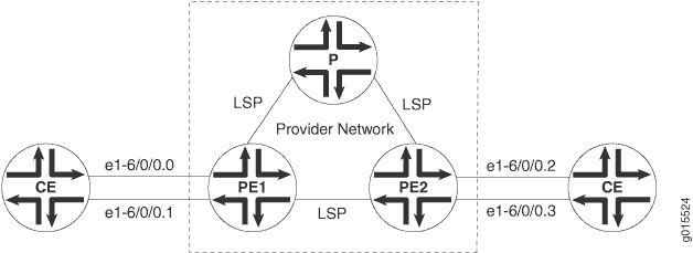
There are many ways to set up an MPLS VPN and direct traffic through it. Figure 1 shows a typical MPLS VPN topology.
There are three primary types of MPLS VPNs: Layer 2 VPNs, Layer 2 circuits, and Layer 3 VPNs. All types of MPLS VPNs share certain components:
The provider edge (PE) routers in the provider's network connect to the customer edge (CE) routers located at customer sites. PE routers support VPN and MPLS label functionality. Within a single VPN, pairs of PE routers are connected through a virtual tunnel, typically a label-switched path (LSP).
Provider routers within the core of the provider's network are not connected to any routers at a customer site but are part of the tunnel between pairs of PE routers. Provider routers support LSP functionality as part of the tunnel support, but do not support VPN functionality.
CE routers are the routers or switches located at the customer site that connect to the provider's network. CE routers are typically IP routers, but they can also be Asynchronous Transfer Mode (ATM), Frame Relay, or Ethernet switches.
All VPN functions are performed by the PE routers. Neither CE routers nor provider routers are required to perform any VPN functions.
MPLS VPN Routing
VPNs tunnel traffic as follows from one customer site to another customer site, using a public network as a transit network, when certain requirements are met:
- Traffic is forwarded by standard IP forwarding from the CE routers to the PE routers.
- The PE routers establish an LSP through the provider network.
- The inbound PE router receives traffic, and it performs a route lookup. The lookup yields an LSP next hop, and the traffic is forwarded along the LSP.
- The traffic reaches the outbound PE router, and the PE router pops the MPLS label and forwards the traffic with standard IP routing.
VRF Instances
A routing instance is a collection of routing tables, interfaces, and routing protocol parameters. The interfaces belong to the routing tables, and the routing protocol parameters control the information in the routing tables. In the case of MPLS VPNs, each VPN has a VPN routing and forwarding (VRF) instance.
A VRF instance consists of one or more routing tables, a derived forwarding table, the interfaces that use the forwarding table, and the policies and routing protocols that determine what goes into the forwarding table. Because each instance is configured for a particular VPN, each VPN has separate tables, rules, and policies that control its operation.
A separate VRF table is created for each VPN that has a connection to a CE router. The VRF table is populated with routes received from directly connected CE sites associated with the VRF instance, and with routes received from other PE routers in the same VPN.
Route Distinguishers
Because a typical transit network is configured to handle more than one VPN, the provider routers are likely to have multiple VRF instances configured. As a result, depending on the origin of the traffic and any filtering rules applied to the traffic, the BGP routing tables can contain multiple routes for a particular destination address. Because BGP requires that exactly one BGP route per destination be imported into the forwarding table, BGP must have a way to distinguish between potentially identical network layer reachability information (NLRI) messages received from different VPNs.
A route distinguisher is a locally unique number that identifies all route information for a particular VPN. Unique numeric identifiers allow BGP to distinguish between routes that are otherwise identical.
Each routing instance that you configure on a PE router must have a unique route distinguisher. There are two possible formats:
as-number:number, where as-number is an autonomous system (AS) number (a 2–byte value) in the range 1 through 65,535, and number is any 4–byte value. We recommend that you use an Internet Assigned Numbers Authority (IANA)-assigned, nonprivate AS number, preferably the ISP or the customer AS number.
ip-address:number, where ip-address is an IP address (a 4–byte value) and number is any 2–byte value. The IP address can be any globally unique unicast address. We recommend that you use the address that you configure in the router-id statement, which is a public IP address in your assigned prefix range.
The route target defines which route is part of a VPN. A unique route target helps distinguish between different VPN services on the same router. Each VPN also has a policy that defines how routes are imported into the VRF table on the router. A Layer 2 VPN is configured with import and export policies. A Layer 3 VPN uses a unique route target to distinguish between VPN routes.
The PE router then exports the route in IBGP sessions to the other provider routers. Route export is governed by any routing policy that has been applied to the particular VRF table. To propagate the routes through the provider network, the PE router must also convert the route to VPN format, which includes the route distinguisher.
When the outbound PE router receives the route, it strips off the route distinguisher and advertises the route to the connected CE router, typically through standard BGP IPv4 route advertisements.
MPLS Exceptions on SRX Series Devices
The MPLS implementation on SRX Series device is similar to MPLS implementations on M Series, T Series, and MX Series routers, with the following exception:
SRX Series devices do not support aggregated Ethernet interfaces. Therefore, aggregated Ethernet interfaces between CE devices and PE routers are not supported for MPLS implementations of Layer 2 VPNs and Layer 2 Circuits on SRX Series devices.