ON THIS PAGE
Active-Active Bridging and VRRP over IRB Functionality Overview
Understanding the Incremented Values of Statistical Counters for Loop-Free MC-LAG Networks
Example: Configuring DHCP Relay on MC- LAG with VRRP on an EX9200 Switch
Configuring Manual and Automatic Link Switchover for MC-LAG Interfaces on MX Series Routers
Example: Configuring Multichassis Link Aggregation in Active-Active Mode
High Availability in Layer 2 Networks Using Active-Active Bridging for MC-LAG
Multichassis Link Aggregation on Logical Systems Overview
On MX Series routers, EX9200, and QFX10000 switches, multichassis link aggregation (MC-LAG) enables a device to form a logical LAG interface with two or more other devices. MC-LAG provides additional benefits over traditional LAG in terms of node-level redundancy, multihoming support, and a loop-free Layer 2 network without running Spanning Tree Protocol (STP). The MC-LAG devices use Inter-Chassis Control Protocol (ICCP) to exchange the control information between two MC-LAG network devices. Starting in Junos OS Release 14.1, you can configure MC-LAG interfaces on logical systems within a router. Starting with Junos OS Release 15.1, you can configure MC-LAG interfaces on logical systems on EX9200 switches.
On QFX10008 switches, Layer 2 and Layer 3 IRB interfaces are not supported under the [edit logical-systems] hierarchy.
To configure ICCP for MC-LAG interfaces on logical systems, include the iccp statement at the [edit logical-systems logical-system-name protocols] hierarchy level. To view ICCP information for MC-LAG on logical systems, use the show iccp logical-system logical-system-name command. To view ARP statistics or remote MAC addresses for the multichassis aggregated Ethernet nodes for all or specified redundancy groups on a logical system, use the show l2-learning redundancy-groups group-name logical-system logical-system-name (arp-statistics | remote-macs) command. To view neighbor discovery (ND) statistical details for multichassis aggregated Ethernet nodes on redundancy groups of a logical group, use the show l2-learning redundancy-groups group-name logical-system logical-system-name nd-statistics command.
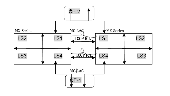
Logical systems enable effective, optimal segregation of a single router or switch into multiple virtual partitions, which can be configured and managed by diversified entities. Logical systems perform a subset of the actions of a physical router or switch and have their own unique routing tables, interfaces, policies, and routing instances. A set of logical systems within a single router or switch can handle the functions previously performed by several small routers or switches. As shown on the right side of Figure 1, a set of logical systems within a single router can handle the functions previously performed by several small routers.
In a network deployment that contains MC-LAG interfaces, you can configure such interfaces on logical systems contained within a router or switch. When you configure multichassis aggregated Ethernet interfaces on a logical system, you must ensure that these interfaces are added with the same multichassis aggregated Ethernet identification number and redundancy group identifier for the MC-LAG on both the peers or devices that are connected by the multichassis aggregated Ethernet interfaces. It is not necessary to specify the same logical system name on both the peers; however, you must ensure that ICCP to associate the routing or switching devices contained in a redundancy group is defined on both the peers within the logical systems of the devices. Such a configuration ensures that all the packets are transmitted using ICCP within the logical system network. The logical system information is added and removed by the ICCP process to prevent each packet from containing the logical system details. This behavior enables multiple disjoint users to employ MC-LAG capabilities within their networks transparently and seamlessly. A unique ICCP definition for a logical system is created, thereby enabling you to completely manage the ICCP parameters on one logical system without the need for access permissions to view other logical system networks on the same device. Configuration of MC-LAG interfaces on logical systems enables MC-LAG to be used across multiple routing tables and switch forwarding tables in active-active and active-standby modes of MC-LAG interfaces.
Because the Layer 2 address learning process supports logical systems, the ARP, neighbor discovery, and MAC synchronization packets that are traversing a multichassis aggregated Ethernet interface use the logical system:routing instance (LS:RI) combination to map the packets to the correct routing instance in a logical system. Link Aggregation Control Protocol (LACP) does not require the LS-RI combination to be identified because it operates on physical interfaces and is unique within a chassis. For a service, in the set of provider edge (PE) routers providing the service, the service ID distinguishes the routing instances in a logical system because it is unique for a logical system across a routing instance. MC-LAG is configured on the aggregated Ethernet (ae-) bundle interface. An ae- interface is a logical interface and is globally unique, which causes the MC-LAG configuration to be exclusive and separate for a router or switch. You can add ae- interfaces in an MC-LAG configuration to be part of a logical system and use it throughout that particular logical system.
Sample Configuration Scenario for MC-LAG on Logical Systems
Consider a sample scenario in which two MX Series routers, MX1 and MX2, are connected using an aggregated Ethernet interface that is enabled with MC-LAG. The peers in an MC-LAG use an interchassis link-protection link (ICL-PL) to replicate forwarding information across the peers. Additionally, ICCP propagates the operational state of MC-LAG members through the ICL-PL. The two PE devices, MX1 and MX2, each have a LAG connected to the CE devices, CE1 and CE2. Four logical systems are defined on each of the PE devices, MX1 and MX2. CE-1 and CE-2 can be part of the same VLAN with the same VLAN ID and located in the same IP subnet for MC-LAG in two different logical systems. All four logical system entities can work independently in MX1 and MX2.
The ICCP process can manage multiple client-server connections with its peer ICCP instances based on the ICCP configuration for the logical system:routing instance (LS-RI) combinations. Each ICCP connection is associated with an LS-RI combination. For example, with two routing instances, IP1 and IP2, on each of the logical systems, LS1 and LS2, the following mapping is performed for ICCP settings:
[ICCP] (LS1) (IP1) < = = > (IP2) (LS1) [ICCP] within LS1 network.
[ICCP] (LS2) (IP1) < = = > (IP2) (LS2) [ICCP] within LS2 network.
An ICCP instance in a logical system is linked with the ICCP instance of the peer logical system. The ICCP application transmits the relevant routing index depending on the LS:RI combination to the BFD process, when BFD is configured in your topology.
Figure 2 shows the interconnection among logical systems on MX Series routers configured with MC-LAG.
The Layer 2 address learning process (l2ald) transmits and receives Address Learning Protocol (ARP), neighbor discovery, and MAC synchronization packets with the LS-RI information. When the peer MAC synchronization packets are received, l2ald decodes the logical system details from the packet and determines whether an identical logical system has been previously created on the router. If a match is found for the logical system, the MAC forwarding entry for the corresponding bridge table for an interface bridge domain is created. If the logical system in the received packet does not match the defined logical system on the device, for the MAC synchronization packet, the default logical instance is used for processing. Similarly, upon receipt of the ARP and neighbor discovery packets, l2ald decapsulates the logical system information from the packets and determines if the corresponding logical instance has been previously created. If a match is found for the logical system, the ARP and neighbor discovery packets are processed according to the Layer 3 index that is unique in the system. The programming kernel entry might not require any logical system information since it is programmed on a Layer 3 index which is unique in the system. If the logical system in the received packet does not match the defined logical system on the device, for the ARP and neighbor discovery packets, the default logical instance is used for processing. The routing instance is determined using the service ID attribute. The logical system information is forwarded to ICCP, which in turn identifies the appropriate ICCP interface for the logical system and sends packets over it.
Guidelines for Configuring MC-LAG on Logical Systems
Keep the following points in mind while configuring MC-LAG interfaces on logical systems:
You cannot use a single chassis to function as a provider edge (PE) device and a customer edge (CE) device in different logical systems.
You cannot use a single chassis to function as two PE devices by configuring logical systems on the chassis and ICCP. ICL links between the two logical systems because the multichassis aggregated Ethernet ID is unique in a router or switch.
Logical interfaces (IFLs) on the same mc-ae interface cannot be configured across multiple logical systems. In other words, in a multichassis link aggregation (MC-LAG) with both logical systems and logical interfaces (such as
mc-ae
ae0 unit 0
), the same logical interface cannot be shared between logical systems.IGMP snooping in MC-LAG topologies with logical systems is not supported.
VPLS and VPN protocols with MC-LAG in active-standby mode is not supported.
Logical system information is not communicated to the peer chassis because this detail is derived from an ICCP instance.
Active-Active Bridging and VRRP over IRB Functionality Overview
Active-active bridging and VRRP over IRB support extends multichassis link aggregation group (MC-LAG) by adding the following functionality to MX Series routers and QFX Series switches:
Interchassis link (ICL) pseudowire interface or Ethernet interface (ICL-PL field) for active-active bridging
Active-active bridging
VRRP over IRB for active-active bridging
A single bridge domain not corresponding to two redundancy group IDs
Benefits of Active-Active Bridging and VRRP over IRB Functionality
Where Can I Use Active-Active Bridging and VRRP over IRB Functionality?
Points to Remember When Configuring MC-LAG Active-Active Bridge Domains
Topologies Supported for MC-LAG Active-Active Bridge Domains
Potential Problems When Configuring MC-LAG Active-Active Bridge Domains
Restrictions When Configuring MC-LAG Active-Active Bridge Domains
How Active-Active Bridging over IRB Functionality Works
Active-Active bridging over IRB functionality uses the address resolution protocol (ARP) Active-Active MC-LAG.
Suppose one of the PE routers issues an ARP request and another PE router gets the response and, because of the aggregated Ethernet distribution logic, the ARP resolution is not successful. Junos OS uses ARP response packet snooping to perform active-active multichassis link aggregation group support, providing synchronization without the need to maintain any specific state.
Address Resolution Protocol Active-Active MC-LAG Support Methodology
Suppose one of the PE routers issues an ARP request and another PE router gets the response and, because of the aggregated Ethernet distribution logic, the ARP resolution is not successful. Junos OS uses ARP response packet snooping to perform active-active multichassis link aggregation group support, providing easy synchronization without the need to maintain any specific state.
Benefits of Active-Active Bridging and VRRP over IRB Functionality
Benefits of active-active bridging and VRRP over IRB functionality include:
An MC-LAG reduces operational expenses by providing active-active links with a LAG, eliminates the need for Spanning Tree Protocol (STP), and provides faster Layer 2 convergence upon link and device failures.
An MC-LAG adds node-level redundancy to the normal link-level redundancy that a LAG provides. An MC-LAG improves network resiliency, which reduces network down time as well as expenses.
In data centers, it is desirable for servers to have redundant connections to the network. You probably want active-active connections along with links from any server to at least two separate routers.
An MC-LAG allows you to bond two or more physical links into a logical link between two routers or between a server and a router, which improves network efficiency. An MC-LAG enables you to load-balance traffic on multiple physical links. If a link fails, the traffic can be forwarded through the other available link, and the logical aggregated link remains in the UP state.
Where Can I Use Active-Active Bridging and VRRP over IRB Functionality?
Active-active bridging and Virtual Router Redundancy Protocol (VRRP) over integrated routing and bridging (IRB) is supported on MX Series routers and QFX Series switches.
MC-LAG Functions in an Active-Active Bridging Domain
The following functions are supported for MC-LAG in an active-active bridging domain:
MC-LAG is supported only between two chassis, using an interchassis link (ICL) pseudowire interface or Ethernet interface (ICL-PL field) for active-active bridging, and active-active bridging VRRP over IRB for active-active bridging.
For VPLS networks, you can configure the aggregated Ethernet (aeX) interfaces on MC-LAG devices with the encapsulation ethernet-vpls statement to use Ethernet VPLS encapsulation on Ethernet interfaces that have VPLS enabled and that must accept packets carrying standard Tag Protocol ID (TPID) values or the encapsulation vlan-vpls statement to use Ethernet VLAN encapsulation on VPLS circuits.
Layer 2 circuit functionalities are supported with ethernet-ccc as the encapsulation mode.
Network topologies in a triangular and square pattern are supported. In a triangular network design, with equal-cost paths to all redundant nodes, slower, timer-based convergence can possibly be prevented. Instead of indirect neighbor or route loss detection using hellos and dead timers, you can identify the physical link loss and denote a path as unusable and reroute all traffic to the alternate equal-cost path. In a square network design, depending on the location of the failure, the routing protocol might converge to identify a new path to the subnet or the VLAN, causing the convergence of the network to be slower.
Interoperation of Link Aggregation Control Protocol (LACP) for MC-LAG devices is supported. LACP is one method of bundling several physical interfaces to form one logical interface. When LACP is enabled, the local and remote sides of the aggregated Ethernet links exchange protocol data units (PDUs), which contain information about the state of the link. You can configure Ethernet links to actively transmit PDUs, or you can configure the links to passively transmit them, sending out LACP PDUs only when the links receive the PDUs from another link. One side of the link must be configured as active for the link to be up.
Active-standby mode is supported using LACP. When an MC-LAG operates in the active-standby mode, one of the router’s ports only becomes active when failure is detected in the active links. In this mode, the provider edge (PE) routers perform an election to determine the active and standby routers.
Configuration of the pseudowire status type length variable (TLV) is supported. The pseudowire status TLV is used to communicate the status of a pseudowire back and forth between two PE routers. The pseudowire status negotiation process ensures that a PE router reverts back to the label withdraw method for pseudowire status if its remote PE router neighbor does not support the pseudowire status TLV.
The MC-LAG devices use Inter-Chassis Control Protocol (ICCP) to exchange the control information between two MC-LAG network devices.
Points to Remember When Configuring MC-LAG Active-Active Bridge Domains
Keep the following points in mind when you configure MC-LAG in an active-active bridging domain:
A single bridge domain cannot be associated with two redundancy groups. You cannot configure a bridge domain to contain logical interfaces from two different multichassis aggregated Ethernet interfaces and associate them with different redundancy group IDs by using the redundancy group group-id statement at the [edit interfaces aeX aggregated-ether-options] hierarchy level.
You must configure logical interfaces in a bridge domain from a single multichassis aggregated Ethernet interface and associate it with a redundancy group. You must configure a service ID by including the service-id vid statement at the [edit bridge-domains bd-name] hierarchy level for multichassis aggregated Ethernet interfaces if you configure logical interfaces on multichassis aggregated Ethernet interfaces that are part of the bridge domain.
More Data Traffic Forwarding Rules
In active-active bridging and VRRP over IRB topographies, network interfaces are categorized into three different interface types, as follows:
Based on incoming and outgoing interface types, some constraints are added to the Layer 2 forwarding rules for MC-LAG configurations, as described in the data traffic forwarding rules. Note that if only one of the MC-LAG member link is in the UP state, it is considered an S-Link.
The following data traffic forwarding rules apply:
- When an MC-LAG network receives a packet from a local
MC-Link or S-Link, the packet is forwarded to other local interfaces,
including S-Links and MC-Links based on the normal Layer 2 forwarding
rules and on the configuration of the mesh-group and no-local-switching statements. If MC-Links and S-Links are
in the same mesh group and their no-local-switching statements
are enabled, the received packets are only forwarded upstream and
not sent to MC-Links and S-Links.
Note The functionality described in Rule 2 is not supported.
- The following circumstances determine whether or not an
ICL receives a packet from a local MC-Link or S-Link:
If the peer MC-LAG network device has S-Links or MC-LAGs that do not reside on the local MC-LAG network device
Whether or not interfaces on two peering MC-LAG network devices are allowed to talk to each other only if both a. and b. are true. Traffic is always forwarded to the ICL.
- When an MC-LAG network receives a packet from the ICL, the packet is forwarded to all local S-Links and active MC-LAGs that do not exist in the MC-LAG network that the packet comes from.
Note In certain cases, for example the topology shown in Figure 3, there could be a loop caused by the ICL. To break the loop, one of the following mechanisms could be used:The topology shown in Figure 3 is not supported.
Run certain protocols, such as STP. In this case, whether packets received on one ICL are forwarded to other ICLs is determined by using Rule 3.
Configure the ICL to be fully meshed among the MC-LAG network devices. In this case, traffic received on the ICL would not be forwarded to any other ICLs.
In either case, duplicate packets could be forwarded to the MC-LAG clients. Consider the topology shown in Figure 3, where if network routing instance N1 receives a packet from ge-0/0/0.0, it could be flooded to ICL1 and ICL3.
When receiving from ICL1 and ICL3, network routing instances N3 and N2 could flood the same packet to MCL2, as shown in Figure 3. To prevent this from happening, the ICL designated forwarder should be elected between MC-LAG peers, and traffic received on an ICL could be forwarded to the active-active MC-LAG client by the designated forwarder only.
Figure 3: Loop Caused by the ICL Links 
- When received from an ICL, traffic should not be forwarded to the core-facing client link connection between two provider edge (PE) devices (MC-Link) if the peer chassis's (where the traffic is coming from) MC-Link is UP.
How to Configure MC-LAG Active-Active Bridge Domains
For a MC-LAG configured in an active-active bridge domain and with VRRP configured over an IRB interface, you must include the accept-data statement at the [edit interfaces interface-name unit logical-unit-number family inet address address vrrp-group group-id] hierarchy level to enable the router that functions as the master router to accept all packets destined for the virtual IP address.
On an MC-LAG, if you modify the source MAC address to be the virtual MAC address, you must specify the virtual IP address as the source IP address instead of the physical IP address. In such a case, the accept-data option is required for VRRP to prevent ARP from performing an incorrect mapping between IP and MAC addresses for customer edge (CE) devices. The accept-data attribute is needed for VRRP over IRB interfaces in MC-LAG to enable OSPF or other Layer 3 protocols and applications to work properly over multichassis aggregated Ethernet (mc-aeX) interfaces.
On an MC-LAG, the unit number associated with aggregated Ethernet interfaces on provider edge router PE1 must match the unit number associated with aggregated Ethernet interfaces on provider edge router PE2. If the unit numbers differ, MAC address synchronization does not happen. As a result, the status of the MAC address on the remote provider edge router remains in a pending state.
If you are using the VRRP over IRB or RVI method to enable Layer 3 functionality, you must configure static ARP entries for the IRB or RVI interface of the remote MC-LAG peer to allow routing protocols to run over the IRB or RVI interfaces.
MAC Address Management
If an MC-LAG is configured to be active-active, upstream and downstream traffic could go through different MC-LAG network devices. Since the media access control (MAC) address is learned only on one of the MC-LAG network devices, the reverse direction's traffic could be going through the other MC-LAG network and be flooded unnecessarily. Also, a single-homed client's MAC address is only learned on the MC-LAG network device it is attached to. If a client attached to the peer MC-LAG network needs to communicate with that single-homed client, then traffic would be flooded on the peer MC-LAG network device. To avoid unnecessary flooding, whenever a MAC address is learned on one of the MC-LAG network devices, it gets replicated to the peer MC-LAG network device. The following conditions should be applied when MAC address replication is performed:
MAC addresses learned on an MC-LAG of one MC-LAG network device should be replicated as learned on the same MC-LAG of the peer MC-LAG network device.
MAC addresses learned on single-homed customer edge (CE) clients of one MC-LAG network device should be replicated as learned on the ICL-PL interface of the peer MC-LAG network device.
MAC addresses learned on MC-LAG VE clients of one MC-LAG network device should be replicated as learned on the corresponding VE interface of the peer MC-LAG network device.
MAC address learning on an ICL is disabled from the data path. It depends on software to install MAC addresses replicated through Inter-Chassis Control Protocol (ICCP).
MAC Aging
MAC aging support in Junos OS extends aggregated Ethernet logic for a specified MC-LAG. A MAC address in software is deleted until all Packet Forwarding Engines have deleted the MAC address. In the case of an MC-LAG, a remote provider edge is treated as a remote Packet Forwarding Engine and has a bit in the MAC data structure.
Layer 3 Routing
In general, when an MC-LAG is configured to provide Layer 3 routing functions to downstream clients, the MC-LAG network peers should be configured to provide the same gateway address to the downstream clients. To the upstream routers, the MC-LAG network peers could be viewed as either equal-cost multipath (ECMP) or two routes with different preference values.
Junos OS supports active-active MC-LAGs by using VRRP over IRB. Junos OS also supports active-active MC-LAGs by using IRB MAC address synchronization. You must configure IRB using the same IP address across MC-LAG peers. IRB MAC synchronization is supported on 32-bit interfaces and interoperates with earlier MPC and MIC releases.
To ensure that Layer 3 operates properly, instead of dropping the Layer 3 packet, the VRRP backup attempts to perform routing functions if the packet is received on an MC-LAG. A VRRP backup sends and responds to Address Resolution Protocol (ARP) requests.
For ARP, the same issue exists as with Layer 2 MAC addresses. Once ARP is learned, it must be replicated to the MC-LAG through ICCP. The peer must install an ARP route based on the ARP information received through ICCP.
For ARP aging, ARP requests on the MC-LAG peers can be aged out independently.
Topologies Supported for MC-LAG Active-Active Bridge Domains
The topologies shown in Figure 4 and Figure 5 are supported. These figures use the following abbreviations:
Aggregated Ethernet (AE)
Interchassis link (ICL)
Multichassis link (MCL)
Potential Problems When Configuring MC-LAG Active-Active Bridge Domains
When configured to be active-active, the client device load-balances the traffic to the peering MC-LAG network devices. In a bridging environment, this could potentially cause the following problems:
Traffic received on the MC-LAG from one MC-LAG network device could be looped back to the same MC-LAG on the other MC-LAG network device.
Duplicated packets could be received by the MC-LAG client device.
Traffic could be unnecessarily forwarded on the interchassis link.
To better illustrate the problems listed, consider Figure 6, where an MC-LAG device MCL1 and single-homed clients ge-0/0/0.0 and ge-1/0/0.0 are allowed to talk to each other through an ICL. These problems could occur:
Traffic received on network routing instance N1 from MCL1 could be flooded to ICL to reach network routing instance N2. Once it reaches network routing instance N2, it could flood again to MCL1.
Traffic received on interface ge-0/0/0.0 could be flooded to MCL1 and ICL on network routing instance N1. Once network routing instance N2 receives such traffic from ICL, it could again be flooded to MCL1.
If interface ge-1/0/0.0 does not exist on network routing instance N2, traffic received from interface ge-0/0/0.0 or MCL1 on network routing instance N1 could be flooded to network routing instance N2 through ICL unnecessarily since interface ge-0/0/0.0 and MCL1 could reach each other through network routing instance N1.
Restrictions When Configuring MC-LAG Active-Active Bridge Domains
In an IPv6 network, you cannot configure an MC-LAG in an active-active bridge domain if you specified the vlan-id none statement at the [edit bridge-domain bd-name] hierarchy level. The vlan-id none statement that enables the removal of the incoming VLAN tags identifying a Layer 2 logical interface when packets are sent over VPLS pseudowires is not supported for IPv6 packets in an MC-LAG.
The following functionality is not supported for MC-LAG active-active bridge domains:
Virtual private LAN service (VPLS) within the core
Bridged core
Topology as described in Rule 4 of More Data Traffic Forwarding Rules
Routed multichassis aggregated Ethernet interface, where the VRRP backup router is used in the edge of the network
Track object, where in the case of an MC-LAG, the status of the uplinks from the provider edge can be monitored, and the MC-LAG can act on the status
Mixed mode (active-active MC-LAG is supported on MX Series routers with MPC or MIC interfaces only)
All interfaces in the bridge domain that are multichassis aggregated Ethernet active-active must be on MPCs or MICs.
The topologies shown in Figure 7, Figure 8, and Figure 9 are not supported:
A redundancy group cannot span more than two routers.
IGMP Snooping on Active-Active MC-LAG
IGMP Snooping on Active-Active MC-LAG
For multicast to work in an active-active MC-LAG scenario, the typical topology is as shown in Figure 10 and Figure 11 with interested receivers over S-links and MC-Links. Starting in Junos OS Release 11.2, support is extended for sources connected over the Layer 2 interface.
If an MC-LAG is configured to be active-active, reports from MC-LAG clients could reach any of the MC-LAG network device peers. Therefore, the IGMP snooping module needs to replicate the states such that the Layer 2 multicast route state on both peers are the same. Additionally for S-Link clients, snooping needs to replicate these joins to its snooping peer, which in the case of Layer 3 connected source, passes this information to the PIM on IRB to enable the designated router to pull traffic for these groups,
The ICL should be configured as a router facing interface. For the scenario where traffic arrives through a Layer 3 interface, it is a requirement to have PIM and IGMP enabled on the IRB interface configured on the MC-LAG network device peers.
With reference to Figure 10, either Device N1 or N2 becomes a designated router (for this example, N1 is the designated router). Router N1 therefore pulls the multicast traffic from the core. Once multicast data hits the network Device N1, the data is forwarded based on the snooping learned route.
For MC-Link clients, data is forwarded through N1. In the case of failover of the MC-Links, the data reaches the client through N2. For S-Link clients on N1, data would be forwarded through normal snooping routes.
For S-Link clients on N2, data is forwarded through the ICL interface. Layer 2 multicast routes on N1 do not show these groups unless there is interest for the same group over MC-Links or over S-Links on N1. For the IRB scenario, the IGMP membership and Layer 3 multicast route on N1 does however show these groups learned over the IRB interface.
Therefore, for a case where a specific group interest is only on the S-Link on N2, data arriving on N1 reaches N2 through the default route, and the Layer 2 multicast route on N2 has the S-Link in the outgoing interface list.
In Figure 11, MCL1 and MCL2 are on different devices, and the multicast source or IGMP querier is connected through MCL2. The data forwarding behavior seen is similar to that explained for multicast topology with source connected through Layer 3.
IGMP snooping should not be configured in proxy mode. There should be no IGMP hosts or IGMP or PIM routers sitting on the ICL interface.
Up and Down Event Handling
The following conditions apply to up and down event handling:
If the Inter-Chassis Control Protocol (ICCP) connection is UP but the ICL interface goes DOWN, the router configured as the backup brings down all the multichassis aggregated Ethernet interfaces shared with the peer that is connected to ICL. This ensures that there are no loops in the network. Otherwise, both PEs become PIM-designated routers and, hence, forward multiple copies of the same packet to the customer edge.
If the ICCP connection is UP and the ICL comes UP, the router configured as the backup brings up the multichassis aggregated Ethernet interfaces shared with the peer.
If both the ICCP connection and the ICL are DOWN, the router configured as the backup brings up the multichassis aggregated Ethernet interfaces shared with the peer.
The Layer 2 address learning process (l2ald) does not store the information about a MAC address learned from a peer in the kernel. If l2ald restarts, and if the MAC address was not learned from the local multichassis aggregated Ethernet interface, l2ald clears the MAC addresses, which causes the router to flood the packets destined to this MAC address. This behavior is similar to that in a Routing Engine switchover. (Note that currently l2ald runs on a Routing Engine only when it is a master). Also, during the time l2ald is DOWN, ARP packets received from an ICCP peer are dropped. ARP retry takes care of this situation. This is the case with Routing Engine switchover, too.
If ICCP restarts, l2ald does not identify that a MAC address was learned from a peer and, if the MAC address was learned only from the peer, that MAC address is deleted, and the packets destined to this MAC address are flooded.
Inter-Chassis Control Protocol
Inter-Chassis Control Protocol (ICCP) is used to synchronize configurations, states, and data.
ICCP supports the following types of state information:
MC-LAG members and their operational states
Single-homed members and their operational states
ICCP supports the following application database synchronization parameters:
MAC addresses learned and to be aged
ARP information learned over IRB
Inter-Chassis Control Protocol Message
ICCP messages and attribute-value pairs (AVPs) are used for synchronizing MAC address and ARP information.
Understanding the Incremented Values of Statistical Counters for Loop-Free MC-LAG Networks
In an MC-LAG in an active-active bridging domain, the output of the following command displays the MC-LAG color counters to be continuously increasing. This increase in the statistical count is an expected behavior because the MC-LAG color attribute or counter functions as a loop prevention mechanism.
request pfe execute target fpc0 command "show jnh 0 exceptions" |grep color
GOT: mc lag color                       DISC(88)   554712463 144488623417
request pfe execute target fpc0 command "show jnh 0 exceptions" |grep color
GOT: mc lag color                       DISC(88)   554712747 144488664296
The exception table stored in the Packet Forwarding Engine contains a list of counters as displayed in the following example output:
request pfe execute target fpc0 command "show jnh 0 exceptions"
SENT: Ukern command: show jnh 0 exceptions
GOT: Reason                             Type         Packets      Bytes
GOT: ==================================================================
GOT: Ucode Internal
GOT: ----------------------
GOT: mcast stack overflow               DISC(33)           0          0
GOT: sample stack error                 DISC(35)           0          0
GOT: undefined nexthop opcode           DISC(36)           0          0
GOT: internal ucode error               DISC(37)           0          0
GOT: invalid fabric hdr version         DISC(41)           0          0
GOT:
GOT: PFE State Invalid
GOT: ----------------------
GOT: sw error                           DISC(64)   803092438 59795128826
GOT: child ifl nonlocal to pfe          DISC(85)           0          0
GOT: invalid fabric token               DISC(75)         179      42346
GOT: unknown family                     DISC(73)           0          0
GOT: unknown vrf                        DISC(77)           0          0
GOT: iif down                           DISC(87)           0          0
GOT: unknown iif                        DISC( 1)
GOT: invalid stream                     DISC(72)           0          0
GOT: egress pfe unspecified             DISC(19)       10889    1536998
GOT: invalid L2 token                   DISC(86)          26       1224
GOT: mc lag color                       DISC(88)   554693648
144486028726<<<<<<<<<<<<<<<<<<<<<<<<
GOT: dest interface non-local to pfe    DISC(27)  10939253797 2078273071209
GOT: invalid inline-svcs state          DISC(90)           0          0
GOT: nh id out of range                 DISC(93)           0          0
GOT: invalid encap                      DISC(96)           0          0
GOT: replication attempt on empty irb   DISC(97)           0          0
GOT: invalid selector entry             DISC(98)           0          0
GOT:
GOT:
GOT: Packet Exceptions
GOT: ----------------------
GOT: bad ipv4 hdr checksum              DISC( 2)
GOT: non-IPv4 layer3 tunnel             DISC( 4)           0          0
GOT: GRE unsupported flags              DISC( 5)           0          0
GOT: tunnel pkt too short               DISC( 6)           0          0
GOT: tunnel hdr too long                DISC( 7)           0          0
GOT: bad IPv6 options pkt               DISC( 9)           0          0
GOT: bad IP hdr                         DISC(11)           0          0
GOT: bad IP pkt len                     DISC(12)           0          0
GOT: L4 len too short                   DISC(13)
GOT: invalid TCP fragment               DISC(14)           0          0
GOT: mtu exceeded                       DISC(21)           0          0
GOT: frag needed but DF set             DISC(22)           0          0
GOT: ttl expired                        PUNT( 1)           9        769
GOT: IP options                         PUNT( 2)          16        512
GOT: xlated l2pt                        PUNT(14)           0          0
GOT: control pkt punt via ucode         PUNT( 4)           0          0
GOT: frame format error                 DISC( 0)
GOT: tunnel hdr needs reassembly        PUNT( 8)           0          0
GOT: GRE key mismatch                   DISC(76)           0          0
GOT: my-mac check failed                DISC(28)
GOT: frame relay type unsupported       DISC(38)           0          0
GOT: IGMP snooping control packet       PUNT(12)           0          0
GOT: bad CLNP hdr                       DISC(43)           0          0
GOT: bad CLNP hdr checksum              DISC(44)           0          0
GOT: Tunnel keepalives                  PUNT(58)           0          0
GOT:
GOT:
GOT: Bridging
GOT: ----------------------
GOT: lt unknown ucast                   DISC(84)           0          0
GOT: dmac miss                          DISC(15)           0          0
GOT: mac learn limit exceeded           DISC(17)           0          0
GOT: static mac on unexpected iif       DISC(18)           0          0
GOT: no local switching                 DISC(20)           0          0
GOT: bridge ucast split horizon         DISC(26)       39458   13232394
GOT: mcast smac on bridged iif          DISC(24)        1263     200152
GOT: bridge pkt punt                    PUNT( 7)           0          0
GOT: iif STP blocked                    DISC( 3)
GOT: oif STP blocked                    DISC(31)
GOT: vlan id out of oif's range         DISC(32)
GOT: mlp pkt                            PUNT(11)    15188054  440453569
GOT: input trunk vlan lookup failed     DISC(91)           0          0
GOT: output trunk vlan lookup failed    DISC(92)           0          0
GOT: LSI/VT vlan validation failed      DISC(94)           0          0
GOT:
GOT:
GOT: Firewall
GOT: ----------------------
GOT: mac firewall                       DISC(78)
GOT: firewall discard                   DISC(67)           0          0
GOT: tcam miss                          DISC(16)           0          0
GOT: firewall reject                    PUNT(36)      155559   59137563
GOT: firewall send to host              PUNT(54)           0          0
GOT: firewall send to host for NAT      PUNT(59)           0          0
GOT:
GOT:
GOT: Routing
GOT: ----------------------
GOT: discard route                      DISC(66)     1577352   82845749
GOT: dsc ifl discard route              DISC(95)           0          0
GOT: hold route                         DISC(70)       21130    1073961
GOT: mcast rpf mismatch                 DISC( 8)           0          0
GOT: resolve route                      PUNT(33)        2858     154202
GOT: control pkt punt via nh            PUNT(34)    51807272 5283911584
GOT: host route                         PUNT(32)    23473304 1370843994
GOT: ICMP redirect                      PUNT( 3)           0          0
GOT: mcast host copy                    PUNT( 6)           0          0
GOT: reject route                       PUNT(40)        1663     289278
GOT: link-layer-bcast-inet-check        DISC(99)           0          0
GOT:
Consider a sample deployment in which two provider edge (PE) routers, PE1 and PE2, are connected with an aggregated Ethernet interface, ae0. respectively. Multichassis link aggregation groups (MC-LAGs) are used between PE1 and PE2 to form a logical LAG interface between the two controllers. PE1 and PE2 in an MC-LAG use an interchassis control link-protection link (ICL-PL) to replicate forwarding information across the peers.
Inter-Chassis Control Protocol (ICCP) messages are sent between the two PE devices. In this example, you configure an MC-LAG across two routers, consisting of two aggregated Ethernet interfaces, an interchassis control link-protection link (ICL-PL), multichassis protection link for the ICL-PL, and ICCP for the peers hosting the MC-LAG.
The PE1 router is connected using another aggregated Ethernet interface, ae3, to a host, H1, and to another MC-LAG host called C1. MC-LAG is enabled on the ae3 interface.
Traffic received on PE1 from MC-LAG C1 can be flooded over the ICL to reach PE2. When the packets arrive at PE2, they can be flooded back to MC- LAG C1. Traffic sent by the single-homed host H1 can be flooded to MC-LAG C1 and the ICL on PE1. When PE2 receives such traffic from ICL, it can be again flooded to MC-LAG C1. To protect the MC-LAG topology from such loops, the MC-LAG color capability is implemented. This functionality is applied on the ingress of the ICL link. Therefore, when PE2 receives a packet from PE1, it sets the MC-LAG color as active or turns it on. When PE2 requires to flood the packet towards the MC-LAG link, it verifies whether the MC-LAG color bit is set or tagged as on. If the color is set, it drops the packet on the egress interface of MC-LAG ae3 member link interfaces and the mc-lag color counter in the jnh exceptions is incremented.
Such a behavior of increase in counter value is an expected condition in an MC-LAG configured in an active/active bridging domain and when any form of traffic that needs to be flooded, such as ARP broadcast or multicast traffic, traverses the network.
Every VLAN might drop some packets to prevent loops and such a drop of packets might not be specific to a VLAN.
Sometimes, on both MC LAGs of the MX Series routers, you might notice that the counter increases on FPC0 and FPC2, but it does not increase on FPC2 as illustrated in the following sample output:
request pfe execute target fpc0 command "show jnh 0 exceptions" |grep color
GOT: mc lag color                       DISC(88)   558477875 144977739683
request pfe execute target fpc1 command "show jnh 0 exceptions" |grep color
GOT: mc lag color                       DISC(88)           0          0
request pfe execute target fpc2 command "show jnh 0 exceptions" |grep color
GOT: mc lag color                       DISC(88)   518499257 119130527834
This behavior occurs because on an MX Series router with a 16-port 10-Gigabit Ethernet MPC (16x10GE 3D MPC), there are four Packet Forwarding Engines for each MPC. If you examine one Packet Forwarding Engine in FPC 0, 1, and 2, PFE1 in FPC1 does not have any interfaces which are member of MC-LAG. It might contain interfaces in other aggregated Ethernet interfaces that are are not part of MC-LAG. Therefore, to obtain the correct counter statistics, you must examine the other Packet Forwarding Engines by entering the request pfe execute target fpc0 command "show jnh X exceptions" |grep color command where X can be 0, 1, 2, or 3.
When the counter named dest interface non-local to pfe is increasing, it is a desired behavior when aggregated Ethernet interfaces are split over more than one FPC. Consider an example in which an ae5 interface contains the following member links: xe-0/1/0 on (FPC0) and xe-1/1/0 (FPC1) Based on the hash algorithm, traffic must be split between these two links. The hash algorithm is applied on the ingress FPC and performs an operation where it marks each packet through which FPC must be forwarded (FPC0 or FPC1). Then the packet is sent to the fabric. From the fabric, all of traffic is sent to both FPCs 0 and 1. On FPC0, the microkernel analyzes the packet and determines whether the packet needs to be forwarded by the local interface (local to pfe) or whether this packet has already been forwarded through FPC1 (non-local to pfe). If the packet has been already forwarded, the packet is dropped and the non-local to pfe counter is incremented.
Configuring Active-Active Bridging and VRRP over IRB in Multichassis Link Aggregation on MX Series Routers
The following sections describe the configuration of active-active bridging and VRRP over IRB in a multichassis link aggregation (MC-LAG) :
Configuring MC-LAG
An MC-LAG is composed of logical link aggregation groups (LAGs) and is configured under the [edit interfaces aeX] hierarchy, as follows:
The mode active-active statement is valid only if encapsulation is an ethernet-bridge or extended-vlan-bridge.
Use the mode statement to specify if an MC-LAG is active-standby or active-active. If the ICCP connection is UP and ICL comes UP, the router configured as standby brings up the multichassis aggregated Ethernet interfaces shared with the peer.
Using multi-chassis-protection at the physical interface level is a way to reduce the configuration at the logical interface level.
If there are n+1 logical interfaces under ae0, from ae0.0 through ae0.n, there are n+1 logical interfaces under ge-0/0/0 as well, from ge-0/0/0.0 through ge-0/0/0.n, each ge-0/0/0 logical interface is a protection link for the ae0 logical interface.
A bridge domain cannot have multichassis aggregated Ethernet logical interfaces that belong to different redundancy groups.
Configuring the Interchassis Link-Protection Link
The interchassis link-protection link (ICL-PL) provides redundancy when a link failure (for example, an MC-LAG trunk failure) occurs on one of the active links. The ICL-PL is an aggregated Ethernet interface. You can configure only one ICL-PL between the two peers, although you can configure multiple MC-LAGs between them.
The ICL-PL assumes that interface ge-0/0/0.0 is used to protect interface ae0.0 of MC-LAG-1:
The protection interface can be an Ethernet type interface such as ge or xe, or an aggregated Ethernet (ae) interface.
Configuring Multiple Chassis
A top-level hierarchy is used to specify a multichassis-related configuration, as follows:
This example specifies interface ge-0/0/0 as the multichassis protection interface for all the multichassis aggregated Ethernet interfaces which are also part of the peer. This can be overridden by specifying protection at the physical interface level and the logical interface level.
Configuring the Service ID
You must configure the same unique network-wide configuration for a service in the set of PE routers providing the service. You can configure the service IDs under the level of the hierarchies shown in the following examples:
Global Configuration (Default Logical System)
Logical Systems
Using a service name per bridge domain is not supported.
The bridge-level service ID is required to link related bridge domains across peers, and should be configured with the same value. The service-id values share the name space across all bridging and routing instances, and across peers. Thus, duplicate values for service IDs are not permitted across these entities.
The service ID at the bridge domain level is mandatory for type non-single VLAN bridge domains. The service ID is optional for bridge domains with a VLAN identifier (VID) defined. If no service ID is defined in the latter case, it is picked up from the service ID configuration for that routing instance.
When this default routing instance (or any other routing instance) which contains a bridge domain containing a multichassis aggregated Ethernet interface is configured, you must configure a global-level switch-options service-id number, irrespective of whether the contained bridge domains have specific service IDs configured.
In the sample illustration shown in Figure 12, network routing instances N1 and N2, both for the same service ID, are configured with same service ID in both N1 and N2. Use of a name string instead of a number is not supported.
The following configuration restrictions apply:
The service ID must be configured when the multichassis aggregated Ethernet interface is configured and a multichassis aggregated Ethernet logical interface is part of a bridge domain. This requirement is enforced.
A single bridge domain cannot correspond to two redundancy group IDs.
In Figure 13, it is possible to configure a bridge domain consisting of logical interfaces from two multichassis aggregated Ethernet interfaces and map them to a separate redundancy group ID, which is not supported. A service must be mapped one-to-one with the redundancy group providing the service. This requirement is enforced.
Figure 13: Bridge Domain with Logical Interfaces from Two Multichassis Aggregated Ethernet Interfaces 
To display the multichassis aggregated Ethernet configuration, use the show interfaces mc-ae command. For more information, see the CLI Explorer.
Configuring IGMP Snooping for Active-Active MC-LAG
For the multicast solution to work, the following must be configured:
The multichassis protection link must be configured as a router-facing interface.
[edit bridge-domain bd-name]protocols {igmp-snooping {interface ge-0/0/0.0 {multicast-router-interface;}}}In this example, ge-0/0/0.0 is an ICL interface.
The multichassis-lag-replicate-state statement options must be configured under the multicast-snooping-options statement for that bridge domain.
Snooping with active-active MC-LAG is only supported in non-proxy mode.
Configuring IGMP Snooping in MC-LAG Active-Active Mode
You can use the bridge-domain statement's service-id option to specify the multichassis aggregated Ethernet configuration on MX240 routers, MX480 routers, MX960 routers and QFX Series switches.
The service-id statement is mandatory for non-single VLAN type bridge domains (none, all, or vlan-id-tags:dual).
The statement is optional for bridge domains with a VID defined.
If no service-id is defined in the latter case, it is picked up from the round-trip time’s (RTT's) service-id configuration.
The bridge-level service-id is required to link related bridge domains across peers, and should be configured with the same value.
The service-id values share the name space across all bridging and routing instances, and across peers. Thus, duplicate service-id values are not permitted across these entities.
A change of bridge service-id is considered catastrophic, and the bridge domain is changed.
This procedure allows you to enable or disable the replication feature.
To configure IGMP snooping in MC-LAG active-active mode :
- Use the multichassis-lag-replicate-state statement
at the [edit multicast-snooping-options] hierarchy level
in the master instance.multicast-snooping-options {...multichassis-lag-replicate-state; # REQUIRED}
- Use the interface icl-intf-name statement at the [edit protocols igmp-snooping] hierarchy level, as shown in the following example:protocols {igmp-snooping {interface icl-intf-name {multicast-router-interface;}}}
Note For QFX use the following configuration:
protocols {igmp-snooping {vlan vlan_name{}interface icl-intf-name {multicast-router-interface;}}}The interchassis link, interface icl-intf-name, of the learning domain should be a router-facing interface.
Example: Configuring DHCP Relay on MC- LAG with VRRP on an EX9200 Switch
This example shows how to configure Dynamic Host Configuration Protocol (DHCP) relay on EX9200 switches with the multichassis link aggregation (MC-LAG) feature using Virtual Router Redundancy Protocol (VRRP).
Requirements
This example uses the following hardware and software components:
Junos OS Release 12.3 or later for EX Series
Two EX9200 switches
Before you configure DHCP relay, be sure that you understand how to:
Configure MC-LAG and verify that MC-LAG and ICCP is up and running
To complete the configuration, enable VRRP by completing the following steps for each MC-LAG:
Create an integrated routing and bridging (IRB) interface.
Create a VRRP group and assign a virtual IP address that is shared between each switch in the VRRP group.
Enable a member of a VRRP group to accept all packets destined for the virtual IP address if it is the master in the VRRP group.
Configure Layer 3 connectivity between the VRRP groups.
Overview
In this example, you configure DHCP relay with MC-LAG across two switches consisting of two EX9200 switches, an interchassis link-protection link (ICL-PL), multichassis protection link for the ICL-PL, ICCP for the peers hosting the MC-LAG, and Layer 3 connectivity between MC-LAG peers. Layer 3 connectivity is required for ICCP.
On EX9200 switches, dynamic ARP resolution is not supported over inter-chassis control links (ICLs). As a workaround, you can configure static ARP on both ends of the ICL.
Topology
Table 1: Components of the Topology for Configuring DHCP Relay
Hostname | Hardware | |
|---|---|---|
Switch EX9200-A | EX9200 switch | |
Switch EX9200-B | EX9200 switch |
Configuration
CLI Quick Configuration
To quickly configure this example, copy the following commands, paste them in a text file, remove any line breaks, change any details necessary to match your network configuration, copy and paste the commands into the CLI at the [edit] hierarchy level, and then enter commit from configuration mode.
Switch A and Switch B
Step-by-Step Procedure
To configure DHCP relay on both Switch A and Switch B:
- Configure forward snooped (unicast) packets on the interfaces.[edit forwarding-options dhcp-relay]
user@switch# set forward-snooped-clients all-interfaces - Create a DHCP server group. A DHCP server group can include
1 through 5 DHCP server IP addresses.[edit forwarding-options dhcp-relay]
user@switch# set server-group GVP-DHCP 10.168.61.5 - Allow the creation of a binding entry using snooped (unicast)
clients.[edit forwarding-options dhcp-relay]
user@switch# set overrides allow-snooped-clients - Apply a DHCP relay agent configuration to the named group
of DHCP server addresses.[edit forwarding-options dhcp-relay ]
user@switch# set active-server-group GVP-DHCP - Create a DHCP relay group that includes at least one interface.
DHCP relay runs on the interfaces defined in DHCP groups.
[edit forwarding-options dhcp-relay]
user@switch# set group Floor1 interface irb.2540 - Configure the relay agent to suppress the installation
of ARP and route entries for corresponding client binding.[edit forwarding-options dhcp-relay]
user@switch# set route-suppression destination
Results
From configuration mode, confirm your configuration by entering the show forwarding-options dhcp-relay command on both Switch A and Switch B. If the output does not display the required configuration, repeat the instructions in this example to correct the configuration.
Overwriting Address Information
Step-by-Step Procedure
We recommend that you configure the DHCP relay agent to change the gateway IP address (giaddr) field in packets that it forwards between a DHCP client and a DHCP server.
To overwrite the address of every DHCP packet with the address of the DHCP relay agent before forwarding the packet to the DHCP server.
- Specify that you want to configure override options.[edit forwarding-options dhcp-relay]
user@hots# set overrides - Specify that the address of DHCP packets is overwritten.[edit forwarding-options dhcp-relay overrides]
user@host# set always-write-giaddr
Verification
Confirm that the configuration is working properly.
Verifying That DHCP Relay Binding Is Occurring
Purpose
Verify that address bindings in the DHCP client table are being displayed.
Action
root@switchA# show dhcp relay binding detailClient IP Address: 10.168.103.20 Hardware Address: 84:18:88:a8:ca:80 State: BOUND(RELAY_STATE_BOUND) Lease Expires: 2013-10-03 12:17:43 CEST Lease Expires in: 85829 seconds Lease Start: 2013-10-02 10:48:34 CEST Last Packet Received: 2013-10-02 12:17:43 CEST Incoming Client Interface: ae0.0(irb.2540) Server Ip Address: 10.168.61.5 Server Interface: none Bootp Relay Address: 10.168.103.2 Session Id: 29
root@switchB# show dhcp relay binding detailClient IP Address: 10.168.103.20 Hardware Address: 84:18:88:a8:ca:80 State: BOUND(RELAY_STATE_BOUND) Lease Expires: 2013-10-03 12:17:43 CEST Lease Expires in: 86228 seconds Lease Start: 2013-10-02 10:48:34 CEST Last Packet Received: 2013-10-02 10:48:34 CEST Incoming Client Interface: ae11.0(irb.2540) Server Ip Address: 10.168.61.5 Server Interface: none Bootp Relay Address: 10.168.103.2 Session Id: 16
Meaning
The field State indicates the state of the DHCP relay address binding table on the DHCP client. The state BOUND indicates that the client has an active IP address lease.
Verifying That Relay Statistics Are Being Displayed
Purpose
Verify that DHCP relay statistics are being displayed.
Action
root@switchA# show dhcp relay statistics Packets dropped:
Total 9
dhcp-service total 9
Messages received:
BOOTREQUEST 4
DHCPDECLINE 0
DHCPDISCOVER 1
DHCPINFORM 0
DHCPRELEASE 0
DHCPREQUEST 3
Messages sent:
BOOTREPLY 0
DHCPOFFER 0
DHCPACK 0
DHCPNAK 0
DHCPFORCERENEW 0
Meaning
The field Total displays the total number of packets discarded by the extended DHCP relay agent application.
Configuring Manual and Automatic Link Switchover for MC-LAG Interfaces on MX Series Routers
In a multichassis link aggregation (MC-LAG) topology with active-standby mode, a link switchover happens only if the active node goes down. You can override this default behavior by configuring an MC-LAG interface in active-standby mode to automatically revert to a preferred node. With this configuration, you can trigger a link switchover to a preferred node even when the active node is available. For example, consider two nodes, PE1 and PE2. PE1 is configured in active mode making it a preferred node, and PE2 is configured in active-standby mode. In case of any failure at PE1, PE2 becomes the active node. However, as soon as PE1 is available again, an automatic link switchover is triggered and the control is switched back to PE1 even though PE2 is active.
You can configure the link switchover in two modes: revertive and nonrevertive. In revertive mode, the link switchover is triggered automatically by using the request interface mc-ae switchover operational mode command. In nonrevertive mode, the link switchover must be triggered manually by the user. You can also configure a revert time that triggers an automatic or manual switchover when the specified timer expires.
If two MC-LAG devices configured in an active-standby setup using Inter-Chassis Control Protocol (ICCP) and nonrevertive switchcover mode is configured on the aggregated Ethernet interfaces of both the MC-LAGs and when both mc-ae interfaces are linked together with a Layer 2 circuit local-switching configuration, we recommend that you perform switchover by entering the request interface mc-ae switchover (immediate mcae-id mcae-id | mcae-id mcae-id) operational mode command on only one of the aggregated Ethernet interfaces of an MC-LAG device. This command can be issued only on MC-LAG devices that are configured as active nodes (by using the status-control active statement at the [edit interfaces aeX aggregated-ether-options mc-ae] hierarchy level).
In nonrevertive switchover mode, when an MC-LAG interface transitions to the standby state because of an MC-LAG member link failure and another MC-LAG interface moves to the active state, the MC-LAG in standby state remains in that state until the MC-LAG in active state encounters a failure and returns to the active state.
If you perform a switchover on both the aggregated Ethernet interfaces in the MC-LAG, because of Layer 2 circuit local-switching configuration, a switchover on one aggregated Ethernet interface triggers a switchover on the other aggregated Ethernet interface. In such a scenario, both the aggregated Ethernet interfaces move to the standby state and then transition back to the active state. Therefore, you must not perform switchover on both the aggregated Ethernet interfaces in an MC-LAG at the same time.
Layer 2 circuit configuration and VPLS functionalities are not supported if you configure an MC-LAG interface to be in revertive switchover mode. You can configure the revertive or nonrevertive switchover capability only if two MC-LAG devices are configured in an active-standby setup (one device set as an active node by using the status-control standby statement and the other device set as a standby node by using the status-control active statement at the [edit interfaces aeX aggregated-ether-options mc-ae] hierarchy level. You can perform a switchover by entering the request interface mc-ae switchover (immediate mcae-id mcae-id | mcae-id mcae-id) operational mode command only on MC-LAG devices configured as active nodes.
To configure the link switchover mechanism on an MC-LAG interface:
- Configure the link switchover in revertive mode.[edit interfaces aeX aggregated-ether-options mc-ae]user@host# set switchover-mode revertive
- (Optional) Configure the link switchover in nonrevertive
mode.[edit interfaces aeX aggregated-ether-options mc-ae]user@host# set switchover-mode non-revertive
- Configure the revert time.[edit interfaces aeX aggregated-ether-options mc-ae]user@host# set revert-time revert-time
- Trigger manual switchover.[edit request interface mc-ae]user@host# set switchover < immediate> mcae-id mcae-id
You can use the show interfaces mc-ae revertive-info command to view the switchover configuration information.
Example: Configuring Multichassis Link Aggregation in Active-Active Mode
This example shows how to configure a multichassis link aggregation group (MC-LAG) in an active-active scenario, which load balances traffic across the PEs.
Requirements
This example uses the following hardware and software components:
This example also applies to QFX10002 and QFX10008 switches.
Four Juniper Networks MX Series routers ( MX240, MX480, MX960)
Junos OS Release 11.2 or later running on all four routers
Overview
Consider a sample topology in which a customer edge router, CE, is connected to two provider edge (PE) routers, PE1 and PE2, respectively. The two PE devices each have a link aggregation group (LAG) connected to the CE device. The configured mode is active -active, meaning that both PE routers’ LAG ports are active and carrying traffic at the same time. PE1 and PE2 are connected to a single service provider router, P.
In this example, the CE router is not aware that its aggregated Ethernet links are connected to two separate PE devices. The two PE devices each have a LAG connected to the CE device. The configured mode is active-active, meaning that both PE routers’ LAG ports are active and carrying traffic at the same time.
In Figure 14, from the perspective of Router CE, all four ports belonging to a LAG are connected to a single service provider device. Because the configured mode is active-active, all four ports are active, and the CE device load-balances the traffic to the peering PE devices. On the PE routers, a regular LAG is configured facing the CE device.
On one end of an MC-LAG is an MC-LAG client device, such as a server, that has one or more physical links in a LAG. This client device does not need to detect the MC-LAG. On the other side of an MC-LAG are two MC-LAG routers. Each of the routers has one or more physical links connected to a single client device. The routers coordinate with each other to ensure that data traffic is forwarded properly.
ICCP messages are sent between the two PE devices. In this example, you configure an MC-LAG across two routers, consisting of two aggregated Ethernet interfaces, an interchassis link-protection link (ICL-PL), multichassis protection link for the ICL-PL, and ICCP for the peers hosting the MC-LAG.
Topology Diagram
Figure 14 shows the topology used in this example.
Configuring the PE Routers
CLI Quick Configuration
To quickly configure this example, copy the following commands, paste them in a text file, remove any line breaks, change any details necessary to match your network configuration, copy and paste the commands into the CLI at the [edit] hierarchy level, and then enter commit from configuration mode.
Router PE1
Router PE2
Configuring the PE1 Router
Step-by-Step Procedure
The following example requires you to navigate various levels in the configuration hierarchy. For information about navigating the CLI, see Using the CLI Editor in Configuration Mode .
To configure Router PE1:
Specify the number of aggregated Ethernet interfaces to be created.
[edit chassis]user@PE1# set aggregated-devices ethernet device-count 5Specify the members to be included within the aggregated Ethernet bundles.
[edit interfaces]user@PE1# set ge-1/0/1 gigether-options 802.3ad ae1user@PE1# set ge-1/0/6 gigether-options 802.3ad ae0Configure the interfaces that connect to senders or receivers, the ICL interfaces, and the ICCP interfaces.
[edit interfaces]user@PE1# set ge-1/1/1 flexible-vlan-tagginguser@PE1# set ge-1/1/1 encapsulation flexible-ethernet-servicesuser@PE1# set ge-1/1/1 unit 0 encapsulation vlan-bridgeuser@PE1# set ge-1/1/1 unit 0 vlan-id-range 100-110user@PE1# set ge-1/1/4 flexible-vlan-tagginguser@PE1# set ge-1/1/4 encapsulation flexible-ethernet-servicesuser@PE1# set ge-1/1/4 unit 0 encapsulation vlan-bridgeuser@PE1# set ge-1/1/4 unit 0 vlan-id-range 100-110user@PE1# set ge-1/0/2 unit 0 family inet address 10.100.100.1/30Configure parameters on the aggregated Ethernet bundles.
[edit interfaces ae0]user@PE1# set flexible-vlan-tagginguser@PE1# set encapsulation flexible-ethernet-servicesuser@PE1# set unit 0 encapsulation vlan-bridgeuser@PE1# set unit 0 vlan-id-range 100-110user@PE1# set unit 0 multi-chassis-protection 10.100.100.2 interface ge-1/1/4.0[edit interfaces ae1]user@PE1# set flexible-vlan-tagginguser@PE1# set encapsulation flexible-ethernet-servicesuser@PE1# set unit 0 encapsulation vlan-bridgeuser@PE1# set unit 0 vlan-id-range 100-110user@PE1# set unit 0 multi-chassis-protection 10.100.100.2 interface ge-1/1/4.0Configure LACP on the aggregated Ethernet bundles.
[edit interfaces ae0 aggregated-ether-options]user@PE1# set lacp activeuser@PE1# set lacp system-priority 100user@PE1# set lacp system-id 00:00:00:00:00:05user@PE1# set lacp admin-key 1[edit interfaces ae1 aggregated-ether-options]user@PE1# set lacp activeuser@PE1# set lacp system-priority 100user@PE1# set lacp system-id 00:00:00:00:00:05user@PE1# set lacp admin-key 1- The multichassis aggregated Ethernet identification number (mc-ae-id) specifies which link aggregation group the aggregated Ethernet interface belongs to. The ae0 interfaces on Router PE1 and Router PE2 are configured with mc-ae-id 5. The ae1 interfaces on Router PE1 and Router PE2 are configured with mc-ae-id 10.
Configure the MC-LAG interfaces.
[edit interfaces ae0 aggregated-ether-options]user@PE1# set mc-ae mc-ae-id 5user@PE1# set mc-ae redundancy-group 10user@PE1# set mc-ae chassis-id 1user@PE1# set mc-ae mode active-activeuser@PE1# set mc-ae status-control active[edit interfaces ae1 aggregated-ether-options]user@PE1# set mc-ae mc-ae-id 10user@PE1# set mc-ae redundancy-group 10user@PE1# set mc-ae chassis-id 1user@PE1# set mc-ae mode active-activeuser@PE1# set mc-ae status-control activeThe redundancy-group 10 statement is used by ICCP to associate multiple chassis that perform similar redundancy functions and to establish a communication channel so that applications on peering chassis can send messages to each other. The ae0 and ae1 interfaces on Router PE1 and Router PE2 are configured with the same redundancy group, redundancy-group 10.
The chassis-id statement is used by LACP for calculating the port number of the MC-LAG's physical member links. Router PE1 uses chassid-id 1 to identify both its ae0 and ae1 interfaces. Router PE2 uses chassis-id 0 to identify both its ae0 and ae1 interfaces.
The mode statement indicates whether an MC-LAG is in active-standby mode or active-active mode. Chassis that are in the same group must be in the same mode.
- The ports within a bridge domain share the same flooding or broadcast characteristics in order to perform Layer 2 bridging.
Configure a domain that includes the set of logical ports.
[edit bridge-domains bd0]user@PE1# set domain-type bridgeuser@PE1# set vlan-id alluser@PE1# set service-id 20user@PE1# set interface ae0.0user@PE1# set interface ae1.0user@PE1# set interface ge-1/0/3.0user@PE1# set interface ge-1/1/1.0user@PE1# set interface ge-1/1/4.0The bridge-level service-id statement is required to link related bridge domains across peers (in this case Router PE1 and Router PE2), and must be configured with the same value.
Configure ICCP parameters.
[edit protocols iccp]user@PE1# set local-ip-addr 10.100.100.1user@PE1# set peer 10.100.100.2 redundancy-group-id-list 10user@PE1# set peer 10.100.100.2 liveness-detection minimum-interval 1000- You must configure the same unique network-wide configuration for a service in the set of PE routers providing the service. This service ID is required if the multichassis aggregated Ethernet interfaces are part of a bridge domain.
Configure the service ID at the global level.
[edit switch-options]user@PE1# set service-id 10
Results
From configuration mode, confirm your configuration by entering the show bridge-domains, show chassis, show interfaces, show protocols, and show switch-options commands. If the output does not display the intended configuration, repeat the instructions in this example to correct the configuration.
If you are done configuring the device, enter commit from configuration mode.
Repeat the procedure for Router PE2, using the appropriate interface names and addresses.
Configuring the CE Device
CLI Quick Configuration
To quickly configure this example, copy the following commands, paste them in a text file, remove any line breaks, change any details necessary to match your network configuration, copy and paste the commands into the CLI at the [edit] hierarchy level , and then enter commit from configuration mode.
Device CE
Configuring the CE Device
Step-by-Step Procedure
The following example requires you to navigate various levels in the configuration hierarchy. For information about navigating the CLI, see Using the CLI Editor in Configuration Mode .
To configure the CE device:
Specify the number of aggregated Ethernet interfaces to be created.
[edit chassis]user@CE# set aggregated-devices ethernet device-count 2Specify the members to be included within the aggregated Ethernet bundle.
[edit interfaces]user@CE# set ge-2/0/2 gigether-options 802.3ad ae0user@CE# set ge-2/0/3 gigether-options 802.3ad ae0Configure an interface that connects to senders or receivers.
[edit interfaces ge-2/1/6]user@CE# set flexible-vlan-tagginguser@CE# set encapsulation flexible-ethernet-servicesuser@CE# set unit 0 encapsulation vlan-bridgeuser@CE# set unit 0 vlan-id-range 100-110Configure parameters on the aggregated Ethernet bundle.
[edit interfaces ae0]user@CE# set flexible-vlan-tagginguser@CE# set encapsulation flexible-ethernet-servicesuser@CE# set unit 0 encapsulation vlan-bridgeuser@CE# set unit 0 vlan-id-range 100-500- The active statement initiates transmission of LACP packets.
Configure LACP on the aggregated Ethernet bundle.
[edit interfaces ae0 aggregated-ether-options]user@CE# set lacp activeuser@CE# set lacp system-priority 100For the system-priority statement, a smaller value indicates a higher priority. The device with the lower system priority value determines which links between LACP partner devices are active and which are in standby mode for each LACP group. The device on the controlling end of the link uses port priorities to determine which ports are bundled into the aggregated bundle and which ports are put in standby mode. Port priorities on the other device (the noncontrolling end of the link) are ignored.
- The ports within a bridge domain share the same flooding or broadcast characteristics in order to perform Layer 2 bridging.
Configure a domain that includes the set of logical ports.
[edit bridge-domains bd0]user@CE# set domain-type bridgeuser@CE# set vlan-id alluser@CE# set interface ge-2/1/6.0user@CE# set interface ae0.0
Results
From configuration mode, confirm your configuration by entering the show bridge-domains, show chassis, and show interfaces commands. If the output does not display the intended configuration, repeat the instructions in this example to correct the configuration.
If you are done configuring the device, enter commit from configuration mode.
Configuring the Provider Router
CLI Quick Configuration
To quickly configure this example, copy the following commands, paste them in a text file, remove any line breaks, change any details necessary to match your network configuration, copy and paste the commands into the CLI at the [edit] hierarchy level, and then enter commit from configuration mode.
Router P
Configuring the P Router
Step-by-Step Procedure
The following example requires you to navigate various levels in the configuration hierarchy. For information about navigating the CLI, see Using the CLI Editor in Configuration Mode .
To configure the P router:
Specify the number of aggregated Ethernet interfaces to be created.
[edit chassis]user@P# set aggregated-devices ethernet device-count 2Specify the members to be included within the aggregated Ethernet bundle.
[edit interfaces]user@P# set ge-1/0/5 gigether-options 802.3ad ae1user@P# set ge-1/0/11 gigether-options 802.3ad ae1Configure an interface that connects to senders or receivers.
[edit interfaces ge-1/1/3]user@P# set flexible-vlan-tagginguser@P# set encapsulation flexible-ethernet-servicesuser@P# set unit 0 encapsulation vlan-bridgeuser@P# set unit 0 vlan-id-range 100-500Configure parameters on the aggregated Ethernet bundle.
[edit interfaces ae1]user@P# set flexible-vlan-tagginguser@P# set encapsulation flexible-ethernet-servicesuser@P# set unit 0 encapsulation vlan-bridgeuser@P# set unit 0 vlan-id-range 100-110Configure LACP on the aggregated Ethernet bundle.
[edit interfaces ae1 aggregated-ether-options]user@P# set lacp activeuser@P# set lacp system-priority 100Configure a domain that includes the set of logical ports.
[edit bridge-domains bd0]user@P# set vlan-id alluser@P# set domain-type bridgeuser@P# set interface ge-1/1/3.0user@P# set interface ae1.0
Results
From configuration mode, confirm your configuration by entering the show bridge-domains, show chassis, and show interfaces commands. If the output does not display the intended configuration, repeat the instructions in this example to correct the configuration.
If you are done configuring the device, enter commit from configuration mode.
Verification
Confirm that the configuration is working properly by running the following commands:
show iccp
show interfaces ae0
show interfaces ae1
show interfaces mc-ae